Design of RCC structure A PROJECT REPORT
in partial fulfillment for the award of the degree of
BACHELOR OF TECHNOLOGY IN CIVIL ENGINEERING
Under the guidance of
Submitted by
Paramveer Singh
Ayush Pathak
(11004999)
Assistant professor
Sugam Sehgal
(11006790)
Paarth Gupta
(11007068)
Akshaya Thakur (11007070) Surjeet kumar
LOVELY PROFESSIONAL UNIVERSITY Phagwara–144401, Punjab (India)
(11007756)
ACKNOWLEDGEMENT
It is indeed a great pleasure and privilege to present this report on DESIGN OF RCC STRUCTURE. We are extremely grateful to our mentor. We would like to express our gratitude Mr. Paramveer Singh for his invaluable suggestions, motivation,guidance and support through out the project. His methodology to start from simple and then deepen through made us to bring out this project report without anxiety. Thanks to all the staff members of civil engineering department, yet uncounted for their help in completing the project and see the light of success.
We are very thankful to friends, colleagues and all other persons who rendered their assistance directly or indirectly to complete this project work successfully.
Date: - 23rd April 2014
Ayush Pathak
(11004999)
Sugam Sehgal
(11006790)
Paarth Gupta
(11007068)
Akshaya Thakur (11007070) Surjeet kumar III
(11007756)
Abstract This report is based on the design of RCC structure under the guidance of Mr. Paramveer Singh. This project is the implementation of our theoretical part into reality. Its consists of its analysis and design part. We have done the whole analysis and design of structure consists of: Loadings Analysis on STAAD.PRO Design of slab Design of beam Design of column Design of footing Design of staircase Design of shear wall While designing we have gone through all the clauses and recommendations of different structural element as per IS codes.
IV
TABLE OF CONTENT Acknowledgement ……………………………………………
III
Abstract ………………………………………………………
IV
LIST OF TABLE ………………………………………...…..
VII
LIST OF FIGURE …………………………………………… VII-IX LIST OF SYMBOLS AND ABBREVIATIONS ………........
X
1
Introduction to the project ……………………………….. 1.1 Introduction ……………………………………….. 1.2 Objective of project ……………………………….. 1.3 Introduction of the project …………………………
1-3 1 1 1
2
Loading …………………………………………………... 2.1 Introduction ……………………………………….. 2.2 Types of load ……………………………………… 2.3 Dead load …………………………………………. 2.4 Live load ………………………………………….. 2.5 Seismic load ………………………………………. 2.6 Wind load ………………………………………… 2.7 Load on slab ……………………………………… 2.8 Load on beam ……………………………………. 2.9 Load on column ………………………………….. 2.10 Load on footing …………………………………... 2.11 Load on staircase ………………………………… Analysis and Design using STAAD. Pro ……………….. 3.1 Introduction to STAAD. Pro ……………………… 3.2 Modeling on STAAD. Pro ……………………….. 3.3 Specification and Loading pattern on Structure ….. Slab ……………………………………………………… 4.1 Introduction ………………………………………. 4.2 Design of slab …………………………………….. 4.3 Design of one way slab …………………………… 4.4 Design of two way slab ……………………………
4-15 4 4 4 5 5 5 7 7 12 15 15 16-22 16 16 17 23-37 23 25 25 29
3
4
5
6
7
8
9
Beam ……………………………………………………… 5.1 Introduction ………………………………………... 5.2 Design of beam …………………………………….. 5.3 Detailing of beam …………………………………. Column …………………………………………………… 6.1 Introduction ………………………………………… 6.2 Design of column (Bottom Level) …………………. 6.3 Design of column (Top level) ……………………… 6.4 Cross- section of column ………………………….. Foundation ………………………………………………... 7.1 Introduction ……………………………………….. 7.2 Design of isolated footing …………………………. 7.3 Detailing of footing ……………………………….. Staircase …………………………………………………... 8.1 Introduction ………………………………………… 8.2 Design of staircase …………………………………. 8.3 Detailing of staircase ………………………………. Shear wall ………………………………………………… 9.1 Introduction ……………………………………….. 9.2 Design of shear wall ………………………………. 9.3 Detailing of shear wall ……………………………. Conclusion ……………………………………………….. Appendix 1 Appendix 2 References
38-44 38 38 43 45-51 45 45 48 51 52-57 52 52 56 58-64 58 58 63 65-67 65 65 67 68
LIST OF TABLES 2.1
Design wind pressure at different heights………….
6
2.2
Load on beam at roof level………………………….
8
2.3
Load on beam at floor level…………………………
9-10
2.4
Floor load at column ………………………………..
12-13
2.5
Loading on column no. 8 …………………………...
13
3.1
Result summary from STAAD. Pro ……………….
20
4.1
Difference between one way and two way slab …...
23
4.2
One way slab specifications ………………………..
26
4.3
Two way slab Specifications ……………………….
30
5.1
Forces on Beam ……………………………………..
39-40
VII
LIST OF FIGURES ……………………………
1
Ground floor plan
2
Floor level plan………………………………….
3
3
Loading on beam from floor distribution ……….
11
4
Column position…………………………………..
14
5
Modeling on STAAD. Pro………………………..
16
6
Earthquake definitions
…………………….
17
7
Wind load definitions ……………………………
18
8
Floor load (two way) …………………………….
18
9
Floor load(one way) ……………………………..
19
10
Load combinations ………………………………
19
11
Stresses on beam no. 1561 ………………………
21
12
Loading diagram
……………………………
22
13
Bending diagram
……………………………
22
14
One way slab load distribution …………………..
24
15
Two way slab load distribution ………………......
24
16
Plan of slab ……………………………………….
25
17
Detailing of one way slab ………………………..
29
18
Plan of bottom reinforcement ( 2 way slab) ……..
35
19
Plan of top reinforcement ( 2 way slab)
……….
36
20
Section along longer span( 2 way slab) ……….....
37
21
Section along shorter span( 2 way slab) ………..
37
22
Longitudinal cross-section of beam ………………
43
23
Longitudinal reinforcement at mid span ……… …
43
24
Longitudinal reinforcement at support
………..
44
VIII
2
25
Cross section of column ………………………….
51
26
Plan of footing ……………………………………
56
27
Cross-section of footing ………………………….
57
28
Loading on staircase ……………………………..
61
29
Plan of staircase ………………………………….
63
30
Cross section of staircase …………………………
64
31
Reinforcement in shear wall ……………………..
67
IX
LIST OF SYMBOLS AND ABBREVIATIONS Symbols 1. @ ……… At the rate of 2. # ………. Diameter of bars 3. % ………. Percentage Abbreviations I. II. III. IV. V. VI. VII. VIII. IX. X. XI. XII. XIII. XIV. XV. XVI. XVII. XVIII. XIX. XX. XXI. XXII. XXIII. XXIV.
Ast ............. .. Asc ……….. Mu ……… .. M ………. .. V ……….. .. c/c ……… .. mm …….. .. cm ……... .. m ………. .. kN…………. b ………. … d …………. D ………… e…………... Pt ……........ Ld …….. … M.o.R …… 𝜏 …………. 𝑓 CK ............ 𝑓 y ……….. Ag………… Pu……... …. XU……. … Mulim………
Area of steel in tension Area of steel in compression Factored moment Moment Shear force Centre to Centre Millimeter Centimeter Meter Kilo newton Width Effective depth Depth Eccentricity Percentage of steel Development length Moment of Resistance Shear stress Characteristic strength of concrete Characteristic strength of steel Gross area Axial load Depth of neutral axis Limiting moment X
Design of RCC structure
1. Introduction to the project 1.1 Introduction This project report is based on the design of RCC structure i.e to make the structure withstand against the conditions. We had an architectural plan and we have to make sure that this structure will not collapse. We have chosen the Limit state method for our designing as it is superior to other two methods. In this method we check our element against the collapse and serviceability. In this method the member are design for ultimate moment and shear force. 1.2 Objective of project Since we have learned the design of all structural member in RCC design, but we have designed single members only with some specific data. But in reality it does not happen as such. The objective of this project is to learn that how these all design executed in a structure. There will be moment of own and from other members too. 1.3 Introduction to the plan The plan we had is of the multi-story building of G+4 levels, made for the residential purpose. Size of plot= 30 feet * 40 feet Area = 1200 sq. ft Floor height: 3.5m Total height of structure: 17.5m Beam size: .3*.35m Column size: .4*.4m Shear wall thickness: 150 mm Wall thickness: .23m Total number of beams = 29 Total no. of columns = 20 Ground level consist of parking and entrance Other 4 levels consists of flats. Consists of lift, stair case and flats are of 2BHK format.
1
Design of RCC structure
Ground level plan:
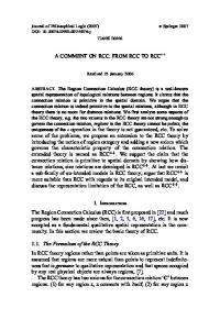
Figure 1: Ground floor plan
2
Design of RCC structure
Floor level plan:
Figure 2: floor level plan
3
Design of RCC structure
2. LOADING 2.1 Introduction Structural loads or actions are forces, deformations, or accelerations applied to a structure or its components. Loads cause stresses, deformations, and displacements in structures. Assessment of their effects is carried out by the methods of structural analysis. Excess load or overloading may cause structural failure, and hence such possibility should be either considered in the design or strictly controlled. A structure goes under different types of loading in reality, so while designing we have to consider all the loads. 2.2 Types of load The following loads we have considered in our design: Dead load Live load Seismic load Wind load 2.3 Dead Load The dead of the structure is static load on it. The static load is a load which does not changes with time. In our structure the dead load is the self-weight of the structure, load of floor finish and load of infill walls. The values of the dead load are taken from IS 875 (part 1): 1987 Unit weight of concrete= 25 kN/m3 Unit weight of floor finish 1 kN/m2 Unit weight of infill wall (brick wall) 18.85 kN/m3 Unit weight of 3.5 feet infill wall 11.9 kN/m
4
Design of RCC structure
2.4 Live Load Live loads are the dynamic load on a structure that changes with time, in our structure the live load values are taken from IS 875 part 2:1987. The values are taken from Table 1 of IS 875 part 2:1987. The value of live load is taken as 3 kN/m2 on slab or floor level. The value of live load on roof is taken zero. The value of live load on beams has come from load transfer of floor. The value of live load on column has come from load transfer of beam. The value of live load on foundation has come from load transfer of column. 2.5 Seismic Load Seismic load is also the dynamic load that changes its direction and magnitude with respect to time. The value of seismic load has been calculated from IS 1893:2002. The different coefficients are adopted for calculation are: Type of structure: RC Moment resisting frame. Height of structure 17.5m Type of soil: hard soil Earthquake zone: zone 5 Importance factor 1 2.6 Wind Load Wind is also the dynamic load that changes its direction and magnitude with respect to time. The wind load is calculated as per IS 875 part 3:1987. The different coefficients adopted are: Terrain category 3
5
Design of RCC structure
Height of building 17.5m Class of structure: class A Basic wind speed Vb: 39m/s K1=1 (probability factor or risk coefficient clause 5.3.1) K2 (terrain height and structure size factor clause 5.3.2) K3=1 (topography factor clause 5.3.3) Vz (Design wind speed) = Vb * K1 * K2* K3 Design wind pressure= Pz= .6Vz2
Design wind pressure at different heights Height(m)
K2
Vz (m/s)
Pz (N/m2)
10
.91
35.49
755.74
11
.922
35.958
775.79
12
.934
36.426
796.11
13
.946
36.894
816.70
14
.958
37.362
836.55
15
.97
37.83
858.67
16
.978
38.142
872.89
17
.986
38.454
887.23
17.5
.99
38.61
894.44
Table no 2.1 Note: During load combinations one out of earthquake load and wind load is taken at a time.
6
Design of RCC structure
2.7 Load on Slab On floor level Live load = 3kN/m2 Thickness of slab= 150 mm Dead load = thickness * density of concrete = 3.75 kN/m2 Floor finish = 1 kN/m2 Factored Total load on slab = 1.5(3+1+3.75) = 11.625 kN/m2 On Roof level Live load = 0kN/m2 Thickness of slab= 150 mm Dead load = thickness * density of concrete = 3.75 kN/m2 Floor finish = 1 kN/m2 Factored Total load on slab = 1.5(0+1+3.75) = 7.125 kN/m2 2.8 Loads on beam The live load on beam comes from load distribution of slab load and dead load is a self-weight of beam. Beams goes under flexural loading Load on beam
Dead load: load from infill wall+ self-weight
7
Design of RCC structure
Load on beam at roof level BEAM NO. B1 B2 B3 B4 B5 B6 B7 B8 B9 B10 B11 B12 B13 B14 B15 B16 B17 B18 B19 B20 B21 B22 B23 B24 B25 B26 B27 B28 B29
L (m) 3.2766 3.63855 2.00025 2.057 3.5814 3.2766 3.5814 3.8862 1.4478 3.5814 3.8862 3.8862 1.4478 3.5814 0.9144 3.5814 3.5814 3.8862 0.9144 3.5814 3.5814 3.8862 4.1148 2.667 3.2766 4.1148 2.667 3.2766 1.905
Live load1(KN/m) 5.84 6.787 6.787 6.787 13.12 11.673 11.89 11.8 0 5.56 10.15 3.264 0 9.99 0 6.39 6.33 6.75 5.16 11.55 13.67 10.49 5.16 11.78 13.18 0 4.76 5.84 0 Table 2.2
Dead load2(KN/m) 11.9 11.9 11.9 11.9 11.9 11.9 11.9 11.9 11.9 11.9 11.9 11.9 11.9 11.9 11.9 11.9 11.9 11.9 11.9 11.9 11.9 11.9 11.9 11.9 11.9 11.9 11.9 11.9 11.9
TOTAL LOAD(KN/m) 17.74 18.69 18.69 18.69 25.023 23.573 23.79 23.7 11.9 17.46 22.05 15.164 11.9 21.89 11.9 15.59 18.23 18.65 17.06 23.45 25.57 23.39 17.06 23.68 25.08 11.9 16.66 17.74 11.9
8
Design of RCC structure
Load on beam at floor level BEAM L (m) NO.
live load(KN/m)
Dead load(KN/m)
TOTAL LOAD(KN/m)
B1
3.2766
9.52
23.44
32.96
B2
3.63855
11.08
11.9
22.98
B3
2.00025
11.08
23.44
34.52
B4
2.057
11.08
23.44
34.52
B5
3.5814
21.41
23.44
44.85
B6
3.2766
19.05
23.44
42.84
B7
3.5814
19.4
23.44
42.84
B8
3.8862
19.26
23.44
42.7
B9
1.4478
0
23.44
23.44
B10
3.5814
8.97
23.44
32.41
B11
3.8862
16.55
23.44
39.99
B12
3.8862
5.33
11.9
17.23
B13
1.4478
0
11.9
11.9
B14
3.5814
19.97
11.9
31.87
B15
0.9144
0
23.44
23.44
B16
3.5814
10.42
23.44
33.86
B17
3.5814
10.53
23.44
33.77
B18
3.8862
11.02
23.44
34.46
B19
0.9144
8.42
23.44
31.86
B20
3.5814
18.84
23.44
42.28
B21
3.5814
22.31
23.44
45.75
9
Design of RCC structure
B22
3.8862
17.12
23.44
40.56
B23
4.1148
8.42
23.44
31.86
B24
2.667
19.23
23.44
42.67
B25
3.2766
21.5
23.44
44.94
B26
4.1148
0
11.9
11.9
B27
2.667
7.76
23.44
24.2
B28
3.2766
9.52
23.44
32.96
B29
1.905
0
23.44
23.44
Table 2.3
10
Design of RCC structure
Figure 3 : loading on beam from floor distribution
11
Design of RCC structure
2.9 Load on column The load on column comes from the adjoining beams. The half of the load on a beam transfer to the column, this load acts as live load on the column. The dead load on the column is its self weight. The live load on the column is reduced going down to the floor as per floor load reduction given in IS 875 part 2:1987 clause 3.2.1 FLOOR LOAD AT COLUMN COLUMN FLOOR LOAD ON COLUMN FLOOR LOAD ON COLUMN NO AT LOWER LEVEL (kN) AT TOP LEVEL (kN) C1
33.71
14.22
C2
48.25
25.94
C3
28.75
18.7
C4
28.98
15.3
C5
79.54
43.73
C6
50.63
27.32
C7
55.54
30.24
C8
87.44
49.06
C9
65.23
36.28
C10
50
29.1
C11
55.22
28.77
C12
65.98
35.48
C13
53.49
29.1
C14
34.27
23.01
C15
48.65
24.78
12
Design of RCC structure
C16
57.07
31.29
C17
20.34
13.53
C18
30.5
22.06
C19
37.82
25.43
C20
21.89
16.9
TABLE 2.4 Dead load on column is the self-weight of column it is calculated as under .4*.4*3.5*25=14kN Factored dead load= 1.5*14=21kN. The maximum load is on column no. 8 so we have calculate all the load on column 8. Loading on column no. 8 FLOOR NO. FROM TOP
FLOOR LOAD
DESIGN LIVE LOAD
1
49.06
49.06
2
87.44
(49.06 +87.44)*(1-0.1) 42 =122.85
164.85
3
87.44
(49.06 +87.44*2)*(1-0.2) 63 =179.152
242.152
4
87.44
(49.06 +87.44*3)*(1-0.3) 84 =217.966
301.966
5
87.44
(49.06 +87.44*4)*(1-0.4) 105 =239.292
344.292
(kN)
(kN)
DEAD LOAD (kN)
TOTAL DESIGN LOAD (kN)
21
70.06
Table 2.5
13
Design of RCC structure
Column position
Figure 4: column positions
14
Design of RCC structure
2.10 Load on Footing Footing is a structure that transmits the load coming from super structure to o Live load for footing will be taken from the load of column 8 at base level which is the maximum. Dead load for the footing is to be taken as 10% of live load. 2.11 Load on Stair-case Staircase is used to travel the vertical distance through number of steps. It connects one floor level to another floor level. Live load for the staircase will be taken as 3kN/m2. (For non-overcrowding) Dead load for staircase will be calculated in chapter stair case itself due to not having any codal provision about it.
15
Design of RCC structure
3. Analysis and design using STAAD.PRO 3.1
Introduction to STAAD.PRO As it is named Structure analysis and design program. It is used to analyze the any frame structure and design the different type of structural elements. It is programmed to design as per the finite element method and it does analysis on the basis of stiffness matrix system.
3.2
Modelling on STAAD.PRO To analyze the structure we have make it first. To create structure the basic step is to create the nodes and then add beams on it. We have done the modelling and our structure looks like this:
Figure 5: Modeling on STAAD.PRO 3.3 Specification and loading pattern on structure We have provided the fixed supports.
16
Design of RCC structure
Beam size 300*350mm Column size 400*400mm Loading When we consider seismic load we have define it first else it will show error in analysis. After that we have to define wind load too. Dead load will be the self-weight of the structure. Live load will be given as floor load. The images below will show how these definitions and loading has provided in the structure.
Figure 6: Earthquake definition
17
Design of RCC structure
Figure 7: Wind load definition
Figure 8: Floor load (2 way)
18
Design of RCC structure
Since the floor load distribution varies from slab to slab depending upon its length, so we will change the range as per slab.
Figure 9: Floor load (one way) The dead load of the structure is the self-weight of structure is directly assigned using the factor -1. After applying loads we have make combinations for our structure to find the critical combination for our structure. The load combinations are like that:
Figure 10: load combinations
19
Design of RCC structure
Define once for earthquake and then for wind load. Using M20 concrete and Fe415 steel we have designed our beams and columns. Result As we have analyzed and designed our structure in STAAD.PRO we have got a file for it. The basic analysis results tell that beam no 156 is in maximum stress and critical load combination for our structure is 1.5(DEAD LOAD+LIVE LOAD).
Table 3.1: Result summary from STAAD.PRO
20
Design of RCC structure
Figure 11: Stresses on beam no 1561
21
Design of RCC structure
Figure 12: loading diagram
Figure 13: Bending diagram *The above result are not complete. For complete results look for Appendix 2, where we have attached some important results of STAAD.PRO file.
22
Design of RCC structure
4. Slab 4.1) Introduction A concrete slab is a common structural element of modern buildings. Horizontal slabs of steel reinforced concrete, typically between 100 and 500 millimeters thick, are most often used to construct floors and ceilings, while thinner slabs are also used for exterior paving. Types
One way slab Two way slab
In one way slab load distribution is along the longer span. i.e load transfers to longer beam there is no load transfer on beams of small span. Two way slab in which load transfers in all beams that supports it. Difference between one way and two way slab One Way Slab
Two Way Slab
One way slab is supported by beams in Two way slab is supported by beams in only 2 sides. all four sides.
The ratio of longer span panel (L) to The ratio of longer span panel (L) to shorter span panel (B) is equal or greater shorter span panel (B) is less than 2. than 2. Thus, L/B >= 2 Thus, L/B < 2.
Main reinforcement is provided in only Main reinforcement is provided in both one direction for one way slabs. the direction for two way slabs. Table 4.1: Difference between one way and two way slab
23
Design of RCC structure
Load distribution One way slab
Figure 14: one way slab load distribution Two way slab
Figure 15: two way slab load distribution
24
Design of RCC structure
4.2) Design As per the plan we have 5 two way slab and 4 one way slab. Plan of slab
Figure 16: plan of slab
4.3) Design of One way slab W=11.625 kN/m for floor and 7.125 kN/m for top M=Wl2/8
25
Design of RCC structure
Shear force= wl/2
S4
S5
S6
S9
Ly
3.8862
5.6388
5.5626
4.4958
Lx
.9144
1.905
2.0574
1.4478
Lx/Ly=r
4.25
2.96
2.7
3.1
M for 1.215 floor(kN-m)
5.27
6.14
3.046
M for top(kN- .744 m)
3.23
3.77
1.87
Vu floor(kN)
5.32
11.07
11.96
8.42
Vu top(kN)
3.256
6.78
7.33
5.16
Table 4.2: one way slab specifications S6 has the maximum moment and shear, we will go for design of that slab first. Mmax=6.14kN/m at floor level Vmax =11.96kN Fy=415Mpa; FCK=20Mpa Effective depth = 150-20-4=126mm 150 slab thickness 20mm cover and will use 8 mm dia bars 2
Depth required=√
𝑀𝑢 𝑅𝑢×𝐵
Ru=2.76 and B=1000 Mu=Mmax D comes out 47.166 .12% (IS 456:2000 clause 40.2.1.1 table 19)
𝜏c=.296 N/mm2 For 150 mm thick slab K=1.3 𝜏c=1.3*.296=.384 N/mm2 .384>.095 it is okay No shear reinforcement is required Check for deflection: Pt=.17% Fs= .58 fy
𝐴𝑠𝑡 𝑟𝑒𝑞𝑢𝑖𝑟𝑒𝑑 𝐴𝑠𝑡 𝑝𝑟𝑜𝑣𝑖𝑑𝑒𝑑
=172.3 N/mm2 Kt=2(clause 23.2.2.1) figure 4 Is 456:2000 𝐿 𝐷
(𝑝𝑟𝑜𝑣𝑖𝑑𝑒𝑑) = 20𝑘t
25.9 & 40 𝐿 𝐷
𝐿
(𝑝𝑟𝑜𝑣𝑖𝑑𝑒𝑑) < (𝑚𝑎𝑥) hence okay 𝐷
Check for development length M.O.R at support by 8mm dia bars @ 200mm c/c spacing=M1 Ast’=Ast/2 = 125.75 mm M1= .87 fy Ast’*d(1-
𝐴𝑠𝑡 ′ 𝐹𝑦
𝐹𝑐𝑘∗𝐵∗𝑑
)
28
Design of RCC structure
= 5.602 kN-m Vu=11.96 KN Provide no hooks Lo=0 𝑀1 𝑉
+ 𝐿o=468.39mm
Ld = 47(DIA of bar)= 47*8=376mm 𝑀1 𝑉
+ 𝐿o > Ld
Hence okay Since as the results came out we have to provide minimum reinforcement i.e .12%bd for the maximum moment. As the depth is same for all the slab and moment is less we will provide the same reinforcement for all slabs for floor as well as roof level.
Detailing of one way slab is given below
Figure 17: Detailing of one way slab 4.4) Design of two way slab W=11.625kN/m2 Case: long edge discontinuous table 26 IS 456:2000 Mux = 𝛼 xwlx2
29
Design of RCC structure
Muy = 𝛼 ywly2 V= wlx (
𝑟 2+𝑟
)
r = Ly/Lx
S1
S2
S3
S7
S8
Ly(m)
3.8862
3.5814
3.8862
3.5814
3.5814
Lx(m)
3.2766
3.2766
3.5814
3.2766
2.667
Ly/Lx
1.2
1.1
1.1
1.1
1.3
𝛼 x +ive
.039
.033
.033
.033
.044
𝛼 x –ive
.052
.044
.044
.044
.057
𝛼 y +ive
.028
.028
.028
.028
.028
𝛼 y –ive
.037
.037
.037
.037
.037
Mux +ive(KN- 4.867 M)
4.11
4.92
4.11
3.638
Muy +ive(KN- 3.494 M)
3.494
4.175
3.4941
2.315
Mux -ive(KN- 6.489 M)
5.4915
6.56
5.491
4.713
Muy –ive(KN- 4.616 M)
4.616
5.515
4.616
3.058
Vu(KN)
13.51
14.77
13.51
12.212
14.28
Table 4.3: specifications of two way slab Since S3 slab has the maximum moment and shear value so we will go for the design of S3 slab of floor B=1000mm d=150mm Mux=6.56 kN-m Muy=5.515 kN-m V= 14.77KN
30
Design of RCC structure
𝑀𝑢
2
Depth required=√
𝑅𝑢×𝐵
Ru=2.76 and B=1000 =48.75mm D req < D assumed hence okay Design of Main reinforcement: Along shorter span: Middle strip= ¾ ly =2.91m dx(effective depth)= 150-20-4=126mm 150 slab thickness 20mm cover and will use 8 mm dia bars Mux=.87*fy*Ast*d{1-
𝐴𝑠𝑡∗𝐹𝑦
𝐹𝑐𝑘∗𝑏∗𝑑
}
Putting values Astx = 147.8 mm2 Ast min= .12%bd = 180mm2 Provide 8mm dia bars Area of 1 bar= 50.3mm2 Spacing=
1000×𝐴𝑟𝑒𝑎 𝑜𝑓 1 𝑏𝑎𝑟
𝐴𝑟𝑒𝑎 𝑜𝑓 𝑠𝑡𝑒𝑒𝑙 𝑖𝑛 𝑡𝑒𝑛𝑠𝑖𝑜𝑛
=279.44mm Provide 200 mm spacing Actual Ast =
1000×𝐴𝑟𝑒𝑎 𝑜𝑓 1 𝑏𝑎𝑟 𝑆𝑝𝑎𝑐𝑖𝑛𝑔
= 251.5 mm2
Provide 8mm bars @200 mm c/c spacing in the middle strip of width =2.915m Along longer span
31
Design of RCC structure
Width of middle strip=3/4lx=2.69m Dy= 150-20-8-4=118mm Muy=.87*fy*Ast*d{1-
𝐴𝑠𝑡∗𝐹𝑦
𝐹𝑐𝑘∗𝑏∗𝑑
}
Putting all the values solving quadratic Asty= 132.54mm2 AstY min= .12%bd=180mm2 Provide 8mm dia bars Area of 1 bar= 50.3mm2 Spacing=
1000×𝐴𝑟𝑒𝑎 𝑜𝑓 1 𝑏𝑎𝑟
𝐴𝑟𝑒𝑎 𝑜𝑓 𝑠𝑡𝑒𝑒𝑙 𝑖𝑛 𝑡𝑒𝑛𝑠𝑖𝑜𝑛
=279.44mm Provide 250 mm spacing Actual Ast =
1000×𝐴𝑟𝑒𝑎 𝑜𝑓 1 𝑏𝑎𝑟 𝑆𝑝𝑎𝑐𝑖𝑛𝑔
= 201.2 mm2
Provide 8mm bars @200 mm c/c spacing in the middle strip of width =2.69m Edge strip: Reinforcement Along shorter span=.49m Along longer span=.45m Ast min= .12%bd=180mm2 Spacing=
1000×𝐴𝑟𝑒𝑎 𝑜𝑓 1 𝑏𝑎𝑟
𝐴𝑟𝑒𝑎 𝑜𝑓 𝑠𝑡𝑒𝑒𝑙 𝑖𝑛 𝑡𝑒𝑛𝑠𝑖𝑜𝑛
=279.44mm Provide 250mm c/c spacing Actual Ast =
1000×𝐴𝑟𝑒𝑎 𝑜𝑓 1 𝑏𝑎𝑟 𝑆𝑝𝑎𝑐𝑖𝑛𝑔
= 201.2 mm2
Note:
32
Design of RCC structure
*width of middle strip = ¾ lx or ly = wm Along the larger and shorter span respectively *width of edge strip= ½(lx-Wm ) Check for shear: 𝜏𝑣 = =
𝑉𝑢 𝑏𝑑
= nominal shear stress
14.28×1000 150×1000
=.095 N/mm2
Pt =
100×𝐴𝑠𝑡 100×251.5 𝑏𝑑
=
150×1000
= .17%>.12% (IS 456:2000 clause 40.2.1.1 table 19)
𝜏c=.296 N/mm2 For 150 mm thick slab K=1.3 𝜏c=1.3*.296=.384 N/mm2 .384>.095 it is okay No shear reinforcement is required Check for deflection: Pt=.17% Fs= .58 fy
𝐴𝑠𝑡 𝑟𝑒𝑞𝑢𝑖𝑟𝑒𝑑 𝐴𝑠𝑡 𝑝𝑟𝑜𝑣𝑖𝑑𝑒𝑑
=172.3 N/mm2 Kt=2(clause 23.2.2.1) figure 4 Is 456:2000 𝐿 𝐷
(𝑝𝑟𝑜𝑣𝑖𝑑𝑒𝑑) = 20𝑘t
25.9 & 40
33
Design of RCC structure 𝐿
𝐿
𝐷
(𝑝𝑟𝑜𝑣𝑖𝑑𝑒𝑑) < (𝑚𝑎𝑥) hence okay 𝐷
Torsional reinforcement: Mesh size= lX/5=.716m Provide mesh size of 720mm *720mm Area of torsional reinforcement = 3/4 Astx =188.625mm Providing 8 mm bars Area of 1 bar= 50.3mm2 Spacing=
1000×𝐴𝑟𝑒𝑎 𝑜𝑓 1 𝑏𝑎𝑟
𝐴𝑟𝑒𝑎 𝑜𝑓 𝑠𝑡𝑒𝑒𝑙 𝑖𝑛 𝑡𝑒𝑛𝑠𝑖𝑜𝑛
=266.67mm Provide 250mm c/c spacing Actual Ast =
1000×𝐴𝑟𝑒𝑎 𝑜𝑓 1 𝑏𝑎𝑟 𝑆𝑝𝑎𝑐𝑖𝑛𝑔
= 201.2 mm2
Note: Arrangement of reinforcement Bending half of the main bars at a distance of .15lx=.5m from the center of supporting beam along x direction at top. Available length of bars at top = 500-130=370mm from the center of support in x direction Similarly in y direction .15Ly=.58m Available length of bars at top=580-130=450mm Since as the results came out we have to provide minimum reinforcement i.e .12%bd for the maximum moment. As the depth is same for all the slab and moment is less we will provide the same reinforcement for all slabs for floor as well as roof level. Detailing of two way slab is given below:
34
Design of RCC structure
Figure 18: Plan of bottom reinforcement
35
Design of RCC structure
Figure 19: plan of top reinforcement
36
Design of RCC structure
Figure 20: section along longer span
Figure 21: section along shorter span
37
Design of RCC structure
5. Beam 5.1 Introduction A beam is a structural element that is capable of withstanding load primarily by resisting bending. The bending force induced into the material of the beam as a result of the external loads, own weight, span and external reactions to these loads is called a bending moment. It is also called as flexural member of the structure as it has to resist the flexural or bending load. 5.2 Design of beam Design constants For Fe 415steel, 𝑓𝑦 = 415𝑁/𝑚𝑚2 For M20 concrete, 𝑓𝑐𝑘 = 20𝑁/𝑚𝑚2 𝑥𝑢,𝑚𝑎𝑥 𝑑
= 0.48 L =3.8862m Width of web = bw = 300mm
D =350mm d = 350-20-8-16/2 [20mm nominal cover, 8mm# stirrups, and 16mm # main bars] Depth of flange = Df = 150mm
(equals to depth of slab)
l0 =0.7L =0.7*3.8862m =2.72m Width of flange will be given by equation 𝑏𝑓 =
𝑙0 6
+ 𝑏𝑤 + 6𝐷𝑓
∴ 𝑏𝑓 =
2720 6
[Clause 23.1.2 IS456: 2000]
+ 300 +6*150
= 1653.33 ≈ 1650𝑚𝑚
38
Design of RCC structure
Design forces The bending moment and shear force coming on different beams ar as follows BEAM NO.
L (m)
TOTAL LOAD(kN/m)
BENDING MOMENT(kN/m2)
SHEAR FORCE (kN)
B1
3.2766
32.96
44.23
53.99
B2
3.63855
22.98
38.03
41.81
B3
2.00025
34.52
17.26
34.52
B4
2.057
34.52
18.26
35.5
B5
3.5814
44.85
71.91
80.31
B6
3.2766
42.84
57.02
69.61
B7
3.5814
42.84
68.69
76.71
B8
3.8862
42.7
80.61
82.97
B9
1.4478
23.44
6.14
16.96
B10
3.5814
32.41
51.96
58.04
B11
3.8862
39.99
71.49
77.7
B12
3.8862
17.23
32.53
33.48
B13
1.4478
11.9
3.12
8.62
B14
3.5814
31.87
45.39
50.69
B15
0.9144
23.44
2.45
10.72
B16
3.5814
33.86
54.29
60.63
B17
3.5814
33.77
54.15
60.47
B18
3.8862
34.46
65.05
66.96
B19
0.9144
31.86
3.33
14.57
B20
3.5814
42.28
67.79
75.71
B21
3.5814
45.75
73.35
81.92
B22
3.8862
40.56
76.57
78.81
39
Design of RCC structure
B23
4.1148
31.86
67.43
65.55
B24
2.667
42.67
37.94
56.9
B25
3.2766
44.94
60.21
73.63
B26
4.1148
11.9
25.19
24.48
B27
2.667
24.2
21.52
32.27
B28
3.2766
32.96
44.23
53.99
B29
1.905
23.44
10.63
22.33
Table 5.1: forces in beam As we are designing the beam for maximum forces, the maximum bending moment is on Beam no. 8. ∴ Bending moment will be Mu =80.61kN-m And Shear force will be Vu =82.97 kN Mu,lim. =0.138𝑓𝑐𝑘 𝑏𝑤 𝑑 2 = 0.138*20*300*3142 As Mu,lim. is greater than Mu hence singly reinforced beam has to be designed. Design of longitudinal reinforcement Assume xu =Df Mu1 =0.36fck bf Df (d-0.42Df) = 0.36*20*1650*150(314-0.42*150) =447.28 kN-m > Mu ∴ xu < Df Hence neutral axis lies in the flange part Now, Ast is given by equation
40
Design of RCC structure 0.5𝑓𝑐𝑘
Ast =
=
𝑓𝑦
0.5∗20 415
4.6𝑀𝑢
[1 − √1 − 𝑓
𝑐𝑘 𝑏𝑓 𝑑
2
] 𝑏𝑓 𝑑
4.6∗80.6∗106
[1 − √1 − 20∗1650∗3142] 1650 ∗ 314
=732.90mm2 Provide 16mm # bars 𝜋
∴ A# = 162 4
=201.06mm2 No. of bars required = =
𝐴𝑠𝑡 𝐴# 732.9
201.06
=3.645 ≈ 4 𝑏𝑎𝑟𝑠
Requirements for Ductile Detailing as per IS 13920:1993 1) The top reinforcement should contain at least two bars throughout the section. [clause 6.2.1 (a) IS 13920:1993] Therefore, provide 2 bars of 12mm# in compression at cover of 50mm from top. 2) The positive steel at a joint face must be at least equal to half the negative steel at that face. [ clause 6.2.3 IS 13920:1993] Therefore provide 2 bars of 16mm # in the compression at the ends of beam. Shear reinforcement Shear reinforcement is designed to resist the shear forces coming on the structure. This is designed taking in account the shear forces. We have , wu =42.7 kN Vu = 82.97 kN
41
Design of RCC structure
The critical section lies at a distance d =314mm from the face of the support or 314+ 200 =514mm from the centre of support(column). ∴
VuD = 82.97- 42.7*0.514 = 61.02 kN
And 𝜏𝑣 =
𝑉𝑢𝐷 𝑏𝑤 𝑑
=
61020 300∗314
Also pt = 100
𝐴𝑠𝑡 𝑏𝑑
=0.65N/mm2
=0.78%
For 0.78% Ast and M20 concrete , we get 𝜏𝑐 =0.567 N/mm2 [Table 19, IS 456:2000] Vuc = 𝜏𝑐 𝑏𝑑 = 0.567*300*314 =53.41kN 𝜏𝑣,𝑚𝑎𝑥 = 2.8𝑁/𝑚𝑚2 Since 𝜏𝑣 < 𝜏𝑣,𝑚𝑎𝑥 it is OK However, 𝜏𝑣 > 𝜏𝑐 , hence shear reinforcement is necessary. Vus =VuD –Vuc = 61.02 – 53.41 = 7.61kN The shear resistance of nominal stirrups is given by Vus,min =0.4bd =0.4*300*314 = 37680N = 37.68kN Now Spacing of stirrups is given by, sv =
0.87𝑓𝑦 𝐴𝑠𝑣 𝑑 𝑉𝑢𝑠,𝑚𝑖𝑛
Providing two legged stirrupsof 8mm dia. Bars , Asv =50.3mm2 ∴
𝑠𝑣 =
0.87∗415∗50.3∗314 37680
=151.34mm
Provide 150mm # c/c spacing of two legged stirrups throughout the section.
42
Design of RCC structure
5.3 Detailing of beam
Figure 22: longitudinal cross section of beam
Figure 23: longitudinal reinforcement at mid span
43
Design of RCC structure
Figure 24: longitudinal reinforcement at support
44
Design of RCC structure
6. Column
6.1 Introduction Column is a vertical compression member supporting floors and girders in a building. Columns are subjected to heavy loads and transfers loads from floor to footing. These are also used to supports beams, generally made up of reinforced concrete. Column positions are already mentioned in chapter 2. And column load has also mentioned in chapter 2. From the data we have design column no. 8 6.2 Design of column(bottom level) Size of column: 400 mm * 400 mm Pu= 345kN; D=b=400mm L=3.5m Fck=20N/mm2 Fy=415N/mm2 Lex=ley=.85l=.85(3500) =2975mm 𝐿𝑒𝑥 = 7.4375 < 12 𝑏 Hence the column is short Let us take an effective cover = 60mm Step 1: check for minimum eccentricities: Eymin=exmin=
𝐿𝑥 500
+
𝐷 30
=
3500 500
+
600 30
= 20.33𝑚𝑚 > 20𝑚𝑚
Mux=Muy=Puexmin=345*20.33=7.013 kN-m Selection of trail reinforcement: Taking a=1.15
45
Design of RCC structure
Mu=α√𝑀𝑢𝑥 2 + 𝑀𝑢𝑦^2 =11.4kN-m Mu=11.4 kN-m design for this moment as maximum in any direction. From chart 44 of limit state design of RCC structure B.C.Punmia 𝑑′ 𝐷
=
600 400
= .15 hence chart 44 has been used 𝑃𝑢 345 ∗ 103 = = .11 𝑓𝑐𝑘 𝑏𝐷 20 ∗ 400 ∗ 400 𝑀𝑢 11.4 ∗ 106 = = .0089 𝑓𝑐𝑘 ∗ 𝑏𝑑 2 20 ∗ 400 ∗ 4002
𝑃
= .02 (From chart 44 of limit state design for RCC b.c.punmia)
𝑓𝑐𝑘
P=.02*20=.4% Hence we take min value of p=.8% P=
100𝐴𝑠𝑡 𝑏𝐷 𝐴𝑠𝑡100
.8=
𝑏𝐷
= 1280mm2
Provide 16mm dia bars Area of 1 bar= 𝜋 No. of bars=
𝑑2 4
=200.96mm2
𝐴𝑠𝑡
𝑎𝑟𝑒𝑎 𝑜𝑓 1 𝑏𝑎𝑟
=
1280 200.96
= 6.3 ≈ 8
Provide 8 bars of 6mm dia Actual AST =
8×𝜋×𝑑 2 4
= 1607.68mm2
P=100Ast / bD =1%
46
Design of RCC structure
𝑃 1 = = .05 𝑓𝑐𝑘 20 Uniaxial moment capacity of the above section: 𝑑′ = .15 𝐷 𝑃𝑢 345 ∗ 103 = = .11 𝐹𝑐𝑘 ∗ 𝑏 ∗ 𝐷 20 ∗ 400 ∗ 400 𝑃 1 = = .05 𝑓𝑐𝑘 20 𝑀𝑢 𝑓𝑐𝑘∗𝑏∗𝐷2
= .09( from chart 44)
Mu = .09*20*400*400^2 = 115kN Computation of PUZ P=1, fy=415N/mm2 , fck=20N/mm2 𝑃𝑢𝑧 𝐴𝑔
= 12𝑁/𝑚𝑚2 (from chart 63 of limit state design for RCC b.c.punmia)
Puz=12*400*400=1920 kN 𝑃𝑢 345 = = .20 𝑃𝑢𝑧 1920 𝑀𝑢𝑥 𝑀𝑢𝑦 7.013 = = = .06 𝑀𝑢𝑥1 𝑀𝑢𝑦1 115 From chart 64 of of limit state design for RCC b.c.punmia The above values are greater than the actual value of 0.05. Hence ok. Design of transverse reinforcement: Diameter of lateral ties ≥
𝑑𝑖𝑎 𝑜𝑓 𝑏𝑎𝑟𝑠 4
≥
16 4
47
Design of RCC structure
Provide 6mm dia ties Pitch: b=400; 16(dia of bar) = 256; 300 whichever is less. Hence provide 6mm lateral ties @256mm c/c. 6.3 Design of column (top-level) Size of column: 400 mm * 400 mm Pu=71kN; D=b=400mm L=3.5m Fck=20N/mm2 Fy=415N/mm2 Lex=ley=.85l=.85(3500) =2975mm 𝐿𝑒𝑥 = 7.4375 < 12 𝑏 Hence the column is short Let us take an effective cover = 60mm Step 1: check for minimum eccentricities: Eymin=exmin=
𝐿𝑥 500
+
𝐷 30
=
3500 500
+
600 30
= 20.33𝑚𝑚 > 20𝑚𝑚
Mux=Muy=Puexmin=71*20.33=1.4 kN-m Selection of trail reinforcement: Taking a=1.15 Mu=α√𝑀𝑢𝑥 2 + 𝑀𝑢𝑦^2 =2.3kN-m Mu=2.3 kN-m design for this moment as maximum in any direction. From chart 44 of limit state design of RCC structure B.C.Punmia
48
Design of RCC structure 𝑑′ 𝐷
=
600 400
= .15 hence chart 44 has been used 𝑃𝑢 71 ∗ 103 = = .002 𝑓𝑐𝑘 𝑏𝐷 20 ∗ 400 ∗ 400 𝑀𝑢 2.3 ∗ 106 = = .002 𝑓𝑐𝑘 ∗ 𝑏𝑑 2 20 ∗ 400 ∗ 4002
𝑃
= .02 (From chart 44 of limit state design for RCC b.c.punmia)
𝑓𝑐𝑘
P=.02*20=.4% Hence we take min value of p=.8% P=
100𝐴𝑠𝑡 𝑏𝐷 𝐴𝑠𝑡100
.8=
𝑏𝐷
= 1280mm2
Provide 16mm dia bars Area of 1 bar= 𝜋 No. of bars=
𝑑2 4
=200.96mm2
𝐴𝑠𝑡
𝑎𝑟𝑒𝑎 𝑜𝑓 1 𝑏𝑎𝑟
=
1280 200.96
= 6.3 ≈ 8
Provide 8 bars of 6mm dia Actual AST =
8×𝜋×𝑑 2 4
= 1607.68mm2
P=100Ast / bD =1% 𝑃 1 = = .05 𝑓𝑐𝑘 20 Uniaxial moment capacity of the above section: 𝑑′ = .15 𝐷
49
Design of RCC structure
𝑃𝑢 71 ∗ 103 = = .02 𝐹𝑐𝑘 ∗ 𝑏 ∗ 𝐷 20 ∗ 400 ∗ 400 𝑃 1 = = .05 𝑓𝑐𝑘 20 𝑀𝑢 𝑓𝑐𝑘∗𝑏∗𝐷2
= .08( from chart 44)
Mu = .08*20*400*400^2 = 102kN Computation of PUZ P=1, fy=415N/mm2 , fck=20N/mm2 𝑃𝑢𝑧 𝐴𝑔
= 12𝑁/𝑚𝑚2 (from chart 63 of limit state design for RCC b.c.punmia)
Puz=12*400*400=1920 kN 𝑃𝑢 71 = = .02 𝑃𝑢𝑧 1920 𝑀𝑢𝑥 𝑀𝑢𝑦 1.4 = = = .013 𝑀𝑢𝑥1 𝑀𝑢𝑦1 102 From chart 64 of of limit state design for RCC b.c.punmia The above values are greater than the actual value of 0.05. Hence ok. Design of transverse reinforcement: Diameter of lateral ties ≥
𝑑𝑖𝑎 𝑜𝑓 𝑏𝑎𝑟𝑠 4
≥
16 4
Provide 6mm dia ties Pitch: b=400; 16(dia of bar) = 256; 300 whichever is less. Hence provide 6mm lateral ties @256mm c/c.
50
Design of RCC structure
6.4 Cross-section of column:
Figure 25: cross-section of column
51
Design of RCC structure
7. Foundation 7.1) Introduction A foundation is the lowest and supporting layer of structure. It transfers the dead load live load wind load and other loads to the surface of earth. Foundations are generally divided into two parts, shallow and deep foundations. Shallow foundations often called footings, are usually embedded about a metre or so into soil. In this section I will discuss about isolated concrete footing.
7.2) Design of Isolated footing
Design constant: For fe 415 and M20 combination we have 𝑋𝑢 𝑚𝑎𝑥 𝑑
= .479 And Ru=2.761
Size of column= 400*400mm b=400mm Vertical load= 345 kN Safe bearing capacity= 100 KN/m2 for soft soil Size of footing W=345KN Let W’ be equal to 10% of W= 35kN A=380/100=3.8m2 2
Size B of square √3.18=2m Provide a square footing of 2×2m Net upward pressure P0= 345/2*2=86.25 KN/m2
52
Design of RCC structure
Design of section: Depth on the basis of bending compression: Maximum bending moment acts at the face of column; and its magnitude 𝐵
M=P0 (𝐵 − 𝑏)2× 10⁶ N-mm 8
Mu=55.2*106 N-mm d= √
𝑀𝑢 𝑅𝑢∗𝐵
B=2000
d= 100mm D= 100+60=160mm (60mm cover)
Depth on the basis of one way shear: of the column, where shear force V is given 1
V=P0{ (𝐵 − 𝑏) − 𝑑} 2
=172.5(.8-d) 𝜏c=
𝑉𝑢 𝐵𝑑
=86.25(.8-d)/d K=1.27 (from clause 40.2.1.1 IS 456:2000) 𝜏c= .384 N/mm2 Permissible shear stress k𝜏c=1.27*.384=.488 N/mm2 .488= 86.25(.8-d)/d d=80mm
Depth for two way shear/check for two way shear: Take d greater of two d=100mm
53
Design of RCC structure
For two way shear (punching shear) the section lies at d/2 from the column face all round the width b0 of the section = b+d = 400+100=500mm Also, Factored Shear Force around the section is Fu = p0[B2-(b+d)2] = 86.25[22 – 0.502] = 323.44kN 𝜏v =
𝐹𝑢 4𝑏𝑜𝑑
=323.44*103 /(4*0.50*0.1) =1.617 N/mm
Permissible shear stress = ks 𝜏c Here ks =(0.5+βc) = (0.5 +1) =1.5 { βc = bx/by =400/400 =1) 𝜏c =0.25√𝑓𝑐𝑘 =0.25√20 =1.118N/mm2 Hence permissible shear stress = ks 𝜏c =1.5*1.118 =1.667N/mm2 Hence safe. Hence take d=100mm. using effective cover of 60mm total depth of footing will be D = 160mm. Provide total depth D = 200mm, therefore effective depth d will be 200-60= 140mm in one direction and 140-12 =128mm in other direction, with 12mm # in both the directions.
Design of steel reinforcement Since the actual depth d provided is more than that required for bending compression, we have an under-reinforced section. For this section Ast = =
0.5𝑓𝑐𝑘 𝑓𝑦 0.5∗20 415
4.6 𝑀𝑢
[1 − √1 − 𝑓𝑐𝑘 𝑏𝑑2] 𝑏𝑑 4.6∗55.2∗106
[1 − √1 − 20∗2000∗1402 ] 2000 ∗ 140
= 1199.17mm2 Using 12mm # bars , number of bars required will be equal to
54
Design of RCC structure 𝐴𝑠𝑡
No. of bars =
𝐴#
𝜋
A# = d2 = 113mm2 4
1199.17
Therefore no. of bars equals to =
113
= 10.6 ≈ 11 bars
Spacing of bars will be = width divided by no of bars =
2000 11
= 181.18mm ≈ 180mm Hence provide 11 bars of 12mm # at c/c spacing of 180mm in both the directions
Check for development length: Ld =47# =47*12 =564mm Providing 60mm side cover , development length of bars available will be 1
Ld(provided) = [𝐵 − 𝑏] − 60 2
1
= [2000 − 400] − 60 2
=740mm > Ld Hence safe.
Transfer of load at column base A2 =400*400 =160000mm2 A1 =[400 + 2(2*200)]2 =(1200)2 =1440000mm2 𝐴
1440000
∴ √ 1=√ =9 𝐴 160000 2
𝐴
Adopt maximum value of √ 1 =2 𝐴 2
55
Design of RCC structure
𝐴 Hence permissible bearing stress = 0.45𝑓𝑐𝑘 √ 1⁄𝐴 = 0.45*20*2 =18N/mm2 2 Actual bearing pressure =
345000 400∗400
=2.156N/mm2
Hence safe. Thus no separate dowel bars are required for the transfer of load.
7.3) Detailing of footing
Figure 26: plan of footing
56
Design of RCC structure
Figure 27: cross-section of footing
\
57
Design of RCC structure
8.STAIRCASE 8.1)INTRODUCTION A stairway, staircase, stairwell, flight of stairs, or simply stairs is a construction designed to bridge a large vertical distance by dividing it into smaller vertical distances, called steps. Stairs may be straight, round, or may consist of two or more straight pieces connected at angles. The step is composed of the tread and riser. Tread The horizontal distance between two consecutive risers. Riser The vertical portion between each tread on the stair. Special types of stairs include escalators and ladders. Some alternatives to stairs are lifts and inclined moving walkways as well as stationary inclined pavements. Staircase consists of flights and landing too. Flight: set of steps between floor and landing or landing to landing. A flight contains 9-12 steps at once and a landing must have to provide after that. Landing: it is a place from where direction of flight changes and it’s a place where we take rest from stepping upwards. 8.2)DESIGN of staircase As per the plan we have choose to design the dog logged stair case. Since the load of staircase carries by beam half load to upper beam and half load to lower beam, hence each of its floor takes the load of its own staircase. We have to design staircase for one floor only. Rest will be the same for each floor. Using M20 CONCRETE & Fe415 steel. fck=20N/mm2 & fy=415N/mm2
58
Design of RCC structure
Proportioning of various dimensions of staircase: Considering 2 flights of dog logged stair case. Floor height = 3.5m Height of one flight = 3.5/2m = 1.75m For residential building Riser height =175mm Tread length = 225mm No. of risers = 1.75/.175 =10 risers No. of tread = no. of riser -1=10-1 =9 Total horizontal distance of tread= 9*0.225= 2.025m Width of staircase 1m @ 10cm Width of landing = 1m Design of staircase Thickness of waist slab= l/20 (l= effective span) L= 4.025+2*(.230/2) = 4.255m Thickness of waist slab = 213mm Taking d=200mm and D=225mm Loading Weight of waist slab in plan (per m width of flight) = (D√1 +
𝑟∗𝑟 𝑡∗𝑡
) × 25𝑘𝑁/𝑚3
59
Design of RCC structure
√1 +
= .225
175^2 225^2
× 25
=7.126 kN/m
Weight of steps: 25𝑅𝑇 2𝑇 =
25×.175×.225 2×.225
= 2.1875 kN/m
Total dead load= 2.1875+7.126+1(floor finish) = 10.3135kN/m Live load= 3 kN/m (for not overcrowding) Total load= 3+10.3135= 13.3135kN/m Factored load= 1.5×13.3135=19.97kN/m
For landing Dead load: .225× 25 × 1 =
5.625𝑘𝑁 𝑚
Live load= 3kN/m Floor finish= 1kN/m Total factored load= 1.5(5.625+3+1) =14.4375 kN/m
Load diagram shall be as follows:
60
Design of RCC structure
Figure 28: loading on staircase Design moments: Reaction at supports Ra=Rb=
2×14.4375+2.025×19.97025 2
= 34.657 kN BM at mid span= 34.657 × 2.0125 − 14.4375 × 1.5125 −
19.9705×2.025 8
= 42.85546 kN-m Max. BM allowed or singly reinforced section with Fe415 bars MU lim = 0.1387fckbd2 = .138*20*1000*2002*10-6 = 110.4 kN-m Hence 110.4>42.8556 Section can be designed as singly reinforced.
Area of reinforcement: Mu= .87*fy * Ast * (1−
𝐴𝑠𝑡×𝑓𝑦 𝑏𝑑𝑓𝑐𝑘
)
fy =415; fck =20; d=200; b=1000; Ast=635.2 mm2
61
Design of RCC structure
Using 10mm bars Area of 1 bar =
𝜋×𝑑^2 4
= 78.53mm2 Spacing= 1000×
𝑎𝑟𝑒𝑎 𝑜𝑓 1 𝑏𝑎𝑟
= 1000×
𝐴𝑠𝑡 𝑟𝑒𝑞𝑢𝑖𝑟𝑒𝑑 78.53
= 123mm
635.2
Provide 10mm ∅ 𝑏𝑎𝑟𝑠 @ 100mm spacing Actual Ast = 1000×
𝐴𝑟𝑒𝑎 𝑜𝑓 1 𝑏𝑎𝑟 𝑠𝑝𝑎𝑐𝑖𝑛𝑔
= 1000 ×
78.53 100
= 785.3mm2
Distribution steel= .12% of area = .12% of (225×1000) = 270 mm2 Spacing = 1000×
78.53 270
= 290 mm
Provide 10mm ∅ 𝑏𝑎𝑟𝑠 @ 250mm spacing Actual Ast = 1000×
78.53 250
= 314.12 mm2
Development length Ld = 47∅= 47× 10= 470mm Provide 500mm length of bars Ld is required. *PLAN AND CROSS SECTIONAL VIEW AT MID SPAN IS SHOWN IN NEXT PAGE.
62
Design of RCC structure
8.3) Detailing of stair case
Figure 29: plan of staircase
63
Design of RCC structure
Figure 30: cross-section of staircase
64
Design of RCC structure
9.Shear wall 9.1) Introduction In structural engineering, a shear wall is a wall composed of braced panels (also known as shear panels) to counter the effects of lateral load acting on a structure. Wind and seismic loads are the most common loads braced wall lines are designed to counteract. In our structure we have shear wall to resist the dynamic load caused by lift. 9.2)Design of shear wall Design constants For Fe 415 fy = 415N/mm2 For M20 concrete fck = 20N/mm2 Horizontal length of wall =lw = 4m =4000mm Effective depth of wall = dw 0.8lw =0.8*4000 = 3200mm Thickness of wall = tw =150mm Vu = 245.464kN
[ Taken from STAAD. Pro EARTHQUAKE ANALYSIS ]
Design as per IS 13920:1993 General requirements 1. Minimum thickness of the wall should not be less than 150mm. In our structure thickness of shear wall is 150mm. Hence OK. [C 9.1.2] 2. The reinforcement has to be provided in two curtains in both the directions. [C 9.1.5] 3. Diameter of the reinforcement bar should be less than1/10th of the thickness of wall i.e., 1/10(150) =15mm. However we will use 8mm dia barsfor reinforcement. [C 9.1.6]
65
Design of RCC structure
Shear strength requirements The nominal shear stress, 𝜏𝑣 , shall be calculated as 𝜏𝑣 = 𝜏𝑣 =
𝑉𝑢 𝑡𝑤 𝑑𝑤 245464 150∗3200
= 0.51N/mm2
Assume horizontal and vertical reinforcement (As) as 0.25%and for M20 Permissible stress in concrte is 𝜏𝑐 = 0.36𝑁/mm2 [Table 19, IS 456:2000] Maximum shear stress= 𝜏𝑐,𝑚𝑎𝑥. =2.8N/mm2 [Table 20, IS 456:2000] Now 𝜏𝑐,𝑚𝑎𝑥 > 𝜏𝑣 > 𝜏𝑐 Hence shear reinforcement shall be provided. Now Vus = (𝜏𝑣 − 𝜏𝑐 ) twdw =(0.51-0.36)*150*3200 =72000N = 72kN Vus, min = 0.4 twdw =0.4*150*3200= 192000kN Spacing required for two legged 8mm# bars is Sv =
0.87 𝑓𝑦 𝐴# 𝑑𝑤 𝑉𝑢𝑠,𝑚𝑖𝑛
=
0.87∗415∗2∗50.3∗3200 192000
= 605.36mm
But maximum spacing is given by 1 lw/5 =4000/5 =800mm 2 3tw =3*150 =450mm 3 450mm Therefore provide Sv =450mm c/c This requires the ratio
𝐴# 𝑆𝑣
= 100.6/450 =0.22
Minimum horizontal reinforcement required is 0.0025 of gross area
66
Design of RCC structure
This requires ratio = 0.0025*150 =0.375 Therefore decrease the spacing, 𝐴# 𝑆𝑣
=0.375
Sv =100.6/0.375 =268.27mm c/c However provide 250mm c/c spacing. Flexural requirement As there are no boundary elements in shear wall in our structure , we have to provide at least 4 bars of minimum 12 mm diameter as per CLAUSE 9.3.3 IS 13920:1993 . Therefore provide vertical reinforcement of 4 bars of 12mm dia. arranged in two layers along the edges of the wall. 9.3) Detailing of shear wall
Figure 31: Reinforcement in shear wall
67
Design of RCC structure
CONCLUSION
Since we have designed our structure manually and as well as in STAAD.PRO, but we have designed only two structural elements in it i.e beams and columns only. We have found that our manual design is more economical than the design of STAAD.PRO.
68
Appendix 1
Design of RCC structure STAAD. Pro Output File for RCC Design
Sunday, April 27, 2014, 08:54 AM PAGE NO.
1
**************************************************** * * * STAAD.Pro * * Version 2007 Build 04 * * Proprietary Program of * * Research Engineers, Intl. * * Date= APR 27, 2014 * * Time= 8:52:38 * * * * USER ID: amazing arts * ****************************************************
1. STAAD SPACE INPUT FILE: cap3.STD 2. START JOB INFORMATION 3. ENGINEER DATE 11-FEB-14 4. END JOB INFORMATION 5. INPUT WIDTH 79 6. UNIT METER KN 7. JOINT COORDINATES 8. 1 0 0 0; 2 3.2766 0 0; 3 6.91515 0 0; 4 8.9154 0 0; 5 5.334 0 1.905 9. 6 8.9154 0 1.905; 7 0 0 3.8862; 8 3.2766 0 3.8862; 9 5.334 0 5.182 10. 10 8.9154 0 5.1816; 11 0 0 7.4676; 12 3.8862 0 7.4676; 13 5.334 0 7.8486 11. 14 8.9154 0 7.8486; 15 0 0 11.049; 16 3.8862 0 11.049; 17 0 0 11.9634 12. 20 8.9154 0 11.9634; 24 5.334 0 11.9634; 30 3.8862 0 11.9634; 31 0 3.5 0 13. 32 3.2766 3.5 0; 33 6.91515 3.5 0; 34 8.9154 3.5 0; 35 5.334 3.5 1.905 14. 36 8.9154 3.5 1.905; 37 0 3.5 3.8862; 38 3.2766 3.5 3.8862 15. 39 5.334 3.5 5.1816; 40 8.9154 3.5 5.1816; 41 0 3.5 7.4676 16. 42 3.8862 3.5 7.4676; 43 5.334 3.5 7.8486; 44 8.9154 3.5 7.8486 17. 45 0 3.5 11.049; 46 3.8862 3.5 11.049; 47 0 3.5 11.9634; 48 8.9154 3.5 11.9634 18. 49 5.334 3.5 11.9634; 50 3.8862 3.5 11.9634; 51 0 7 0; 52 3.2766 7 0 19. 53 6.91515 7 0; 54 8.9154 7 0; 55 5.334 7 1.905; 56 8.9154 7 1.905 20. 57 0 7 3.8862; 58 3.2766 7 3.8862; 59 5.334 7 5.1816; 60 8.9154 7 5.1816 21. 61 0 7 7.4676; 62 3.8862 7 7.4676; 63 5.334 7 7.8486; 64 8.9154 7 7.8486 22. 65 0 7 11.049; 66 3.8862 7 11.049; 67 0 7 11.9634; 68 8.9154 7 11.9634 23. 69 5.334 7 11.9634; 70 3.8862 7 11.9634; 71 0 10.5 0; 72 3.2766 10.5 0 24. 73 6.91515 10.5 0; 74 8.9154 10.5 0; 75 5.334 10.5 1.905; 76 8.9154 10.5 1.905 25. 77 0 10.5 3.8862; 78 3.2766 10.5 3.8862; 79 5.334 10.5 5.1816 26. 80 8.9154 10.5 5.1816; 81 0 10.5 7.4676; 82 3.8862 10.5 7.4676 27. 83 5.334 10.5 7.8486; 84 8.9154 10.5 7.8486; 85 0 10.5 11.049 28. 86 3.8862 10.5 11.049; 87 0 10.5 11.9634; 88 8.9154 10.5 11.9634 29. 89 5.334 10.5 11.9634; 90 3.8862 10.5 11.9634; 91 0 14 0; 92 3.2766 14 0 30. 93 6.91515 14 0; 94 8.9154 14 0; 95 5.334 14 1.905; 96 8.9154 14 1.905 31. 97 0 14 3.8862; 98 3.2766 14 3.8862; 99 5.334 14 5.1816; 100 8.9154 14 5.1816 32. 101 0 14 7.4676; 102 3.8862 14 7.4676; 103 5.334 14 7.8486 33. 104 8.9154 14 7.8486; 105 0 14 11.049; 106 3.8862 14 11.049; 107 0 14 11.9634 34. 108 8.9154 14 11.9634; 109 5.334 14 11.9634; 110 3.8862 14 11.9634 35. 111 0 17.5 0; 112 3.2766 17.5 0; 113 6.91515 17.5 0; 114 8.9154 17.5 0 36. 115 5.334 17.5 1.905; 116 8.9154 17.5 1.905; 117 0 17.5 3.8862 37. 118 3.2766 17.5 3.8862; 119 5.334 17.5 5.1816; 120 8.9154 17.5 5.1816 38. 121 0 17.5 7.4676; 122 3.8862 17.5 7.4676; 123 5.334 17.5 7.8486 39. 124 8.9154 17.5 7.8486; 125 0 17.5 11.049; 126 3.8862 17.5 11.049 40. 127 0 17.5 11.9634; 128 8.9154 17.5 11.9634; 129 5.334 17.5 11.9634
D:\capston\cap3.anl
Page 1 of 264
Sunday, April 27, 2014, 08:54 AM STAAD SPACE
-- PAGE NO.
2
41. 130 3.8862 17.5 11.9634; 131 3.2767 3.5 7.4676; 132 3.2766 3.5 1.905 42. 133 5.334 3.5 7.4676; 134 3.2767 7 7.4676; 135 3.2766 7 1.905 43. 136 5.334 7 7.4676; 137 3.2767 10.5 7.4676; 138 3.2766 10.5 1.905 44. 139 5.334 10.5 7.4676; 140 3.2767 14 7.4676; 141 3.277 14 1.905 45. 142 5.334 14 7.4676; 143 3.2766 17.5 7.4676; 144 3.2766 17.5 1.905 46. 145 5.334 17.5 7.4676 47. MEMBER INCIDENCES 48. 53 1 31; 54 2 32; 55 3 33; 56 4 34; 58 6 36; 59 7 37; 60 8 38; 61 9 39 49. 62 10 40; 63 11 41; 64 12 42; 65 13 43; 66 14 44; 67 15 45; 68 16 46; 69 17 47 50. 70 20 48; 71 24 49; 72 30 50; 73 31 51; 74 32 52; 75 33 53; 76 34 54; 77 35 55 51. 78 36 56; 79 37 57; 80 38 58; 81 39 59; 82 40 60; 83 41 61; 84 42 62; 85 43 63 52. 86 44 64; 87 45 65; 88 46 66; 89 47 67; 90 48 68; 91 49 69; 92 50 70; 93 51 71 53. 94 52 72; 95 53 73; 96 54 74; 97 55 75; 98 56 76; 99 57 77; 100 58 78 54. 101 59 79; 102 60 80; 103 61 81; 104 62 82; 105 63 83; 106 64 84; 107 65 85 55. 108 66 86; 109 67 87; 110 68 88; 111 69 89; 112 70 90; 113 71 91; 114 72 92 56. 115 73 93; 116 74 94; 117 75 95; 118 76 96; 119 77 97; 120 78 98; 121 79 99 57. 122 80 100; 123 81 101; 124 82 102; 125 83 103; 126 84 104; 127 85 105 58. 128 86 106; 129 87 107; 130 88 108; 131 89 109; 132 90 110; 133 91 111 59. 134 92 112; 135 93 113; 136 94 114; 137 95 115; 138 96 116; 139 97 117 60. 140 98 118; 141 99 119; 142 100 120; 143 101 121; 144 102 122; 145 103 123 61. 146 104 124; 147 105 125; 148 106 126; 149 107 127; 150 108 128; 151 109 129 62. 152 110 130; 153 31 32; 154 32 33; 155 33 34; 156 35 36; 157 37 38; 158 39 40 63. 159 43 44; 160 45 46; 161 47 45; 162 45 41; 163 41 37; 164 37 31; 165 39 35 64. 166 48 44; 167 44 40; 168 40 36; 169 36 34; 170 42 46; 171 43 49; 172 49 48 65. 173 41 131; 174 131 42; 175 38 131; 176 32 132; 177 132 38; 178 35 132 66. 179 43 133; 180 133 39; 181 42 133; 182 47 50; 183 50 49; 184 46 50; 185 51 52 67. 186 52 53; 187 53 54; 188 55 56; 189 57 58; 190 59 60; 191 63 64; 192 65 66 68. 193 67 65; 194 65 61; 195 61 57; 196 57 51; 197 59 55; 198 68 64; 199 64 60 69. 200 60 56; 201 56 54; 202 62 66; 203 63 69; 204 69 68; 205 61 134; 206 134 62 70. 207 58 134; 208 52 135; 209 135 58; 210 55 135; 211 63 136; 212 136 59 71. 213 62 136; 214 67 70; 215 70 69; 216 66 70; 217 71 72; 218 72 73; 219 73 74 72. 220 75 76; 221 77 78; 222 79 80; 223 83 84; 224 85 86; 225 87 85; 226 85 81 73. 227 81 77; 228 77 71; 229 79 75; 230 88 84; 231 84 80; 232 80 76; 233 76 74 74. 234 82 86; 235 83 89; 236 89 88; 237 81 137; 238 137 82; 239 78 137 75. 240 72 138; 241 138 78; 242 75 138; 243 83 139; 244 139 79; 245 82 139 76. 246 87 90; 247 90 89; 248 86 90; 249 91 92; 250 92 93; 251 93 94; 252 95 96 77. 253 97 98; 254 99 100; 255 103 104; 256 105 106; 257 107 105; 258 105 101 78. 259 101 97; 260 97 91; 261 99 95; 262 108 104; 263 104 100; 264 100 96 79. 265 96 94; 266 102 106; 267 103 109; 268 109 108; 269 101 140; 270 140 102 80. 271 98 140; 272 92 141; 273 141 98; 274 95 141; 275 103 142; 276 142 99 81. 277 102 142; 278 107 110; 279 110 109; 280 106 110; 281 111 112; 282 112 113 82. 283 113 114; 284 115 116; 285 117 118; 286 119 120; 287 123 124; 288 125 126 83. 289 127 125; 290 125 121; 291 121 117; 292 117 111; 293 119 115; 294 128 124 84. 295 124 120; 296 120 116; 297 116 114; 298 122 126; 299 123 129; 300 129 128 85. 301 121 143; 302 143 122; 303 118 143; 304 112 144; 305 144 118; 306 115 144 86. 307 123 145; 308 145 119; 309 122 145; 310 127 130; 311 130 129; 312 126 130 87. DEFINE MATERIAL START 88. ISOTROPIC CONCRETE 89. E 2.17185E+007 90. POISSON 0.17 91. DENSITY 23.5616 92. ALPHA 1E-005 93. DAMP 0.05 94. END DEFINE MATERIAL 95. MEMBER PROPERTY AMERICAN 96. 153 TO 312 PRIS YD 0.3 ZD 0.35
D:\capston\cap3.anl
Page 2 of 264
Sunday, April 27, 2014, 08:54 AM STAAD SPACE
-- PAGE NO.
3
97. 53 TO 56 58 TO 152 PRIS YD 0.4 ZD 0.4 98. CONSTANTS 99. MATERIAL CONCRETE ALL 100. SUPPORTS 101. 1 TO 17 20 24 30 FIXED 102. DEFINE 1893 LOAD **WARNING- JOINT NO. 5 NOT CONNECTED. OK, IF PART OF MASTER/SLAVE. **WARNING- THIS STRUCTURE IS DISJOINTED. IGNORE IF MASTER/SLAVE OR IF UNCONNECTED JOINTS. 103. ZONE 0.36 RF 5 I 1 SS 1 ST 1 DM 5 PX 0.64 PZ 0.64 104. SELFWEIGHT -1 105. DEFINE WIND LOAD NOTE : FOR SOFT STORY CHECKING WRITE "CHECK SOFT STORY" AT THE END OF LOADING UNDER DEFINE 1893 LOAD DEFINITION.
106. TYPE 1 107. INT 0.894 0.887 0.873 0.859 0.837 0.817 0.796 0.776 0.756 HEIG 17.5 17 16 108. 15 14 13 12 11 10 109. EXP 1 JOINT 1 TO 17 20 24 30 TO 145 110. LOAD 1 LOADTYPE SEISMIC TITLE SSX 111. 1893 LOAD X 1 112. LOAD 2 LOADTYPE SEISMIC TITLE SSZ 113. 1893 LOAD Z 1 114. LOAD 3 LOADTYPE DEAD TITLE DEAD LOAD 115. SELFWEIGHT Y -1 LIST 53 TO 56 58 TO 312 116. LOAD 4 LOADTYPE LIVE REDUCIBLE TITLE LL 117. FLOOR LOAD 118. YRANGE 17.5 17.5 FLOAD -7.125 XRANGE 0 3.2766 ZRANGE 0 7.4676 GY **WARNING** about Floor/OneWay Loads/Weights. Please note that depending on the shape of the floor you may have to break up the FLOOR/ONEWAY LOAD into multiple commands. For details please refer to Technical Reference Manual Section 5.32.4 Note 6. 119. YRANGE 17.5 17.5 FLOAD -7.125 XRANGE 0 3.8862 ZRANGE 7.4676 11.049 GY 120. YRANGE 17.5 17.5 FLOAD -7.125 XRANGE 5.334 8.9154 ZRANGE 1.905 5.1816 GY 121. YRANGE 17.5 17.5 FLOAD -7.125 XRANGE 5.334 8.9154 ZRANGE 5.1816 7.8486 GY 122. ONEWAY LOAD 123. YRANGE 17.5 17.5 ONE -7.125 XRANGE 0 3.89 ZRANGE 11.05 11.964 GY 124. YRANGE 17.5 17.5 ONE -7.125 XRANGE 3.28 8.92 ZRANGE 0 1.9 GY 125. YRANGE 17.5 17.5 ONE -7.125 XRANGE 3.28 5.34 ZRANGE 1.9 7.46 GY *WARNING- NO MEMBERS LOADED FOR A ONE WAY LOAD GENERATION. 126. YRANGE 17.5 17.5 ONE -7.125 XRANGE 3.89 5.34 ZRANGE 7.46 11.96 GY 127. FLOOR LOAD
D:\capston\cap3.anl
Page 3 of 264
Sunday, April 27, 2014, 08:54 AM STAAD SPACE
-- PAGE NO.
4
128. YRANGE 3.5 14 FLOAD -11.25 XRANGE 0 3.8862 ZRANGE 7.4647 11.049 GY 129. YRANGE 3.5 14 FLOAD -11.25 XRANGE 0 3.2766 ZRANGE 0 7.4676 GY 130. YRANGE 3.5 14 FLOAD -11.25 XRANGE 5.334 8.9154 ZRANGE 1.905 5.1816 GY 131. YRANGE 3.5 14 FLOAD -11.25 XRANGE 5.334 8.9154 ZRANGE 5.1816 7.8486 GY 132. ONEWAY LOAD 133. YRANGE 3.5 14 ONE -11.25 XRANGE 0 3.89 ZRANGE 11.05 11.964 GY 134. ONEWAY LOAD 135. YRANGE 3.5 14 ONE -11.25 XRANGE 3.28 5.34 ZRANGE 1.9 7.46 GY 136. ONEWAY LOAD 137. YRANGE 3.5 14 ONE -11.25 XRANGE 3.89 5.34 ZRANGE 7.46 11.96 GY 138. ONEWAY LOAD 139. YRANGE 3.5 14 ONE -11.25 XRANGE 3.2766 8.9154 ZRANGE 0 1.905 GY 140. MEMBER LOAD 141. 287 UNI GY -6.7 142. 159 191 223 255 UNI GY -13.4 143. FLOOR LOAD 144. YRANGE 17.5 17.5 FLOAD -1.81299 XRANGE 5.34 8.92 ZRANGE 7.85 11.96 GY *WARNING- NO MEMBERS LOADED FOR A FLOOR LOAD GENERATION. 145. YRANGE 3.5 14 FLOAD -2.862 XRANGE 5.34 8.92 ZRANGE 7.85 11.96 GY 146. MEMBER LOAD 147. 172 204 236 268 UNI GY -44.96 148. 300 UNI GY -22.49 149. LOAD 5 LOADTYPE WIND TITLE WL 150. WIND LOAD X 1 TYPE 1 XR 0 11.964 YR 10 17.5 151. LOAD 6 LOADTYPE WIND TITLE WZ 152. WIND LOAD Z 1 TYPE 1 YR 10 17.5 ZR 0 8.92 153. LOAD COMB 7 COMBINATION LOAD CASE 7 154. 3 1.5 4 1.5 155. LOAD COMB 8 COMBINATION LOAD CASE 8 156. 3 1.2 4 1.2 2 1.2 157. LOAD COMB 9 COMBINATION LOAD CASE 9 158. 3 1.2 4 1.2 2 -1.2 159. LOAD COMB 10 COMBINATION LOAD CASE 10 160. 3 1.2 4 1.2 1 1.2 161. LOAD COMB 11 COMBINATION LOAD CASE 11 162. 3 1.2 4 1.2 1 -1.2 163. LOAD COMB 12 COMBINATION LOAD CASE 12 164. 3 1.5 2 1.5 165. LOAD COMB 13 COMBINATION LOAD CASE 13 166. 3 1.5 2 -1.5 167. LOAD COMB 14 COMBINATION LOAD CASE 14
D:\capston\cap3.anl
Page 4 of 264
Sunday, April 27, 2014, 08:54 AM STAAD SPACE
-- PAGE NO.
5
168. 3 1.5 1 1.5 169. LOAD COMB 15 COMBINATION LOAD CASE 15 170. 3 1.5 1 -1.5 171. LOAD COMB 16 COMBINATION LOAD CASE 16 172. 3 0.9 2 1.5 173. LOAD COMB 17 COMBINATION LOAD CASE 17 174. 3 0.9 2 -1.5 175. LOAD COMB 18 COMBINATION LOAD CASE 18 176. 3 0.9 1 1.5 177. LOAD COMB 19 COMBINATION LOAD CASE 19 178. 3 0.9 1 -1.5 179. LOAD COMB 20 COMBINATION LOAD CASE 20 180. 3 1.2 4 1.2 6 1.2 181. LOAD COMB 21 COMBINATION LOAD CASE 21 182. 3 1.2 4 1.2 6 -1.2 183. LOAD COMB 22 COMBINATION LOAD CASE 22 184. 3 1.2 4 1.2 5 1.2 185. LOAD COMB 23 COMBINATION LOAD CASE 23 186. 3 1.2 4 1.2 5 -1.2 187. LOAD COMB 24 COMBINATION LOAD CASE 24 188. 3 1.5 6 1.5 189. LOAD COMB 25 COMBINATION LOAD CASE 25 190. 3 1.5 6 -1.5 191. LOAD COMB 26 COMBINATION LOAD CASE 26 192. 3 1.5 5 1.5 193. LOAD COMB 27 COMBINATION LOAD CASE 27 194. 3 1.5 5 -1.5 195. LOAD COMB 28 COMBINATION LOAD CASE 28 196. 3 0.9 6 1.5 197. LOAD COMB 29 COMBINATION LOAD CASE 29 198. 3 0.9 6 -1.5 199. LOAD COMB 30 COMBINATION LOAD CASE 30 200. 3 0.9 5 1.5 201. LOAD COMB 31 COMBINATION LOAD CASE 31 202. 3 0.9 5 -1.5 203. PERFORM ANALYSIS PRINT ALL
PROBLEM STATISTICS ----------------------------------NUMBER OF JOINTS/MEMBER+ELEMENTS/SUPPORTS =
135/
259/
20
SOLVER USED IS THE IN-CORE ADVANCED SOLVER TOTAL PRIMARY LOAD CASES =
D:\capston\cap3.anl
6, TOTAL DEGREES OF FREEDOM =
690
Page 5 of 264
S u n d a y , A p r i l 2 7 , 2 0 1 4 , 0 8 : 5 4 D:\capston\cap3.anl
A M STAAD SPACE -- PAGE NO. 6
LOADING 1 LOADTYPE SEISMIC TITLE SSX -----------
LOADING 2 LOADTYPE SEISMIC TITLE SSZ -----------
LOADING 3 LOADTYPE DEAD TITLE DEAD LOAD ----------SELFWEIGHT Y
-1.000
ACTUAL WEIGHT OF THE STRUCTURE = 2408.133 KN
d Sunday, April 27, 2014, 08:54 AM LOAD COMBINATION NO. 7 COMBINATION LOAD CASE 7 LOADINGFACTOR -
3. 1.50
4. 1.50
LOAD COMBINATION NO. 8 COMBINATION LOAD CASE 8
D:\capston\cap3.anl
Page 71B of 264
Sunday, April 27, 2014, 08:54 AM STAAD SPACE
LOADINGFACTOR -
3. 1.20
-- PAGE NO.
4. 1.20
72
2. 1.20
LOAD COMBINATION NO. 9 COMBINATION LOAD CASE 9 LOADINGFACTOR -
3. 1.20
4. 2. 1.20 -1.20
LOAD COMBINATION NO. 10 COMBINATION LOAD CASE 10 LOADINGFACTOR -
3. 1.20
4. 1.20
1. 1.20
LOAD COMBINATION NO. 11 COMBINATION LOAD CASE 11 LOADINGFACTOR -
3. 1.20
4. 1. 1.20 -1.20
LOAD COMBINATION NO. 12 COMBINATION LOAD CASE 12 LOADINGFACTOR -
3. 1.50
2. 1.50
LOAD COMBINATION NO. 13 COMBINATION LOAD CASE 13 LOADINGFACTOR -
3. 2. 1.50 -1.50
LOAD COMBINATION NO. 14 COMBINATION LOAD CASE 14 LOADINGFACTOR -
3. 1.50
1. 1.50
LOAD COMBINATION NO. 15 COMBINATION LOAD CASE 15 LOADINGFACTOR -
3. 1. 1.50 -1.50
LOAD COMBINATION NO. 16 COMBINATION LOAD CASE 16 LOADINGFACTOR -
3. 0.90
2. 1.50
LOAD COMBINATION NO. 17 COMBINATION LOAD CASE 17
D:\capston\cap3.anl
Page 72 of 264
Sunday, April 27, 2014, 08:54 AM STAAD SPACE
LOADINGFACTOR -
-- PAGE NO.
73
3. 2. 0.90 -1.50
LOAD COMBINATION NO. 18 COMBINATION LOAD CASE 18 LOADINGFACTOR -
3. 0.90
1. 1.50
LOAD COMBINATION NO. 19 COMBINATION LOAD CASE 19 LOADINGFACTOR -
3. 1. 0.90 -1.50
LOAD COMBINATION NO. 20 COMBINATION LOAD CASE 20 LOADINGFACTOR -
3. 1.20
4. 1.20
6. 1.20
LOAD COMBINATION NO. 21 COMBINATION LOAD CASE 21 LOADINGFACTOR -
3. 1.20
4. 6. 1.20 -1.20
LOAD COMBINATION NO. 22 COMBINATION LOAD CASE 22 LOADINGFACTOR -
3. 1.20
4. 1.20
5. 1.20
LOAD COMBINATION NO. 23 COMBINATION LOAD CASE 23 LOADINGFACTOR -
3. 1.20
4. 5. 1.20 -1.20
LOAD COMBINATION NO. 24 COMBINATION LOAD CASE 24 LOADINGFACTOR -
3. 1.50
6. 1.50
LOAD COMBINATION NO. 25 COMBINATION LOAD CASE 25 LOADINGFACTOR -
3. 6. 1.50 -1.50
LOAD COMBINATION NO. 26 COMBINATION LOAD CASE 26
D:\capston\cap3.anl
Page 73 of 264
Sunday, April 27, 2014, 08:54 AM STAAD SPACE
LOADINGFACTOR -
3. 1.50
-- PAGE NO.
74
5. 1.50
LOAD COMBINATION NO. 27 COMBINATION LOAD CASE 27 LOADINGFACTOR -
3. 5. 1.50 -1.50
LOAD COMBINATION NO. 28 COMBINATION LOAD CASE 28 LOADINGFACTOR -
3. 0.90
6. 1.50
LOAD COMBINATION NO. 29 COMBINATION LOAD CASE 29 LOADINGFACTOR -
3. 6. 0.90 -1.50
LOAD COMBINATION NO. 30 COMBINATION LOAD CASE 30 LOADINGFACTOR -
3. 0.90
5. 1.50
LOAD COMBINATION NO. 31 COMBINATION LOAD CASE 31 LOADINGFACTOR -
3. 5. 0.90 -1.50
************ END OF DATA FROM INTERNAL STORAGE ************
204. START CONCRETE DESIGN 205. CODE INDIAN 206. CLEAR 0.02 ALL 207. FC 20000 ALL 208. FYMAIN 415000 ALL 209. DESIGN BEAM 153 TO 174 176 TO 206 208 TO 238 240 TO 270 274 TO 312
D:\capston\cap3.anl
Page 74 of 264
Sunday, April 27, 2014, 08:54 AM STAAD SPACE
-- PAGE NO. 263
************** CONCRETE TAKE OFF ************** (FOR BEAMS AND COLUMNS DESIGNED ABOVE) TOTAL VOLUME OF CONCRETE =
99.73 CU.METER
BAR DIA (in mm) -------8 10 12 16 20 25
WEIGHT (in New) -------22351.74 8453.57 44448.37 3039.32 2036.32 406.10 -----------*** TOTAL= 80735.41
213. FINISH
*********** END OF THE STAAD.Pro RUN *********** **** DATE= APR 27,2014
TIME= 8:52:42 ****
************************************************************ * For questions on STAAD.Pro, please contact * * Research Engineers Offices at the following locations * * * * Telephone Email * * USA: +1 (714)974-2500
[email protected] * * CANADA +1 (905)632-4771
[email protected] * * UK +44(1454)207-000
[email protected] * * NORWAY +47 67 57 21 30
[email protected] * * SINGAPORE +65 6225-6158
[email protected] * * INDIA +91(033)4006-2021
[email protected] * * JAPAN +81(03)5952-6500
[email protected] * * CHINA +86(411)8479-1166
[email protected] * * THAILAND +66(0)2645-1018/19
[email protected] * * * * North America
[email protected] * * Europe
[email protected] * * Asia
[email protected] * ************************************************************
D:\capston\cap3.anl
Page 263 of 264
sesesvs
ssvssssvs
svsv
stsss
sssssssssssssssssssssssssssssssss sesesessss
svss sdd
stsssss
esss
sdsss444ese444
tvs
dssseesss
ss2ddsss
22422s42244s22222
se22ddtsssnnssdsssstssssssssdsssss dssssssds208 dsssssstsss2ss s4420s 42042s0s222d22s2d22sess2424d42
d042s0s222d22s2424d42sessd220d22
42s0s2ssess4d2d22
42s0s2ssess4d2d22
4042s0sd4d22s2d22sessd220d22
sss2d222
sss40d2dd22
dssssssdsss
stsssssesssedsss2s22e24e2244s42224
sssd220d222
dsssssstssssssss
)s))ss)ss)
dsssss
dsss
ddd848882
4d822222
2
424d422222
2d222222
2
48dd22222
ddd22222
22
se22ddtsssssss)sssssss22d22d24d42
ed))2s)
442d222222
es))2s)
22d222222
ds2sv)s)
2dd22222
)sssv)s)
2dd22222
dssssv)s)
dd220222
tsssssvnss4ssss4
sesesvs
ssvssssvs
svsv
stsss
sssssssssssssssssssssssssssssssss sesesessss
svss sdd
stsssss
esss
sdsss444ese444
tvs
dssseesss
ss2ddsss
22422s42244s22222
se22ddtsssn)ssdsssstssssssssdsssss dssssssds42 dsssssstsss2ss s4424s
2d422
2d422ss
dssssssdsss
stsssssesssedsss2s22e24e2244s42224
dssssssvss)sss
dsss
2
dsssssss
1sss4
t)))ss)
4444d4422d4
)s))ss4)s)
2d422222
)d))ss4)s)
dd442222
se22ddtsssssss2sssssss22d22d24d42
ed))2s)
442
es))2s)
22
2ssvs)s)ss))
4224d222222
2ss)))
2d222222
dsssssss
22
dsssvs
4
tsssssv)ss4ssss4
sesesvs
ssvssssvs
svsv
stsss
sssssssssssssssssssssssssssssssss sesesessss
svss sdd
stsssss
esss
sdsss444ese444
tvs
dssseesss
ss2ddsss
22422s42244s22222
se22ddtsssn)ssdsssstssssssssdsssss dssssssds442 dsssssstsss2ss s4420s
2d422
2d422ss
dssssssdsss
stsssssesssedsss2s22e24e2244s42220
dssssssvss)sss
dsss
2
dsssssss
1sss4
t)))ss)
42d202222
)s))ss4)s)
2d222222
)d))ss4)s)
2d402222
se22ddtsssssss2sssssss22d22d24d42
ed))2s)
442
es))2s)
22
2ssvs)s)ss))
4222d222222
2ss)))
2d242222
dsssssss
42
dsssvs
42
tsssssv)ss4ssss4
Appendix 2
Design of RCC structure STAAD. Pro Output File for Earthquake Analysis
MMMMMMMMMMMMMMMMMMMMMMMMMMMMMMMM 1111 111
1
**************************************************** * * * ********* * * ******* **** ***** ** * * *********** ******* ** * * ******** ********** ***** * * ***** *** *** **** * * ***** ******** * * * * **** *** ******* **** * ****************************************************
11 EE11E E11E1 D11DE DDD1D DDDD11EEE N1 EE1NE N1N D1D1NN1ED11 D1 111D111N E1E1 114D1N414 41 11E N1N D1D1NN1ED11 91 D11DE 9DEE9 99 N1 D1DE N1E1N N1 91 N1D1E E11NED11E1E 51 1 5 5 55 N D1N9NN 5 55 D N191919 5 55 4 519194 5 55 9 91DD4 5 11959 91 N 519194 5 119595 9 5 5 D155NN5 5 D1N9NN 5 D155NN5 9 91DD4 5 9115N 151 15 519194 5 91151N5 11 5 5 914N9N5 1N D155NN 5 914N9N5 1D 91DD4 5 91545N 111 14 519194 5 91545N5 19 5 5 1115495 1N D155NN 5 1115495 19 5 5 1119ND4 1N1 N5 519194 5 1119ND45 N4 91DD4 5 1119ND45 D5 D155NN 5 1119ND45 D1 5 D19 5 1D1 DN D1N9NN D19 55 DD N191919 D19 55 D4 519194 D19 55 D9 91DD4 D19 11959 141 DN 519194 D19 119595 D9 5 D19 D155NN5 D5 D1N9NN D19 D155NN 191 D9 91DD4 D19 91151N5 45 519194 D19 91151N5 41 5 D19 914N9N 1N1 4N D155NN D19 914N9N5 4D 91DD4 D19 91545N5 44 519194 D19 91545N 191 49 5 D19 1115495 4N D155NN D19 1115495 49 5 D19 1119ND45 45 519194 D19 1119ND4 151 49 91DD4 D19 1119ND45 95 D155NN D19 1119ND45 91 5 9 55 9N D1N9NN 9 5 191 9D N191919 9 55 94 519194 9 55 99 91DD4 9 119595 9N 519194 9 11959 N51 99 5 9 D155NN5 95 D1N9NN 9 D155NN5 99 91DD4 9 91151N5 N5 519194 9 91151N N11 N1 5 9 914N9N5 NN D155NN 9 914N9N5 ND 91DD4 9 91545N5 N4 519194 9 91545N NN1 N9 5 9 1115495 NN D155NN 9 1115495 N9 5 9 1119ND45 N5 519194 9 1119ND4 ND1 N9 91DD4 9 1119ND45 95 D155NN 9 1119ND45 91 5 1519 55 9N D1N9NN 1519 5 N41 9D N191919 1519 55 94 519194 1519 55 99 91DD4 1519 119595 9N 519194 1519 11959 N91 99 5 1519 D155NN5 95 D1N9NN 1519 D155NN5 99 91DD4 1519 91151N NN1 55 519194 1519 91151N5 51 5 1519 914N9N5 5N D155NN 1519 914N9N N91 5D 91DD4 1519 91545N5 54 519194 1519 91545N5 59 5 1519 111549 N51 5N D155NN 1519 1115495 59 5 1519 1119ND45 55 519194 1519 1119ND4 N91 59 91DD4 1519 1119ND45 95 D155NN 1519 1119ND45 91 5 14 55 9N D1N9NN 14 5 D51 9D N191919 14 55 94 519194 14 55 99 91DD4 14 119595 9N 519194 14 11959 D11 99 5 14 D155NN5 95 D1N9NN 14 D155NN5 99 91DD4 14 91151N5 155 519194 14 91151N DN1 151 5 14 914N9N5 15N D155NN 14 914N9N5 15D 91DD4 14 91545N DD1 154 519194 14 91545N5 159 5 14 1115495 15N D155NN 14 1115495 159 5 14 1119ND4 D41 155 519194 14 1119ND45 159 91DD4 14 1119ND45 115 D155NN 14 1119ND4 D91 111 5 1919 55 11N D1N9NN 1919 55 11D N191919 1919 55 114 519194 1919 5 DN1 119 91DD4 1919 119595 11N 519194 1919 119595 119 5 1919 D155NN D91 115 D1N9NN 1919 D155NN5 119 91DD4 1919 91151N5 1N5 519194 1919 91151N D51 1N1 5 1919 914N9N5 1NN D155NN 1919 914N9N5 1ND 91DD4 1919 91545N D91 1N4 519194 1919 91545N5 1N9 5 1919 1115495 1NN D155NN 1919 111549 451 1N9 5 1919 1119ND45 1N5 519194 1919 1119ND45 1N9 91DD4 1919 1119ND4
lMllMMll3lllMM3MlMlM
3M33MMM33MM3
MMMMMMMMMMMMMMMMMMMMMMMMMMMMMMMM EE11E E11E1 411 4N1 4D1 441 491 4N1 491 451 491 951 911 9N1 9D1 941 991 9N1 991 951 991 N51 N11 NN1 ND1 N41 N91 NN1 N91 N51 N91 951 911 9N1 9D1 941 991 9N1 991 951 991 551 511 5N1 5D1 541 591 5N1 591 551 591 951 911 9N1 9D1 941 991 9N1
44 1111 111
N
1D5 D155NN 1919 1119ND45 1D1 D1N9N9 D19 914N9N5 1DN D1N9NN D19 11959 1DD 91DD4 D19 914N9N5 1D4 D1N9N9 9 914N9N5 1D9 D1N9NN 9 11959 1DN 91DD4 9 914N9N5 1D9 D1N9N9 1519 914N9N5 1D5 D1N9NN 1519 11959 1D9 91DD4 1519 914N9N5 145 D1N9N9 14 914N9N5 141 D1N99 14 11959 14N 91DD4 14 914N9N5 14D D1N9NN 1919 914N9N5 144 D1N9NN 1919 11959 149 91DD4 1919 914N9N N1NN1N D1EDE11E1E 9D 1 D15 94 N DN5 99 D DD5 9N 4 D45 95 N DN5 99 9 D95 N5 5 D55 N1 9 D9 NN 15 455 ND 11 415 N4 1N 4N5 N9 1D 4D5 NN 14 445 N9 19 495 N5 1N 4N5 N9 19 49 95 N5 455 91 N4 495 9N D5 955 9D D1 915 94 DN 9N5 99 DD 9D5 9N D4 945 99 D9 99 95 DN 9N5 99 D9 995 55 D5 955 51 D9 995 5N 45 N55 5D 41 N15 54 4N NN5 59 4D ND 5N 44 N45 59 49 N95 55 4N NN5 59 49 N95 95 45 N55 91 49 N95 9N 95 955 9D 91 91 94 9N 9N5 99 9D 9D5 9N 94 945 99 99 995 95 9N 9N5 99 99 995 155 95 95 151 99 995 15N N5 555 15D N1 515 154 NN 5N5 159 ND 5D5 15N N4 545 159 N9 59 155 NN 5N5 159 N9 595 115 N5 555 111 N9 595 11N 95 955 11D 91 915 114 9N 9N 119 9D 9D5 11N 94 945 119 99 995 115 9N 9N5 119 99 995 1N5 95 955 1N1 99 99 1NN 55 1555 1ND 51 1515 1N4 5N 15N5 1N9 5D 15D5 1NN 54 1545 1N9 59 159 1N5 5N 15N5 1N9 59 1595 1D5 55 1555 1D1 59 1595 1DN 95 1155 1DD 91 111 1D4 9N 11N5 1D9 9D 11D5 1DN 94 1145 1D9 99 1195 1D5 9N 11N5 1D9 99 119 145 95 1155 141 99 1195 14N 155 1N55 14D 151 1N15 144 15N 1NN5 149 15D 1ND 14N 154 1N45 149 159 1N95 145 15N 1NN5 149 159 1N95 195 155 1N55 191 159 1N9 19N 115 1D55 19D D1 DN5 194 DN DD5 199 DD D45 19N D9 DN5 199 D9 D55 195 D9 45 199 4D 445 1N5 49 4N5 1N1 49 495 1NN 49 415 1ND 41 D95 1N4 D9 D15 1N9 D9 D9 1NN 45 445 1N9 44 455 1N5 45 DN5 1N9 DN D45 195 4N 4N5 191 4D 495 19N 49 45 19D 41 1D15 194 1D1 4N5 199 D5 1D15 19N DN 1DN5 199 1DN D55 195 D9 1DN 199 4D 1DD5 155 1DD D95 151 4N 1DD5 15N 49 955 15D 95 495 154 4N 955 159 91 9N 15N 9N 9D5 159 9D 945 155 99 9N5 159 99 955 195 99 N55 191 ND N45 19N N9 NN 19D N9 N95 194 N9 N15 199 N1 995 19N 99 915 199 99 995 195 N5 N45 199 N4 N5 N55 N5 9N5 N51 9N 945 N5N NN NN5 N5D ND N95 N54 N9 N55 N59 N1 1D45 N5N 1D4 NN N59 95 1D45 N55 9N 1D95 N59 1D9 955 N15 99 1D95 N11 ND 1DN5 N1N 1DN 99 N1D NN 1DN5 N14 N9 955 N19 95 N95 N1N NN 955 N19 91 9N5 N15 9N 9D5 N19 9D 94 NN5 99 9N5 NN1 99 955 NNN 99 555 NND 5D 545 NN4 59 5N5 NN9 59 595 NNN 59 51 NN9 51 995 NN5 99 915 NN9 99 995 ND5 55 545 ND1 54 555 NDN 55 9N5 NDD 9N 94 ND4 5N 5N5 ND9 5D 595 NDN 59 555 ND9 51 1D95 ND5 1D9 5N5 ND9 95 1D9 N45 9N 1D55 N41 1D5 955 N4N 99 1D55 N4D 5D 1D95 N44 1D9 995 N49 5N 1D9 N4N 59 955 N49 95 595 N45 5N 955 N49 91 9N5 N95 9N 9D5 N91 9D 945 N9N 99 9N N9D 99 955 N94 99 1555 N99 15D 1545 N9N 159 15N5 N99 159 1595 N95 159 151 N99 151 995 NN5 99 915 NN1 99 995 NNN 155 1545 NND 154 1555 NN4 155 9N NN9 9N 945 NNN 15N 15N5 NN9 15D 1595 NN5 159 1555 NN9 151 1455 N95 145 15N N91 95 1455 N9N 9N 1415 N9D 141 955 N94 99 1415 N99 15D 14N5 N9N 14N 99 N99 15N 14N5 N95 159 1155 N99 115 1595 N55 15N 1155 N51 111 11N5 N5N 11N 11D N5D 11D 1145 N54 119 11N5 N59 119 1155 N5N 119 1N55 N59 1ND 1N45 N55 1N9 1NN N59 1N9 1N95 N95 1N9 1N15 N91 1N1 1195 N9N 119 1115 N9D 119 1195 N94 1N5 1N4 N99 1N4 1N55 N9N 1N5 11N5 N99 11N 1145 N95 1NN 1NN5 N99 1ND 1N95 D55 1N9 1N5 D51 1N1 14D5 D5N 14D 1NN5 D5D 115 14D5 D54 11N 1445 D59 144 1155 D5N 119 144 D59 1ND 1495 D55 149 1195 D59 1NN 1495 D15 1N9 1D55 D11 1D5 1N95 D1N 1NN 1D5 E1DD11 N1E1ND1D EE1NE DE1EN11DE E11EN1E1 1 N11915917559 11DEE11 5119 E11EDE6 ND19N1N 1D191 114559 E1N1 5159 11E E1DD11 N1E1ND1D N1NN1N 1N111NE6 1N1NDE11 19D E1 D1N 1NDE 6E 51D 5E 51D9
lMllMMll3lllMM3MlMlM
3M33MMM33MM3
MMMMMMMMMMMMMMMMMMMMMMMMMMMMMMMM EE11E E11E1
44 1111 111
D
991 9D E1 9N 95 E1 19N 1NDE 6E 514 5E 514 951 E11EE11EE 991 N1E1ND1D E11EN1E1 1DD 1551 ED111NEE 1511 1 E1 19 N5 N4 D5 DDD1E 15N1 E1DD11 159D D11E ..91N1D114 N1D1E 111 9 11E E1111EE1E1 1N. DD 11NE 1D N1EE1N.ED1.11 ..91N1D114 E9DE EENDEEDN1 DE EDEN1D1E1E1 D111N1 DD N1EE1N.ED1.1 1N DD D1E1111EE1E N1D1EE1 15D1 5111 51DN ND 9 D 1 EE 1 EE 1 EN 9 1D 51N4 15 51N4 1541 E1DD91D19E 41 1591 DD11N 91D19E ..91N1D11.. D.... D.....1..9D. D.D...9......1 1..D.. .... ..D. ..D...... .. ... ..DD. .y ... y.... ... yD. .D.. .. ...D. .D ... DD11N.111916 D11E .... y....D.. D.yyD...1 D.. ...D... D..D.. ..y.. .. E.D...DD. N.y....D. ND..D. E.D.... 91DN14 1... N1 15N1 6N1111 5 14 DD11E 111N9 1591 6N1111 14 1919 DD11E 911N9 1551 E1DD11 9D1E D11E EE** * EE* *EE* **E*E EE*EE*EE E**** EEE*EE *EE* **E*EE ** *E* *E* EE .E***EE *E*** **E*E* *... .E** **E*E***EE*
1591 1151 1111 11N1 11D1 1141 1191
E611 1 D1E 51594 51559 5159D 51599 515D9 51519 5199N 5199N 5199N 91D1 19 14 1D 1N 11 15 1D1 1 N1D1E 1 E1 19 N5 N4 D5 E1 149 D11E 1 D11EE611 E1DENDE EDED1 EED 159D D11E D 1 11ND1NN 111D6EDE 1ND1E D11E E1E1
1919
19
1N 4
* * E * . * S * * * * * * * * E * ----------------------------------E*S*** EE 0E*E**0S*S***0*.*S*E**0****E*** *
*.*0
**.0
**
*E.*** **** ** *E* *E-EE** ****EE** *E.*** *E**. ***S**E .E** E**** *
lMllMMll3lllMM3MlMlM
** *E**. **E**** EE E****ES *
0.*
3M33M3M33MM3
MMMMMMMMMMMMMMMMMMMMMMMMMMMMMMMM EE11E E11E1
D11ED11 1 44444444444
44 1111 111
D11EE611 E1DENDE
4
EDED1 EED
......................................................... . . . EDN1 11ND1E D1N D 159D D11ED11 * 51N4555 E1E . . E1.1 11N 159D* 51951. D11E D1EE1N* 11555 . . D1EE1N . 11N 159D* 515N51 D 59N91N4 . . . ......................................................... N1D1E
D1E1N1D D11E 0N1 4444444
44444 D1 DN DD D4 D9 DN D9 D5 D9 45 41 4N 4D 44 49 4N 49 45 49 95 1D1 1DN 1DD
91 9N 9D 94 99 9N 99 95 99 N5 N1 NN
DD DD DD DD DD DD DD DD DD DD DD DD DD DD DD DD DD DD DD DD DD DD DD
51199 51199 511DD 51555 51NN9 51N55 51N99 51N99 51D55 51ND5 51N9N 511NN 51NN9 51N9N 51199 51N44 51599 51194 51NN9 5159N 51NN4 511N5 5155N 44444444444 E1E1D * 41991 DD DD DD DD DD DD DD DD DD DD DD DD
lMllMMll3lllMM3MlMlM
51NN5 51919 519DD 51DN1 11145 515DN 115D4 11199 11ND1 519N1 115N9 51NN4
0
N6 N6 N6 N6 N6 N6 N6 N6 N6 N6 N6 N6 N6 N6 N6 N6 N6 N6 N6 N6 N6 N6 N6
N6 N6 N6 N6 N6 N6 N6 N6 N6 N6 N6 N6
E1NED111D N1N11E 0N1 444444444
D11E 4 4N1E10 D1EE1N 4
51555 51555 51555 51555 51555 51555 51555 51555 51555 51555 51555 51555 51555 51555 51555 51555 51555 51555 51555 51555 51555 51555 51555 44444444444 51555 1E D1.1D
1 11555
D1955 N1E1
51555 51555 51555 51555 51555 51555 51555 51555 51555 51555 51555 51555
3M33MMM33MM3
MMMMMMMMMMMMMMMMMMMMMMMMMMMMMMMM EE11E E11E1 ND N4 N9 NN N9 N5 N9 95 1D4 1D9 1DN
91 9N 9D 94 99 9N 99 95 99 55 51 5N 5D 54 59 5N 59 55 59 95 1D9 1D5 1D9
91 9N 9D 94 99 9N 99 95 99 155 151 15N 15D 154 159 15N
44 1111 111
DD DD DD DD DD DD DD DD DD DD DD
115NN 115N4 51959 51999 51D1N 51N9N 51599 51D54 51599 51N45 51D4D 44444444444 E1E1D * 151N99 DD DD DD DD DD DD DD DD DD DD DD DD DD DD DD DD DD DD DD DD DD DD DD
1141D 11N15 11199 519NN N195D 1159N N1DN9 N1N59 N19N9 N1591 N1D5N 1149D N1D99 N1D5D 11999 N1195 51911 119N9 N15ND 515N9 N1514 11445 51991 44444444444 E1E1D * 411119 DD DD DD DD DD DD DD DD DD DD DD DD DD DD DD DD
lMllMMll3lllMM3MlMlM
D149N 41511 N19N5 11N55 N15DD 41999 N15N5 91149 91DN9 91DN5 91999 D1951 N1DN5 9199N 4195N 919D9
N6 N6 N6 N6 N6 N6 N6 N6 N6 N6 N6
N6 N6 N6 N6 N6 N6 N6 N6 N6 N6 N6 N6 N6 N6 N6 N6 N6 N6 N6 N6 N6 N6 N6
N6 N6 N6 N6 N6 N6 N6 N6 N6 N6 N6 N6 N6 N6 N6 N6
51555 51555 51555 51555 51555 51555 51555 51555 51555 51555 51555 44444444444 51555 1E D1.1D
91555 N1E1
51555 51555 51555 51555 51555 51555 51555 51555 51555 51555 51555 51555 51555 51555 51555 51555 51555 51555 51555 51555 51555 51555 51555 44444444444 51555 1E D1.1D
151955 N1E1
9
51555 51555 51555 51555 51555 51555 51555 51555 51555 51555 51555 51555 51555 51555 51555 51555
3M33MMM33MM3
MMMMMMMMMMMMMMMMMMMMMMMMMMMMMMMM EE11E E11E1 159 155 159 115 145 141 14N
111 11N 11D 114 119 11N 119 115 119 1N5 1N1 1NN 1ND 1N4 1N9 1NN 1N9 1N5 1N9 1D5 14D 144 149
DD DD DD DD DD DD DD
119D9 D19N4 91N51 119DN 91994 D1999 N1595 44444444444 E1E1D * 15N155N DD DD DD DD DD DD DD DD DD DD DD DD DD DD DD DD DD DD DD DD DD DD DD
N1959 N1954 N11N4 11N95 41N99 D1444 41D59 4155D 915D4 D1515 41N99 N1N51 41D49 41N91 D1NN1 4155N 11N99 N159D D19N1 11994 D199D N191N 1145D 44444444444 E1E1D * 9914DD
44 1111 111 N6 N6 N6 N6 N6 N6 N6
N6 N6 N6 N6 N6 N6 N6 N6 N6 N6 N6 N6 N6 N6 N6 N6 N6 N6 N6 N6 N6 N6 N6
51555 51555 51555 51555 51555 51555 51555 44444444444 51555 1E D1.1D
141555 N1E1
51555 51555 51555 51555 51555 51555 51555 51555 51555 51555 51555 51555 51555 51555 51555 51555 51555 51555 51555 51555 51555 51555 51555 44444444444 51555 1E D1.1D
191955 N1E1
N
............ 11E 1D E1E1 DN1N D1E1N11D EE1N111 ............
11N1 1191 1151 1191
E91111 D11E N D11EE611 E1DENDE EDED1 EE5 159D D11E 5 1 11ND1NN 111D6EDE 1ND1E D11E E1E1
lMllMMll3lllMM3MlMlM
3M33M3M33MM3
MMMMMMMMMMMMMMMMMMMMMMMMMMMMMMMM EE11E E11E1
D11ED11 N 44444444444
44 1111 111
D11EE611 E1DENDE
9
EDED1 EE5
......................................................... . . . EDN1 11ND1E D1N 5 159D D11ED11 * 51N4555 E1E . . E1.1 11N 159D* 51951. D11E D1EE1N* 11555 . . D1EE1N . 11N 159D* 515N51 D 59N91N4 . . . ......................................................... N1D1E
D1E1N1D D11E 0N1 4444444
44444 D1 DN DD D4 D9 DN D9 D5 D9 45 41 4N 4D 44 49 4N 49 45 49 95 1D1 1DN 1DD
91 9N 9D 94 99 9N 99 95 99 N5 N1 NN
D5 D5 D5 D5 D5 D5 D5 D5 D5 D5 D5 D5 D5 D5 D5 D5 D5 D5 D5 D5 D5 D5 D5
51199 51199 511DD 51555 51NN9 51N55 51N99 51N99 51D55 51ND5 51N9N 511NN 51NN9 51N9N 51199 51N44 51599 51194 51NN9 5159N 51NN4 511N5 5155N 44444444444 E1E1D * 41991 D5 D5 D5 D5 D5 D5 D5 D5 D5 D5 D5 D5
lMllMMll3lllMM3MlMlM
51NN5 51919 519DD 51DN1 11145 515DN 115D4 11199 11ND1 519N1 115N9 51NN4
0
N6 N6 N6 N6 N6 N6 N6 N6 N6 N6 N6 N6 N6 N6 N6 N6 N6 N6 N6 N6 N6 N6 N6
N6 N6 N6 N6 N6 N6 N6 N6 N6 N6 N6 N6
E1NED111D N1N11E 0N1 444444444
D11E 4 4N1E10 D1EE1N 4
51555 51555 51555 51555 51555 51555 51555 51555 51555 51555 51555 51555 51555 51555 51555 51555 51555 51555 51555 51555 51555 51555 51555 44444444444 51555 1E D1.1D
N 11555
D1955 N1E1
51555 51555 51555 51555 51555 51555 51555 51555 51555 51555 51555 51555
3M33M3M33MM3
MMMMMMMMMMMMMMMMMMMMMMMMMMMMMMMM EE11E E11E1 ND N4 N9 NN N9 N5 N9 95 1D4 1D9 1DN
91 9N 9D 94 99 9N 99 95 99 55 51 5N 5D 54 59 5N 59 55 59 95 1D9 1D5 1D9
91 9N 9D 94 99 9N 99 95 99 155 151 15N 15D 154 159 15N
44 1111 111
D5 D5 D5 D5 D5 D5 D5 D5 D5 D5 D5
115NN 115N4 51959 51999 51D1N 51N9N 51599 51D54 51599 51N45 51D4D 44444444444 E1E1D * 151N99 D5 D5 D5 D5 D5 D5 D5 D5 D5 D5 D5 D5 D5 D5 D5 D5 D5 D5 D5 D5 D5 D5 D5
1141D 11N15 11199 519NN N195D 1159N N1DN9 N1N59 N19N9 N1591 N1D5N 1149D N1D99 N1D5D 11999 N1195 51911 119N9 N15ND 515N9 N1514 11445 51991 44444444444 E1E1D * 411119 D5 D5 D5 D5 D5 D5 D5 D5 D5 D5 D5 D5 D5 D5 D5 D5
lMllMMll3lllMM3MlMlM
D149N 41511 N19N5 11N55 N15DD 41999 N15N5 91149 91DN9 91DN5 91999 D1951 N1DN5 9199N 4195N 919D9
N6 N6 N6 N6 N6 N6 N6 N6 N6 N6 N6
N6 N6 N6 N6 N6 N6 N6 N6 N6 N6 N6 N6 N6 N6 N6 N6 N6 N6 N6 N6 N6 N6 N6
N6 N6 N6 N6 N6 N6 N6 N6 N6 N6 N6 N6 N6 N6 N6 N6
51555 51555 51555 51555 51555 51555 51555 51555 51555 51555 51555 44444444444 51555 1E D1.1D
91555 N1E1
51555 51555 51555 51555 51555 51555 51555 51555 51555 51555 51555 51555 51555 51555 51555 51555 51555 51555 51555 51555 51555 51555 51555 44444444444 51555 1E D1.1D
151955 N1E1
5
51555 51555 51555 51555 51555 51555 51555 51555 51555 51555 51555 51555 51555 51555 51555 51555
3M33M3M33MM3
MMMMMMMMMMMMMMMMMMMMMMMMMMMMMMMM EE11E E11E1 159 155 159 115 145 141 14N
111 11N 11D 114 119 11N 119 115 119 1N5 1N1 1NN 1ND 1N4 1N9 1NN 1N9 1N5 1N9 1D5 14D 144 149
D5 D5 D5 D5 D5 D5 D5
119D9 D19N4 91N51 119DN 91994 D1999 N1595 44444444444 E1E1D * 15N155N D5 D5 D5 D5 D5 D5 D5 D5 D5 D5 D5 D5 D5 D5 D5 D5 D5 D5 D5 D5 D5 D5 D5
N1959 N1954 N11N4 11N95 41N99 D1444 41D59 4155D 915D4 D1515 41N99 N1N51 41D49 41N91 D1NN1 4155N 11N99 N159D D19N1 11994 D199D N191N 1145D 44444444444 E1E1D * 9914DD
44 1111 111 N6 N6 N6 N6 N6 N6 N6
N6 N6 N6 N6 N6 N6 N6 N6 N6 N6 N6 N6 N6 N6 N6 N6 N6 N6 N6 N6 N6 N6 N6
51555 51555 51555 51555 51555 51555 51555 44444444444 51555 1E D1.1D
141555 N1E1
51555 51555 51555 51555 51555 51555 51555 51555 51555 51555 51555 51555 51555 51555 51555 51555 51555 51555 51555 51555 51555 51555 51555 44444444444 51555 1E D1.1D
191955 N1E1
9
............ 11E 1D E1E1 DN1N D1E1N11D EE1N111 ............
1N51 1N11 1NN1 1ND1 1N41 1N91 1NN1 1N91 1N51 1N91
E91111 D11E D D11EE611 E11E EDED1 E11E D11E E1DD91D19E 6 41 DDEE 9D E1 9N 95 E1 D1N D11E 4 D11EE611 DD.1 N1EDEDND1 EDED1 DD DD11N D11E 6N1111 1919 1919 DD11E 4911N9 DN1111 5 D1N9NN 5N1111 5 914N9N 16 6N1111 1919 1919 DD11E 4911N9 DN1111 5 D155NN 5N1111 914N9N 111549 16 6N1111 1919 1919 DD11E 4911N9 DN1111 91DD4 519194 5N1111 11959 91151N 16 6N1111 1919 1919 DD11E 4911N9 DN1111 91DD4 519194 5N1111 91151N 91545N 16 111916 D11E
lMllMMll3lllMM3MlMlM
3M33M3M33MM3
MMMMMMMMMMMMMMMMMMMMMMMMMMMMMMMM EE11E E11E1
44 1111 111
15
1D51 6N1111 1919 1919 111 4911N9 DN1111 5 D159 5N1111 11159 1119N4 16 1D11 6N1111 1919 1919 111 4911N9 DN1111 D1N5 519N 5N1111 5 119 16 1DN1 6N1111 1919 1919 111 4911N9 DN1111 D1N5 91D4 5N1111 119 914N 16 .91N1D114 11 N1NN1NE D11E1E D1N 1 111 916 D11E 1111N1ED111 1DD1 6N1111 1919 1919 111 4911N9 DN1111 D159 91D4 5N1111 914N 1119N 16 1D41 DD11N D11E 1D91 6N1111 D19 14 DD11E 4111N9 DN1111 5 D155NN 5N1111 914N49 111549 16 1DN1 6N1111 D19 14 DD11E 4111N9 DN1111 5 D1N9NN 5N1111 5 914N9N 16 1D91 6N1111 D19 14 DD11E 4111N9 DN1111 91DD4 519194 5N1111 11959 91151N 16 1D51 6N1111 D19 14 DD11E 4111N9 DN1111 91DD4 519194 5N1111 91151N 91545N 16 1D91 111916 D11E 1451 6N1111 D19 14 111 4111N9 DN1111 5 D159 5N1111 11159 1119N4 16 1411 111916 D11E 14N1 6N1111 D19 14 111 4111N9 DN1111 D1N5 91D4 5N1111 119 914N 16 14D1 111916 D11E 1441 6N1111 D19 14 111 4111N9 DN1111 D159 91D4 5N1111 914N 1119N 16 1491 111916 D11E 14N1 6N1111 D19 14 111 4111N9 DN1111 D1N9NN 519194 5N1111 5 11959 16 1491 N1NN1N D11E 1451 N59 D1D 16 4N19 1491 199 191 NND N99 D1D 16 41D14 1951 DD11N D11E 1911 6N1111 1919 1919 DD11E 41151N99 DN1111 91D4 519N 5N1111 9159 1119N 16 .91N1D114 11 N1NN1NE D11E1E D1N 1 DD11N D11E 1111N1ED111 19N1 6N1111 D19 14 DD11E 4N15NN DN1111 91D4 519N 5N1111 9159 1119N 16 19D1 N1NN1N D11E 1941 19N N54 NDN NN5 D1D 16 44419N 1991 D55 D1D 16 4NN149 19N1 D11E 9 D11EE611 9D1E EDED1 9D 1991 9D1E D11E D 1 E611 1 DN 5 1119N4 6N 15 1919 1951 D11E N D11EE611 9D1E EDED1 95 1991 9D1E D11E 5 1 E611 1 6N 15 1919 5N 5 519N 1N51 D11E E1NN 9 E1NND11ED11 D11E E1E1 9 1N11 D 119 4 119 1NN1 D11E E1NN 5 E1NND11ED11 D11E E1E1 5 1ND1 D 11N 4 11N N 11N 1N41 D11E E1NN 9 E1NND11ED11 D11E E1E1 9 1N91 D 11N 4 11N N 411N
lMllMMll3lllMM3MlMlM
3M33MMMM33MM3
MMMMMMMMMMMMMMMMMMMMMMMMMMMMMMMM EE11E E11E1 1NN1 1N91 1N51 1N91 1951 1911 19N1 19D1 1941 1991 19N1 1991 1951 1991 1551 1511 15N1 15D1 1541 1591 15N1 1591 1551 1591 1951 1911 19N1 19D1 1941 1991 19N1 1991 1951 1991 N551 N511 N5N1 N5D1 N541 N591 N5N1 N591 N551 N591 N151
44 1111 111
11
D11E E1NN 15 E1NND11ED11 D11E E1E1 15 D 11N 4 11N 1 11N D11E E1NN 11 E1NND11ED11 D11E E1E1 11 D 11N 4 11N 1 411N D11E E1NN 1N E1NND11ED11 D11E E1E1 1N D 119 N 119 D11E E1NN 1D E1NND11ED11 D11E E1E1 1D D 119 N 4119 D11E E1NN 14 E1NND11ED11 D11E E1E1 14 D 119 1 119 D11E E1NN 19 E1NND11ED11 D11E E1E1 19 D 119 1 4119 D11E E1NN 1N E1NND11ED11 D11E E1E1 1N D 519 N 119 D11E E1NN 19 E1NND11ED11 D11E E1E1 19 D 519 N 4119 D11E E1NN 15 E1NND11ED11 D11E E1E1 15 D 519 1 119 D11E E1NN 19 E1NND11ED11 D11E E1E1 19 D 519 1 4119 D11E E1NN N5 E1NND11ED11 D11E E1E1 N5 D 11N 4 11N N 11N D11E E1NN N1 E1NND11ED11 D11E E1E1 N1 D 11N 4 11N N 411N D11E E1NN NN E1NND11ED11 D11E E1E1 NN D 11N 4 11N 9 11N D11E E1NN ND E1NND11ED11 D11E E1E1 ND D 11N 4 11N 9 411N D11E E1NN N4 E1NND11ED11 D11E E1E1 N4 D 119 N 119 D11E E1NN N9 E1NND11ED11 D11E E1E1 N9 D 119 N 4119 D11E E1NN NN E1NND11ED11 D11E E1E1 NN D 119 9 119 D11E E1NN N9 E1NND11ED11 D11E E1E1 N9 D 119 9 4119 D11E E1NN N5 E1NND11ED11 D11E E1E1 N5 D 519 N 119 D11E E1NN N9 E1NND11ED11 D11E E1E1 N9 D 519 N 4119 D11E E1NN D5 E1NND11ED11 D11E E1E1 D5 D 519 9 119 D11E E1NN D1 E1NND11ED11 D11E E1E1 D1 D 519 9 4119 1ND1E N1D1E EDE1D1E1N11EE DDEE 1 E1 19 N5 N4 D5 E1 149
.91N1D11D Y1ND1EY E1NN11E D111N1E. DE E91DDE N1 E11EDDD1E N1D1N1 116 D11ED11 E1E1 1N 1DE1N E91 111D6EDE E1NN11E1 N111 1ND1E ED111NE N11EED11 DDEE 1 E1 19 N5 N4 D5 .91N1D11D Y1ND1EY E1NN11E D111N1E. DE E91DDE N1 E11EDDD1E N1D1N1 116 D11ED11 E1E1 1N 1DE1N E91 111D6EDE E1NN11E1 N1N1 1ND1E N1NN1N D1NE1E DDEE 9D E1 9N 95 E1 D1N
lMllMMll3lllMM3MlMlM
3M33MMMM33MM3
MMMMMMMMMMMMMMMMMMMMMMMMMMMMMMMM EE11E E11E1
44 1111 111
1N
.91N1D11D Y1ND1EY E1NN11E D111N1E. DE E91DDE N1 E11EDDD1E N1D1N1 116 D11ED11 E1E1 1N 1DE1N E91 111D6EDE E1NN11E1 N1D1 DD1DE9
........... 11E 1D E91 EE11E11.. ND1 ........... .... E1E1* 11N N9.N514
EDN1* 15D44D4N ....
............................................................ . D.. *........ .. EE11E11... D..D.. D...DD. . . N...D.D. 1........ 1yy.D.. D. ... y....*... ..DD..... . . . . E...D.... 1yD.. . . DE1D 71 091409944N955 ..DD...*.......1D.y . . E111E1 71 09590NDN44991 ....D.*..D.....D.1D.y . . DN 744014940N594555 ..DD...*.......1D.y . . 11N916 749 N9 99 N1 D5 ..DD.*...1.. . . ED11111N1 7N9 NNN94N195 ..DD...*.......1D.y . . D1ED1 79105DD0455N4N5N1 ..DD...*.......1D.y . . N1111 75105D0999N4N955 ...4...*D.D1D.1*D . . E9D11 75N041105499411NN ..DD...*.......1D.y . . E91DD11E 7NN050NN4941515.19 ..DD...*.......1D.y . . . . 1.... 1y...DD ..DD...*.......1D.y . . 1...D. ..DD...*.......1D.y . . 1..D ..DD...*.......1D.y . ............................................................
lMllMMll3lllMM3MlMlM
3M33MMMM33MM3
MMMMMMMMMMMMMMMMMMMMMMMMMMMMMMMM EE11E E11E1
lMllMMll3lllMM3MlMlM
44 1111 111
1D
3M33MM3M33MM3
References: *IS 875 part (1-5):1987 for loading *IS 456:2000 for design of RCC structure *IS 13920:1993 for ductile detailing of RC structure *IS 1893:2002 for earthquake analysis * Limit state design of reinforced concrete by Dr. B.C.Punmia, Ashok kumarjain, Arunkumarjain. *Advance RCC design by SS bhavikati *RCC design by Neelam Sharma