"ELECO'99INTERNATIONAL CONFERENCE ON ELECTRICAL AND
ELECTRONICS ENGINEERING.' f.02.44t83-08. Design of Real-Time Edge
Detection ...
"ELECO'99INTERNATIONAL
CONFERENCE ON ELECTRICAL AND ELECTRONICS ENGINEERING.'
f.02.44t83-08
Designof Real-TimeEdge DetectionCircuits on Multi-FPGA Prototyping System Andrej Trost Baldomir Zajc Universityof Ljubljana Facultyof ElectricalEngineering TrZaSka 25, I 000Ljubljana,Slovenia
[email protected] Abstract The paper presents design and implementation of real-time edge deteclion circuits on a multi-FPGA reconfigurable fystem. A design approach for implementation of pipelined circuit structure on a modular reconfigurable system is described. The digital circait design for two well known computer vision algorithms, the Canny edge detecTor and nonlinear Laplace operator, is presented. The circuit description starts with behavioral VHDL. The results of high-level functional simulation performed on sample images are compored to resuhs of algorithm *ecuted in C language. Next design steps are transformation to synthesizeable structural VHDL, circuit partitioning, synthesis and teclnologt mapping. Each partition is implemented in a separate FPGA-SMM module and hardware verification of the circuit is performed with the PC. Finally, the modules are connected together forming the real-time image processing circuit.
operators:CannyedgedetectorandnonlinearLaplace edge detector. A design flow on a multi-FPGA reconfigurable systemis describedfirst, thenthe edge detection algorithms and circuit architecturesare presented.
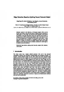
2 Multi-FPGA DesignX'low Before we begin with the hardware design for the image processing algorithm, we have to study the algorithm and evaluate the results on sample images. The algorithm is simulated in the C environment and output images will be used later on for comparison with hardware simulation, as presentedin Figure l.
I Introduction Edgedetectionis frequentlyusedlow level computer vision operationwith the goal of exfractinggeometric information from digital images []. In computer vision systems with real-time image processing requirements, we have to use specializedhigh speed processorsor ASIC circuits [2,3]. ASIC circuits, however, require extensive designing and manufacturingefforts leadingto long productiontime and financialrisks. An alternativesolutionare FPGA integratedcircuits [4]. Reconfigurable systemsbased on FPGA integrated circuits are used for fast prototypingimplementations of the completereal-time designs [5,6]. tn the edgedetectionprocess,we aresearchingfor boundariesof objects in the imagedistinguishedby quick changesof intensity(brightness).Most of the Figurel: Designflow on multi-FPGAsystem edgedetectionoperatorsare local operatorswherethe same procedure is repeatedly applied to all image The digital circuit for implementationof the pixels. Local operatorsare specificallysuitablefor algorithm is first described and simulated ul implementationwith digital circuits in pipeline behavioralVHDL. The high level VHDL structures architecture. allow fast circuit designand simulationof the circuit on sampleimages.For the simulationpurposeswe We will presentdesignand implementation of the createdtest benchwhich readsinput pixels from an digital circuit for the two well known edgedetection
,'ELECO'99INTERNATIONALCONFERENCEON ELECTRICALAND ELECTRONICSENGINEERING"
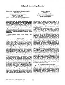
ASCII imagefile and writes output pixels to output searchingof local gradient maximums. Figure 3 thebasicstepsfor edgedetection. fite. The ASCII image files are visualizedwith C presents programs and can be converted from/to standard imageformats.This environmentenablescomparison of the imagesobtained by hardwaresimulation with theimagesobainedby algorithmsimulation. The next step is transformationof the behavioral VHDL to synthesizeableVHDL and in the sametime, partitioning of the circuit according to the target implementationplatform. The targetplatform consists of reconfigurablemodulescontainingXilinx FPGA devices(XC4008Eand XC40I0E) and staticmemory in Figure2. circuits,aspresented
Figure3: Cannyedgedetectionalgorithm The first step is smoothing the image with Gaussianfilter followedby computationof gradientin horizontal and vertical direction. Gradient magnitude is thenobtainedasa sumofsquaresofboth gradients. In the processof nonmaximumsuppressiononly the localgradientmagritudemaximumsarepreserved. In the last step,we use thresholdmechanismin orderto removesmallerpeaksof magnitude.Canny algorithmusesdoublethresholdfilter. Pixelswith the Image processing circuits in the pipeline magnitudeabovehigh thresholdare classifredas edge architecturerequire a lot of local memorycircuits for pixels. Pixels which have the magnitudeabovelow holding entire image row or several rows in the threshold and are connectedto edge pixels are also pipeline.Eachmodulecontainsfor this purpose64k x classified as edge pixels. Threshold filter uses a l6bits of fast static memory. Extemal memory recursiveprocedurein orderto find all edgepixels. areprovidedif largeramountof memoryis connectors required. 3.1CannyCircuit Architecture Figure2: Modularmulti-FPGAsystem
The processof circuit partitioning,synthesisand technology mapping is repeated until the circuit partitions fit into the reconfigurable modules and are satisfied.Whenthe circuit is timing requirements implemented in the reconfigurable module, we perform a hardwareverification. A PC with a parallel port interfaceconnectedto the reconfigurablemodule is used for hardwareverification of the emulated circuits.
Figure 4 presentsthe circuit architecture for onedimensional convolutionwitb Gaussianvector(1, 3, 4, 3, l). The presentedcircuit has minimal critical path throughaddersandmultipliers.
The hardwareverificationprocedureis similar to the simulation, but runs much faster since the operationsare performedin hardwareand PC is used only for datatransfer.The reconfigurablemodulesare finally connectedin seriesas presentedin Figure 2, system. formingthereal-timeimageprocessing
3 CannyEdgeDetector
Figure4: One-dimensional Gaussianconvolution
The Canny algorithm is frequently used for edge detectionon digital images[7, E]. The algorithmis basedon computationof gradienton digital imageand
The circuit accepts8 bit input data. The exact amountof requiredbits for intermediateresulb werc computedin order to decreaseareaand increasespeed
]86
"ELECO'99INTERNATIONALCONFERENCEON ELECTRICALAND ELECTRONICS ENGINEERING"
of the circuit. In order to normalizethe Gaussianfilter outputto 8 bits, we have to add a divider by sum of coefficientsat the end of the circuit. The complete Gaussianconvolver consists of two equal onedimensional convolvers and memory for holding intermediateimagein the pipeline. The circuit for computation of local gradient is presented in Figure5. A FIFO memoryin the sizeof one imageline is requiredfor computationof vertical gradient.
Figure5: Circuit for gradientcomputation
For each magnitude pixel M[i, j], we choose betweenits eight neighborsthe pixel closestto the gradient direction @, q) and mark it as M+. Similarly we find the neighborpixel in the opposite direction and mark it as M-. The pixel M[r, .1] is local maximumwhen: (M >M' nM 2M-)v (M > M- ^M >M+)
The inputpixelsare 8 bit unsignednumbers,while the gradientsare signed numbers.For obtaining the conectresults,we haveto extendthe input datato 9 bitsbeforecomputationof difference.
Each magnitude pixel, which is not Iocal maximum,is giventhe value0.
For the coding of magrihrdewhich is a sum of squaresof 8 bit numbers,we would need 17 bits. Experimentallywe found out that usingonly lower 8 bitsandsaturationmechanismis sufticientmostof the time. The resultsof squarecomputationare cut to t bits and if more bits are required,tlremaximum8 bit number(255)is used.
The circuit architecture for nonma: