West Palm Beach, Florida. January 2009. Designing a Preliminary Multifunctional Artificial Reef to. Protect the Portuguese Coast. M. ten Voordeâ â¡, J.S. Antunes ...
Journal of Coastal Research
25
1
69–79
West Palm Beach, Florida
January 2009
Designing a Preliminary Multifunctional Artificial Reef to Protect the Portuguese Coast M. ten Voorde†‡, J.S. Antunes do Carmo‡, and M.G. Neves† † IMAR-Institute of Marine Research University of Coimbra Department of Civil Engineering 3030-788 Coimbra, Portugal
‡ NPE/DHA National Civil Engineering Laboratory Avenida do Brasil, no. 101 1700-066 Lisbon, Portugal
ABSTRACT TEN VOORDE, M.; ANTUNES DO CARMO, J.S., and NEVES, M.G., 2009. Designing a Preliminary Multifunctional Artificial Reef to Protect the Portuguese Coast. Journal of Coastal Research, 25(1), 69–79. West Palm Beach (Florida), ISSN 0749-0208. Portugal is one of many countries in the world that suffers from coastal erosion. Conventional ways of protecting a coastline appear to entail some disadvantages. An innovative and interesting way of protecting a local coastal zone by means of multifunctional artificial reefs avoids some of them. A multifunctional artificial reef is a submerged breakwater which, besides helping to protect the local coastline, can have other purposes; in particular it may enhance the surfing possibilities and the environmental value of the local area. The structure has several positive side effects: first, it provides an unimpaired visual amenity; second, it offers tourist and economic benefits by improving the surfing conditions. A preliminary design, achieved step-by-step, is proposed for a multifunctional artificial reef making use of the theory and state of the art multifunctional artificial reef design, a preliminary design, achieved step-by-step, a priliminary design is proposed. The proposed reef geometry, together with numerical and physical tests, allows the analysis of a multifunctional reef breakwater designed to protect a stretch of the northwestern coast of Portugal. Taking into account the condition that the proposed geometry will only function properly on a sea slope bottom of less than 1 : 50, the main choices are as follows: the upper part of the structure is delta shaped with an angle of 66⬚ and a side slope of 1 : 10, and the lower part consists of a platform whose slopes are as steep as possible. The position of the reef should be such that the distance from the apex of the structure to the undisturbed shoreline is greater than 1.5 times the natural surf zone width. ADDITIONAL INDEX WORDS: Multifunctional artificial reefs, surfability, coastal protection, geotextile sand containers.
INTRODUCTION The economic importance of coastal zones has been growing in the past few decades, for a variety of reasons, including an increase in the population and related economic activities established near the coastlines, and an increase in the number of visitors wanting to enjoy a sandy beach on their holidays and practice outdoor sports such as surfing, sailing, fishing, etc. Unfortunately, many coastal zones are now suffering from erosion, and the aspects and qualities that make the coasts so attractive could be among the causes of their gradual destruction. In Portugal, there are many examples of coastline erosion. Some are due to natural causes and the reduction of sediment supplied from the updrift areas, as in the Estela area on the northwestern coast. Others mainly occur due to human activities, as in Leirosa on the northwestern coast and Vale do Lobo on the southern coast. In Estela, dredging and morphological changes in the Ca´vado River basin have led to dune erosion (VELOSO GOMES et al., 2006). In Leirosa, the construction of an underwater effluent outlet damaged the continuity of the existing sand dune system (ANTUNES DO CARDOI: 10.2112/07-0827.1 received 12 January 2007; accepted in revision 10 January 2008.
MO,
SCHRECK REIS, and FREITAS, 2006; SCHRECK REIS, ANCARMO, and FREITAS, 2005). In Vale do Lobo, the erosion is a direct consequence of the construction of the Vilamoura Marina and the Quarteira coastal defences, as well as golf course watering (VELOSO GOMES et al., 2006). Generally, it can be said that beach erosion, the need to protect natural and constructed heritage, and the degradation of environmental and species habitats are the main problems to be solved in order to protect the coast and its fragile environment. There are several conventional methods to protect a coast from erosion, such as groins, detached breakwaters, seawalls/ revetments, artificial dunes, and sand supply. Even though these methods adequately solve the local erosion problem in some cases, they have disadvantages. Sand supply and artificial dunes are in most cases an additional measure and not a primary solution for coastal erosion. The drawback of emerged breakwaters, groins, and seawalls/revetments is their large visual impact, because local people and tourists ask for an unimpaired visual amenity. One shortcoming of groins is the large amount of downdrift erosion when there is an alongshore current along the coastline. The material most often used in coastal structures up to now is rubble mound. However, because of a shortage of natural rock, these structures are very expensive to build and maintain.
TUNES DO
70
ten Voorde, Antunes do Carmo, and Neves
In this context, a complete and effective coastal defence should take into account the economic, social, and environmental effects of the solution for the global problems concerned. Consistent, broad solutions of those problems should be the goal. A relatively new approach to protecting a coast is a multifunctional artificial reef (MFAR), a submerged breakwater that has several purposes. In addition to protecting the local coastline and improving the surfing possibilities, an MFAR can enhance the environmental value of the area where the reef is built. An MFAR does not have the failings of the above-mentioned conventional coastal protection measures: its visual impact is low since it is submerged, and with a proper design the downdrift erosion can be minimal. The environmental value can be enhanced due to the fact that MFARs can be made from geotextile sand containers (GCSs), which are a more cost-effective constructive solution than rubble mound. They provide an excellent substrate for marine flora and the development of a diverse ecosystem when they are below the water level (JACKSON et al., 2004). Geotextile sand containers can be installed more cheaply and quickly than other technical solutions since the filling materials can be introduced in situ by hydraulic pumping (YOUNG as cited in OH and SHIN, 2006). Another benefit is that GSCs covered with a predominately ‘‘soft’’ vegetation layer are safer for surfers than rubble mound units. This material has already been used in several submerged shore protection structures, such as the Narrowneck Reef, an MFAR off the Gold Coast, Australia (JACKSON et al., 2005), and in a submerged detached breakwater system off the eastern Korean shoreline (YOUNG as cited in OH and SHIN, 2006). Even though MFARs have already been built in some parts of the world and are a promising way of protecting a coastline with an improvement of surfing possibilities, the design evolution of an MFAR has not been adequately described, starting with the theory. In addition, there is no stepwise design ‘‘guide’’ to all the key parameters that determine the geometry of a reef. HENRIQUEZ (2004) found that the peel angle has a maximum for the wave angle in deep water. Because of this, the geometry of the reef is forced to take a certain form in order to be surfable. However, a theoretical explanation for the phenomenon of a maximum peel angle that takes into account the effects of shoaling and refraction was not given. SMIT and MOCKE (2005) found that, in the design evolution of an artificial surfing reef for the coast of Dubai, a reef that creates good, surfable waves should allow them to shoal prior to breaking without undergoing significant refraction; therefore, a platform is included in the reef design. A platform had been discussed before in the bathymetric classification of quality surfing breaks by M EAD and BLACK (2001a). However, the influence of the platform on other surfability parameters besides the peel angle has not yet been described from a theoretical point of view. Wave focusing is recognised as an important aspect in the design of an MFAR (HENRIQUEZ, 2004; MEAD and BLACK, 2001; SMIT and MOCKE, 2005). In addition to increasing the wave height and refraction, it has an effect on the peel angle. The contribution of refraction and wave focusing on the peel angle along the breaker line has not yet been described.
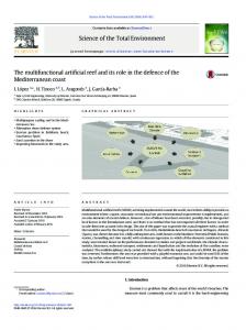
Figure 1. Peel angle.
The objective of this paper is to present the design steps of a preliminary MFAR which creates good surfable waves and protects the local coastline in the northern part of Portugal. With this preliminary design, numerical and physical tests can be performed to investigate the capability of an MFAR to enhance the surfing possibilities and to protect a specific local coastline. The presented design steps are based on the theory and the state of art of MFAR design, followed by general conclusions. First a description of the theoretical background used in the definition of the geometric characteristics of MFARs is given.
THEORETICAL BACKGROUND An MFAR has two effects with respect to coastal protection. As with any conventional shore-parallel breakwater, one effect is a reduction in the wave energy that reaches the coast, and thus the impact on the basic dune system. The other effect is attributable to the broad crest of an MFAR, which may cause wave rotation as the waves approach the coast. This wave rotation has two consequences: (1) deflecting and stretching the wave crest, reducing the wave energy; and (2) aligning the wave to the shore, reducing the wave-driven currents and thus the sediment transport along the shore. These two effects make an MFAR an interesting form of coastal protection. However, it is not enough to design an MFAR to prevent erosion: the aspect of creating good waves for surfing has to be taken into account. This section gives a systematic explanation of the key surfing parameters used in the design of an MFAR, i.e., the peel angle, the wave height, and the breaker type. The chosen design values will also be elucidated. The peel angle is the angle enclosed between the wave crest (normal on the wave ray) and the breaker line, angle ␣ in Figure 1 (WALKER, 1974). If the breaker line is parallel to the reef bathymetry, angle ␣ is equal to the wave angle  (Figure 1) between the normal to the reef bathymetry and the wave ray at the breaking point. There are several important conditions required for surfing, which are related to the peel angle, the wave height at the breaking point (Hb), and the breaker type. HUTT, BLACK, and MEAD (2001) devised a classification of surfing skill (from 1 to 10) rated against peel angle and wave height. The purpose is to design a reef for surfers with skill 3–6 according to that classification. This means that the peel angles should be larger than 40⬚ and that
Journal of Coastal Research, Vol. 25, No. 1, 2009
Designing a Preliminary Multifunctional Artificial Reef
71
Figure 2. Path of the wave compared to the normal on the depth contours.
Hb should be larger than 0.6 m. In addition, the wave should be plunging with a relatively low inshore Iribarren number, b. The Iribarren number is defined by:
b ⫽
tan ␣
冪
(1)
Hb L0
where tan ␣ is the slope that the wave experiences (instead of the slope of the normal on the reef contours; see Figure 2), Hb is the wave height at the breakpoint, and L0 is the wavelength in deep water. At the start the wave should even have a b value slightly higher than the value at the transition of spilling and plunging, because it is then easier to start surfing. This paper presents design steps for a reef that will be good for amateur surfers (skill levels 3–6) but that will also be as interesting as possible for professionals, so that championships may eventually be an option. Because of the design, Hb is chosen to be 2 m, the design peel angle is 40⬚, and the breaker type is at the transition of spilling and plunging (with relatively low values of b). Depending on the refraction and shoaling, the design wave height in deep water (H0) is equal to, smaller, or larger than 2 m. On an open coast with relatively small incidence wave angles (less than 45⬚), like the Portuguese west coast, H0 will be equal to or at most two times smaller than Hb. Here a design H0 of 1.5 m is assumed. The range of 1–2 m is the most common significant wave height in deep water off Portugal’s northwest coast, so the value of the design wave height H0 is good in terms of both quality and quantity. It should be noted that in this paper the Iribarren number is taken as the characteristic parameter for the breaker intensity. MEAD and BLACK (2001) found another indicator for the intensity of plunging wave breaking. However, since their method does not yet take wave height and period into account, this paper adopts the Iribarren number. The theoretical background of the peel angle on an MFAR is discussed below. HENRIQUEZ (2004) has shown that, according to linear the-
Figure 3. Peel angle ␣ as a function of the wave angle s and the shelf depth khs or hs for T ⫽ 10 s, H0 ⫽ 1.5 m.
ory and taking into account the effects of shoaling and refraction, the relation between the peel angle, ␣, and angle (Figure 1) is represented by the graph in Figure 3. The results shown in Figure 3 are for a 10-s period and a wave height in deep water of 1.5 m. The calculations were made for waves travelling over a shelf before reaching the reef (Figure 4b). However, the results are the same for a wave travelling over a sloping bottom before reaching the reef, as long
Figure 4. (a) Peel angle without shelf; (b) Peel angle with shelf.
Journal of Coastal Research, Vol. 25, No. 1, 2009
72
ten Voorde, Antunes do Carmo, and Neves
Figure 7. Two cases of reefs starting at different depths. Figure 5. The counteracting effect of the longer continuation of refraction and the effect of a large angle .
as angle , the depth at the start of the reef, and the wave height in deep water are the same (Figure 4a). The peel angle has a maximum for angle of 66⬚, regardless of wave conditions. This phenomenon is explained in TEN VOORDE, ANTUNES DO CARMO, and NEVES (2006) by the counteracting effect of the longer continuation of refraction and the effect of a larger angle . Figure 5 shows the counteracting effect for a wave travelling from deep water towards the shoreline. In this figure, the angle of incidence in deep water (0) is equal to angle in Figure 1, and the angle in the third column, at the position of the breaker line position, is equal to peel angle ␣ in Figure 1. Another aspect of the peel angle is that it has exponential growth with decreasing depth of the start of the reef for the same wave angle (TEN VOORDE, ANTUNES DO CARMO, and NEVES, 2006), as can be seen in Figure 3. The same submergence is assumed. The reason for this exponential growth is explained below. The only process by which the wave angle changes along the wave ray when a wave travels from deep water towards the shoreline is refraction. The influence of refraction on the wave angle is given by Snellius’s law:
冢 冣
d sin ⫽0 dx c
(2)
where dx is in the direction of the wave ray, is the wave angle between the wave ray and the normal to the bathym-
Figure 6. Relative refraction.
etry, and c is the wave velocity. Equation (2) can be rewritten as: sin 2 ⫽ A sin 1
A⫽
tanh(kh)2 tanh(kh)1
(3)
where k is the wave number, and the water depth h1 (h in (kh)1) is greater than the water depth h2 (h in (kh)2). The value of A in Equation (3) is plotted in Figure 6 for different water depths. The difference in the water depth from point 1 to point 2, ⌬h ⫽ h1 ⫺ h2, is assumed to be the same for every water depth. In fact, the value of A in Equation (3) gives information about the magnitude of refraction. It can thus be seen in Figure 6 that refraction for the same ⌬h is relatively greater in shallower water. In order to show this effect on the exponential growth of the peel angle with decreasing depth, two cases are assumed (Figure 7):
● Case 1: two reefs in relatively deep water, starting with a difference of ⌬h in water depth ● Case 2: two reefs in relatively shallow water, starting with a difference of ⌬h in water depth In Case 2 the loss in total refraction of the wave from to peel angle ␣ between the two reefs is larger than in Case 1 (as can be seen in Figure 8, where ⌬x is the horizontal distance for the vertical distance ⌬h). This means that the wave at the breaking point has refracted relatively less in Case 2 than in Case 1, leading to a stronger growth of the peel angle. This effect appears at every water depth, and it is the reason that the peel angle experiences an exponential growth with decreasing depth for the same wave angle . So it can be said that the peel angle grows exponentially for a lower depth of
Figure 8. Different loss in refraction for the two cases in Figure 7.
Journal of Coastal Research, Vol. 25, No. 1, 2009
Designing a Preliminary Multifunctional Artificial Reef
73
Figure 10. a) Angles ␣1 and ␣4; b) Angle ␣3.
● ␣1 is angle minus the decrease due to refraction on the reef slope (Figures 9b and 10a). ● ␣2 is the difference of the angles for the cases with and without wave focusing, due to less refraction by earlier breaking (see ␣2 in Figure 9b; ␣2 ⫽ ␣4 ⫺ ␣1 in Figure 10a). ● ␣3 is the angle due to deviation of the breaker line from the parallel to the bathymetry of the reef side (Figures 9b and 10b).
Figure 9. (a) Breaker line (Henriquez, 2004); (b) Contributions to the peel angle along the breaker line (basic figure: Henriquez, 2004); (c) Enlargement of part of the breaker line; schematic positions of certain values of the peel angle.
the start of the reef with the same angle because refraction is exponentially greater in shallow water. In addition to refraction, wave focusing is another physical process that has a large influence on the peel angle. If wave focusing occurs, the wave rays converge, leading to an increase in wave height and consequently the wave’s earlier breaking. This causes the breaker line to be nearer the intersection of the reef and the sea bottom than if there was no wave focusing, leading to less refraction and thus a higher value of the peel angle. When wave focusing occurs, the value of the peel angle can be divided into several contributions (Figures 9 and 10):
The breaker line in Figures 9a and 9c and the graph in Figure 9b can be divided into three parts: area A, where wave focusing occurs; area B, where wave defocusing occurs; and area C, where there is neither wave focusing nor defocusing (␣2 and ␣3 are zero, Figure 9b). The transition from wave focusing to wave defocusing occurs at the minimum of angle ␣1 ⫹ ␣2 on the right side of area A. This can be concluded because at that point the peel angle is equal to ␣1 (which is the value for the peel angle if there is no wave focusing). The peel angle ␣1 is different for areas A and B. In area A, ␣1 is the minimum value of ␣1 ⫹ ␣2, corresponding to a peel angle value when no wave focusing would occur. For large values of s (distance along the breaker line, starting at the reef tip), the peel angle reaches a constant value. This is the value of ␣1 in area B, which would occur if there was no wave focusing and no wave defocusing. In area A, ␣1 is smaller than in area B. This means that the position of the minimum of ␣1 ⫹ ␣2 at the right end of area A is nearer the crest level of the reef than the location of the peel angle for large values of s in area C (Figure 9c). Angle ␣2 is positive in area A and negative in area B (Figure 9b). The value is positive in area A because the breaking
Journal of Coastal Research, Vol. 25, No. 1, 2009
74
ten Voorde, Antunes do Carmo, and Neves
Table 1. Peel angles for a reef with a submergence of 1.5 m. a. Platform Depth of 4.0 m
b. Platform Depth of 5.0 m
T\H
1m
2m
3m
4m
T\H
1m
2m
3m
4m
6s 10 s 14 s
* * -
35.7 38.6 41.8
44.6 49.5 x
x x
6s 10 s 14 s
* * -
31.9 33.8 36
39.1 41.8 45.3
x x
Bold values ⫽ wave breaks on the reef; * ⫽ waves go over the reef; x ⫽ wave has already broken or breaks on the beginning of the platform; - ⫽ rarely existing wave conditions on the west coast of Portugal, T/H ⫽ period/wave height.
occurs further away from the crest level of the reef than it would be if there was no wave focusing. The value in area B is negative because the breaking is positioned nearer the crest level of the reef than it would be if no wave focusing and no wave defocusing occurred.
PROPOSED STEPS FOR THE PRELIMINARY DESIGN OF AN MFAR FOR THE NORTHWESTERN PORTUGUESE COAST As mentioned before, an MFAR should fulfil conditions related to coastal protection and good surfability of the waves over the structure. With regard to these two aspects, the design of an MFAR has the following key parameters: MFAR angle (; see Figure 1), height of the reef, reef geometry, submergence of the reef, horizontal dimensions, and slope of the reef. These key design parameters are discussed next, and limitations for each parameter are presented.
MFAR Angle The choice of MFAR angle is mainly related to the peel angle. As described in the section ‘‘Theoretical Background,’’ the peel angle has its maximum for an MFAR angle equal to 66⬚, which is then the value taken for the MFAR angle. Depending on reef geometry, this angle could be constant or variable along the reef side.
Height of the Reef The height of the reef depends on its horizontal dimensions, its distance from the shore, its submergence, and its slopes. However, the height needs a minimum value in relation to the breaker type. For a certain reef slope, the height determines the length of the reef side. This length should be large enough for the wave to feel the reef. If not, the wave will not have enough space and will also break according to the slope of the bottom. This leads to the design choice of a reef side at least one-fourth times the local wave length, since the breaker type is assumed to be created in one-fourth of the local wave length. This means that for a relatively high wave period of 14 s and a reef start beginning at a depth of 4 m, the minimum length is 22 m. Assuming a slope of 1 : 10, the minimum height is then 2.2 m for waves breaking on the crest of the reef. For the guideline, an extra value of 0.3 m is added, so waves can also break a little before reaching the crest, giving a minimum height of 2.5 m. For smaller wave periods a lower reef height should achieve the design breaker type. Numerical simulations will be needed to determine the exact length of the reef side required for the proper breaker
type as a function of the wave length and, consequently, the reef height. The research of SMITH and KRAUS (1991) concerns the influence of length of the reef slope on the breaker type. They did a laboratory study of wave breaking over bars and artificial reefs. They used the results to categorise the offshore breaker type differently from BATTJES (1974) when the bottom has a barred profile. This categorisation is not used by the authors of this paper because it is general; varying reef slopes and wave conditions and the length of the reef slope are not taken into account.
Geometry of the Reef The choice of geometry is, like the choice of MFAR angle, mainly related to the peel angle. An initial design choice for the geometry shape is a delta form composed of two rides (a left and a right ride) with a constant MFAR angle equal to 66⬚, as the peel angle has its maximum for ⫽ 66⬚ (Figure 1). This maximum peel angle is according to linear refraction, however, and does not take into account the wave focusing at the tip of the reef. In order to get the proper form regarding the design peel angle, numerical simulations that take irregular waves and wave focusing into account will have to be performed. This delta structure, which will be designed to create surfable waves, could be placed on the sea bottom or on a platform. The choice of a platform is definitely positive for the coastal protection aspect of the reef, because it makes the (large) waves break over it along its whole width (SMIT and MOCKE, 2005). It must be determined if the platform has a positive influence regarding the surfer parameters of peel angle (␣), breaker type (here related to the corresponding inshore Iribarren number, b), and wave height at the breaking point (Hb). As mentioned before, the peel angle should be between 40⬚ and 60⬚ for the waves to be surfable, and the peel angle has a maximum for an MFAR angle of 66⬚. Some calculations have been made to gain more insight into peel angle values. To estimate the peel angle it is important to know what the design wave height is. The larger the design wave height the smaller the peel angle will be (the wave breaks sooner and so refracts less). Calculations (Table 1) were performed for a reef consisting of a platform with a delta structure on top, and having an MFAR angle of 66⬚ and a breaker criterion of Hb ⫽ 1.1hb. Over mild slopes, waves are expected to break when Hb ⫽ ␥hb, where Hb is the breaker height, hb is the breaking depth, and ␥ is equal to 0.78 (SVERDRUP and MUNK, 1946). As the beach slope increases, as though over a reef, the value of ␥ increases for the same wave steepness in deep
Journal of Coastal Research, Vol. 25, No. 1, 2009
Designing a Preliminary Multifunctional Artificial Reef
75
water. The chosen value of ␥ of 1.1 is based on the work of KAMINSKY and KRAUS (1993). These researchers derived the following empirical formula in a review of 17 data sets obtained by various investigators in laboratory experiments:
␥b ⫽ 1.20 ⬁0.27
(4)
where ␥b is the breaker condition and ⬁ is the deep water breaker parameter. The value of ⬁ is equal to b with the exception that the breaker wave height has to be replaced for the wave height in deep water (H0). Assuming a reef slope of 1 : 10, the mean value of ␥b for periods of 6, 10, and 14 s and wave heights of 1, 2, 3, and 4 m (these are the tested wave conditions) is 1.1. The maximum is 1.3. For safety reasons the submergence of the reef is 1.5 m, as described in the section ‘‘Submergence of the Reef.’’ Two depths for the platform were chosen: 4.0 m, the minimum depth of the platform (1.5-m submergence ⫹ 2.5-m minimum height of the delta structure), and 5.0 m (Table 1). Waves that break before they have travelled a length equal to the 1.0-m height of the delta are not taken into account, because they are not expected to result in plunging waves. In fact, this value of 1.0 m is less than the minimum height of the reef, that the waves should experience (as explained in the section ‘‘Height of the Reef’’ ), but that is because, for wave periods less than 14 s, the breaker type is expected to be plunging with less height. Although the calculations use linear theory and wave focusing is not taken into account, they do give an indication about the values of the peel angle. Tables 1a and 1b show that for the range of 1–2 m, a platform with a minimum depth of 4.0 m offers in more conditions peel angles within the range of amateurs, i.e., between 40⬚ and 60⬚. When the platform is lower than 5.0 m, the peel angles will be even lower than the values shown in Table 1b. As the peel angle values are better (Table 1) for the depth of the delta structure at the start that is as small as possible, it can be concluded that a platform at the seaward end of the structure definitely has a positive influence on the peel angle. However, if the platform is under the whole delta structure, it probably has a relatively negative influence on the peel angle at the shoreward end when compared to the absence of a platform, because the delta structure can be higher at this part. Moreover, the influence of a platform on the breaker type and the wave height at the breaking point has not yet been investigated. In order to analyse these influences, the qualitative development of the peel angle (), the inshore Iribarren number (0), and the wave height at the breaking point (Hb) along the breaker line are presented with and without a platform under the delta structure. The development of ␣, 1/b, and Hb is presented in Figure 11 and shows that, in the absence of a platform, ␣, 1/b, and Hb are smaller at the beginning of the reef and larger at the end. These differences are caused by more refraction at the beginning of the reef (by longer slope) and less refraction at its end (by shorter slope). When wave focusing no longer plays a role, ␣, b, and Hb increase towards the end of the reef without a platform and stay constant when a platform is present. From this analysis, it can be concluded that the choice of a platform has an influence on the surfer parameters of peel angle, breaker type, and wave height. Wave defocusing is not
Figure 11. Relative development of peel angle, wave height, and Iribarren number along the breaker line.
taken into account in this analysis, for two reasons: first, because the area over which the wave defocusing occurs is relatively small; and second, because the contributions to the peel angle of wave defocusing are relatively small compared with the area where wave focusing occurs, as described in the section ‘‘Theoretical Background.’’ The conclusion regarding the choice of a platform will be described first for the peel angle. A small variation in the peel angle along the ride does not present a problem since surfers actually like some variation. However, the peel angle should be between 40⬚ and 60⬚. Calculations showed that these values of the peel angle are reached with the platform at the minimum depth for most wave conditions. So in terms of the peel angle, a platform in the first part of the reef is a better option. If the height at the last part of the reef is smaller without a platform, the option of no platform would be better because refraction will be less. Regarding the breaker type, the use of a platform is again a better option, because 0 is smaller at the beginning and stays constant along the ride. The preferred wave height depends on the skill of the surfer. However, it is easier to start surfing when the wave is somewhat higher at the beginning, especially when the peel angle is small. So it can be concluded that for wave height, a platform is a good option, since for this case the wave is higher at the beginning of the reef. In conclusion, the use of a platform has a positive influence on the most important surfer parameters: peel angle, breaker type, and wave height. However, not using a platform is more positive for the peel angle if the reef is less high, even though it should be higher than the minimum, as stated in the section ‘‘Height of the Reef.’’ Constructing a platform only at the seaward part of the delta structure would give a maximum peel angle along the entire ride. In some cases this is actually the only possibility, because the platform intersects with the bottom (Figure 12). Positioning the reef more seaward in order to construct a platform under the whole delta is often not an option since, as will be explained in the section ‘‘Horizontal Dimensions,’’ the distance between the shoreline and the structure is established in order to prevent coastline erosion. The form of the platform in the horizontal plane should be chosen so that its volume is as small as possible.
Journal of Coastal Research, Vol. 25, No. 1, 2009
76
ten Voorde, Antunes do Carmo, and Neves
Table 3. Maximum reef heights for different bottom slopes. Distance from Shoreline (m)
1 : 25
1 : 50
1 : 75
1 : 100
175 250
5.5 m 8.5 m
2.0 m 3.5 m
0.8 m 1.8 m
0.3 m 1.0 m
Figure 12. Intersection of platform and bottom.
Submergence of the Reef The submergence of the reef is determined by two factors. First, the submergence should be shallow enough for the design waves to break on the reef. Second, it should be deep enough to be safe for surfers. With regard to the first factor, the submergence is dependent on the design breaking wave height and the breaking condition. Assuming a critical breaking condition of Hb ⫽ 1.3h, which gives the smallest breaking depth, the submergence of the reef with a design breaking wave height of 2.0 m is 1.5 m. Concerning the second factor, it is a known fact that the water depth during backflow under the wave trough could be very shallow, and the reef may even become emerged (‘‘suck dry’’). However, surfing is a sport that involves risks. Surfers know that, and most of them develop their own way to see if they can surf a certain section safely. Nonetheless, safety should be considered in the design. For diving in pools, FINA (Fe´de´ration Internationale de Natation [International Swimming Federation]) regulations suggest 1.8 m as an acceptable depth for submergence (CORBETT, TOMLINSON, and JACKSON, 2005). But surfers tend to fall off their boards rather than dive vertically, reducing both the depth of the dive and the risk of serious injury (e.g., damage to the neck and spine). This fact and the physical experiments conducted by CORBETT and TOMLINSON (2002), in which the water depth above a reef with a certain submergence was investigated for different wave heights, lead to the design choice that submergence should be deeper than the design wave height in deep water. The design wave height is 1.5 m, so the minimum submergence for safety is 1.5 m. The sucking dry phenomenon is probably hard to prevent completely, especially with high waves at low tide. Experience with the Narrowneck Reef has indicated that, with a submergence of 1.5 m, the crest containers sucked dry during larger wave conditions (⬎艐2 m) at low tide (JACKSON et al., 2005). In specific design studies, numerical simulations will be needed to verify if and for what wave heights this phenomenon occurs. It has to be mentioned that the design wave height and the corresponding design submergence are for low tide, because
this tidal level gives the critical submergence. But many coastal zones have tidal conditions, so the influence of the tide on the peel angle should not be neglected. To investigate this influence, calculations assume a tidal level 1.5 m higher than that in Table 1, so the submergence is now 3.0 m and the depths of the platform are 5.5 m and 6.5 m. Tables 2a and 2b show that in both cases the peel angles are high enough for both amateur and professional surfers, but the waves that break over the delta have an H0 of 3–4 m. By refraction and shoaling, the Hb on the reef will be even higher than 4 m. These wave heights cannot be surfed by surfers at skill levels 3 and 4. In conclusion, it can be said that higher tidal levels make surfing impossible for most amateurs. The tide also influences the breaker type by affecting the breaker wave height over the delta. Our guideline is to pay attention to the fact that just one tidal level can be the design level if the reef is designed for a certain category of surfers. The minimum height of the reef and the minimum submergence, together with the slope of the sea bottom, have a large influence a reef’s effectiveness in creating surfable waves. Table 3 shows the maximum reef heights for a reef with a submergence of 1.5 m, a distance from the base of the delta to the shoreline of 175 m, a distance from the apex of the delta to the shoreline of 250 m (see the section ‘‘Horizontal Dimensions’’), and different slopes of the sea bottom. In this case the length of the ride is about 82 m. A height of 2.0 m at the base of the reef is accepted as the minimum value. This is less than the minimum height of 2.5 m (as described in the section ‘‘Height of the Reef’’ ) because the reef will be higher further seaward where the wave rays start that reach the end of the reef. As a consequence, the criterion for the reef structure is a depth of 3.5 m at the base of the delta structure, i.e., 2.0 m as the minimum reef height plus 1.5 m from the submergence. Table 3 shows that the minimum slope value for building an artificial surfing reef that functions properly is 1 : 50. With this bottom slope the platform will be 50 m under the seaward part of the delta before it intersects with the bottom. With some simple refraction calculations, it is predicted that the wave rays at the shoreward intersection of platform and reef still reach the crest of the
Table 2. Peel angles for a reef with a submergence of 3.0 m. a. Platform Depth of 5.5 m
b. Platform Depth of 6.5 m
T\H
1m
2m
3m
4m
T\H
1m
2m
3m
4m
6s 10 s 14 s
* * -
* * *
* * 42.3
46.5 51.1
6s 10 s 14 s
* * -
* * *
* * *
41.4 44.5
Bold values ⫽ wave breaks on the reef; * ⫽ waves go over the reef; - ⫽ rarely existing wave conditions on the west coast of Portugal, T/H ⫽ period/wave height.
Journal of Coastal Research, Vol. 25, No. 1, 2009
Designing a Preliminary Multifunctional Artificial Reef
Figure 13. Wave rays reaching the crest of the delta.
delta (Figure 13). Numerical simulations have to be performed to confirm this.
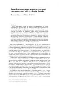
Horizontal Dimensions The horizontal alongshore dimension depends on the length of the local coastline to be protected. The cross-shore dimension of the reef breakwater depends on the design length of the ride, which is the length of the breaker line at one of the sides of the reef (Figure 9a). This dimension is limited, however. RANASINGHE and TURNER (2006) found that the principal mode of shoreline response to submerged structures can vary between erosive and accretive, depending on the offshore distance to the structure. Figure 14, left, illustrates the occurrence of erosion, as given by numerical modelling, and Figure 14, right, shows the occurrence of accretion. The test wave conditions used from Figure 14 were a peak period of 10 s and a significant wave height of 1.5 m. It was concluded that the predominant wave incidence angle and the submergence of the structure have important implications for the magnitude of shoreline response but not for the mode of shoreline response (i.e., erosion vs. accretion). Based on these results, a predictive empirical relationship is proposed as a preliminary engineering tool to assess shoreline response to submerged structures. This relationship is Sa/SZW ⬎ 1.5, where Sa is the distance from the apex of the structure to the undisturbed shoreline and SZW is the natural surf zone width. The distance Sa should clearly not be too large, because the effect of the structure on the morphodynamic processes adjacent to the shoreline will start to decline with increasing values. Even though this is a good preliminary engineering tool, it has to be ascertained whether Sa is a better characteristic cross-shore length for the mode of erosion or accretion for broad-crested structures than, for example, the distance from the base to the shoreline.
Slope of the Reef Structure A surfable wave for amateurs should be plunging, almost spilling. Based on experimental results with a 1-m wave
77
height, HENRIQUEZ (2004) found that the inshore Iribarren number (b) should be between 0.6 and 0.9 to get surfable waves. It is assumed here that this surf range is for amateur surfers (skill levels 3–6), because the breaker type is plunging with relatively small inshore Iribarren numbers. Some calculations using linear theory have been performed for different wave heights; in this way it can be analysed with which slopes the waves most frequently reaching the northwest coast of Portugal will break as a plunging breaker type. Figure 15 shows the inshore Iribarren numbers for a slope (that the wave meets) varying from 1 : 6 to 1 : 18, a wave height at the breakpoint varying from 1 to 4 m, and a wave period of 10 s. As can be seen, only some combinations of slope and wave height give a plunging breaking wave in the surf range. The values of b that lie in the surf range (given by HENRIQUEZ, 2004) are for slopes between 1 : 8 and 1 : 18, as can be seen in Table 4. It should be pointed out that the theory used is linear and that the surf range of 0.6 to 0.9 m was found in experiments for a wave height of 1 m (prototype) at the wave maker, and here it is applied to a wave height range of 1 to 4 m at the breakpoint. The design choice for the side slope of the delta structure is a value of 1 : 10 because with this slope it is expected that the design breaking wave height (Hb) of 2 m experiences slopes between 1 : 10 and 1 : 14 and that, consequently, the breaker type lies in the surf range. This will have to be verified with numerical simulations for each specific set of geometry and wave conditions. The design choice for the slope at the shoreward end of the delta structure and for the slope of the platform at all sides is that it should be as low as possible in order to minimise its volume.
CONCLUSIONS Multifunctional artificial reefs are submerged breakwaters with several purposes. In addition to protecting the local coastline, they enhance surfing possibilities and/or increase the environmental value of the area where the reef is situated. Coastal protection by an MFAR can be achieved in two ways: First, the reef breakwater can reduce the wave energy since the wave breaks along the structure. Second, the reef can rotate the waves in such a way that the longshore current is diminished, so that, for example, the dune system is less harmed by large waves in severe storms because the energy is spread over a larger area. MFARs have new promising aspects, too: they provide an unimpaired visual amenity, and they can offer tourist and economic benefits by improving the surfing conditions. Theoretical explanations have been offered for the development of the peel angle for increasing angles in deep water and for decreasing depths of the start of the reef. Furthermore, the contributions of wave focusing and refraction on the peel angle along the breaker line have been presented. And the development of the peel angle, the breaker type, and the wave height at the breaking point along the breaker line for a reef with and without a platform are given, thereby justifying the choice of a platform. Design evolution steps for a preliminary design for the
Journal of Coastal Research, Vol. 25, No. 1, 2009
78
ten Voorde, Antunes do Carmo, and Neves
Figure 14. Erosion for distance apex structure-coast of 100 m (left) and accretion for distance apex structure-coast of 250 m (right; Ranasinghe and Turner, 2006).
northwest coast of Portugal have also been presented, based on theory and the state of art:
● The reef structure consists of a delta structure with a platform. ● The delta structure: 䡩 has an MFAR angle of 66⬚; 䡩 has a side slope with a minimum length of one-fourth times the local wave length and a slope of 1 : 10. ● The platform: 䡩 has a shape such that small oblique waves are still surfable on the delta structure and do not refract on the side slopes;
䡩 has as steep a slope as possible; 䡩 has an alongshore length large enough to protect the local coastline from suffering erosion; 䡩 requires attention in relation to where the platform can be extended under the delta structure. ● The distance from the apex of the structure to the undisturbed shoreline should be greater than 1.5 times the natural surf zone width. Additionally, attention has to be paid to the influence of tidal levels on the peel angle, breaker height, and breaker type of the waves breaking over the delta structure. This preliminary design, together with numerical and physical tests, will permit analysis of the capacity of an MFAR breakwater to protect a local coastline on the northern
Table 4. Inshore Iribarren number for different slopes and wave heights in the surf range. Tan ␣
Hb (m)
b
1:8 1 : 10
4 2 3 4 2 3 2 1 1
0.79 0.89 0.73 0.63 0.74 0.61 0.64 0.79 0.70
1 : 12
Figure 15. Surf range.
1 : 14 1 : 16 1 : 18
Journal of Coastal Research, Vol. 25, No. 1, 2009
Designing a Preliminary Multifunctional Artificial Reef
coast of Portugal and to enhance the area’s surfing possibilities.
ACKNOWLEDGMENTS The authors gratefully acknowledge the Portuguese Foundation for Science and Technology under the project PTDC/ ECM/66516/2006 and the financial sponsorship of M.Sc. ten Voorde’s Ph.D. research by the Instituto de Investigac¸a˜o Interdisciplinar, Coimbra, Portugal.
LITERATURE CITED ANTUNES DO CARMO, J.S.; SCHRECK REIS, C.S., and FREITAS, H., 2006. Successful rehabilitation of a sand dune system. In: Proceedings of the Sixth International Conference on Environmental Problems in Coastal Regions Including Oil and Chemical Spill Studies (Rhodes, Greece), WIT Transactions on Ecology and the Environment (88), pp. 195–204. BATTJES, J.A., 1974. Surf similarity. In: Proceedings of International Conference on Coastal Engineering (Copenhagen, Denmark), pp. 466–479. CORBETT, B.B. and TOMLINSON, R., 2002. Noosa Main Beach Physical Modelling. Griffith Centre for Coastal Management Research Report No. 17. CORBETT, B.B.; TOMLINSON, R.B., and JACKSON, L.A., 2005. Reef breakwaters for coastal protection safety aspects and tolerances. In: Coasts and Ports: Coastal Living—Living Coast, Proceedings of the Australasian Conference 2005 (Adelaide, Australia), pp. 673–678. HENRIQUEZ, M., 2004. Artificial Surf Reefs. Delft, The Netherlands: Delft University of Technology, Master’s thesis, 53p. www. waterbouw.tudelft.nl (accessed August 18, 2006). HUTT, J.A.; BLACK, K.P., and MEAD, S.T., 2001. Classification of surf breaks in relation to surfing skill. Journal of Coastal Research, Special Issue No. 29, pp. 66–81. JACKSON, L.A.; REICHELT, R.E.; RESTALL, S.; CORBETT, B.; TOMLINSON, R., and MCGRATH, J., 2004. Marine ecosystem enhancement on a geotextile coastal protection reef—Narrowneck reef case study. In: Proceedings of the 29th International Conference on Coastal Engineering (Lisbon, Portugal), pp. 3940–3952. JACKSON, L.A.; TOMLINSON, R.; TURNER, I.; CORBETT, B.; D’AGATA, M., and MCGRATH, J., 2005. Narrowneck artificial reef; results of 4 yrs monitoring and modifications. In: Proceedings of the 4th In-
79
ternational Surfing Reef Symposium (Manhattan Beach, California). www.coastalmanagement.com.au (accessed August 17, 2006). KAMINSKI, G. and KRAUS, N.C., 1993. Evaluation of depth-limited wave breaking criteria. In: Proceedings of 2nd International Symposium on Ocean Wave Measurement and Analysis (New Orleans, Louisiana), pp. 180–193. MEAD, S.T. and BLACK, K.P., 2001a. Field studies leading to the bathymetric classification of world-class surfing breaks. Journal of Coastal Research, Special Issue No. 29, pp. 5–20. MEAD, S.T. and BLACK, K.P., 2001b. Predicting the breaking intensity of surfing waves. Journal of Coastal Research, Special Issue No. 29, pp. 51–65. OH, Y.I. and EUN CHUL SHIN, 2006. Using submerged geotextile tubes in the protection of the E. Korean shore. Journal of Coastal Engineering, 53, 879–895. RANASINGHE, R. and TURNER, I.L., 2006. Shoreline response to multi-functional artificial surfing reefs: a numerical and physical modeling study. Journal of Coastal Engineering, 53, 589–611. SCHRECK REIS, C.; ANTUNES DO CARMO, J.S., and FREITAS, H., 2005. Leirosa Sand Dunes: a case study on coastal protection. In: Proceedings of the Maritime Transportation and Exploitation of Ocean and Coastal Resources (Lisbon, Portugal), pp. 1469–1474. SMIT, F. and MOCKE, G., 2005. Physical and numerical modelling of morphological and surf parameter response to an artificial reef. In: Proceedings of the 4th International Surfing Reef Symposium (Manhattan Beach, California). SMITH, E.R. and KRAUS, N.C., 1991. Laboratory study of wave breaking over bars and artificial reefs. Journal of Waterway, Port, and Coastal Engineering, 117(4): 307–325. SVERDRUP, H.U. and MUNK, W.H., 1946. Theoretical and empirical relations in forecasting breakers and surf. Transactions of American Geophysical Union, 27, 828–836. TEN VOORDE, M.; ANTUNES DO CARMO, J.S., and NEVES, M.G., 2006. Artificial surfing reefs: the preparation of physical tests and the theory behind. In: Proceedings of 1st International Conference on the Application of Physical Modelling to Port and Coastal Protection (Porto, Portugal), pp. 425–434. VELOSO GOMES, F.; TAVEIRA PINTO, F.; DAS NEVES, L., and PAIS BARBOSA, J., 2006. EUrosion—A European Initiative for Sustainable Coastal Erosion. Pilot Site of River Douro—Cape Mondego and Case Studies of Estela, Aveiro, Caparica, Vale do Lobo and Azores. Porto, Portugal: Instituto de Hidraulica e Recursos Hidricos/Faculty of Engineering of the University of Porto, 317p. WALKER, J.R., 1974. Recreational Surf Parameters. Hawaii: University of Hawaii, James K.K. Look Laboratory of Oceanographic Engineering, Technical Report No. 30.
Journal of Coastal Research, Vol. 25, No. 1, 2009