Designing and Testing a Radiation Hardened 8051-like Micro-controller. F. G. Lima1, S. Rezgui2, ... e-mail: @inf.ufrgs.br.
Designing and Testing a Radiation Hardened 8051-like Micro-controller F. G. Lima1, S. Rezgui2, E. Cota1, L. Carro1, M. Lubaszewski1, R. Velazco2, R. Reis1 1
Universidade Federal do Rio Grande do Sul PPGC - Instituto de Informática - DELET Caixa Postal 15064 CEP 91501-970 - Porto Alegre - RS - Brasil e-mail: @inf.ufrgs.br 2
TIMA Laboratory 46, Av. Félix Viallet 38031, Grenoble - France e-mail: < Sana.Rezgui, Raoul.Velazco >@imag.fr
Abstract This paper presents a prototype of a hardened version of the 8051 micro-controller, able to assure reliable operation in the presence of bit flips caused by radiation. Aiming at avoiding such faults in the 8051 micro-controller, Hamming code protection was used in its SRAM memory and registers. This paper shows implementation details of this technique in the micro-controller VHDL description and area overhead results.
I. Introduction The constant improvement achieved in microelectronics technology, in the last 20 years, allows the manufacturing of very complex circuits performing the operation of boards or even computers of the past. Processor-like circuits, on a direct consequence of the integration technology availability, have made a dramatic impact in the way systems are designed. The concept of an application specific system including microprocessors covers a wide range of applications, from portable systems to dedicated embedded control devices or computers. Military, avionics and aerospace applications utilize advanced electronic systems with microprocessors in order to meet spacecraft requirements such as physical volume, weight, power and cost. Fault-tolerance and high-reliability have always been essential attributes of these systems, to keep them operational in such hostile environment. Digital circuits operating in space are subject to different kinds of radiation, which effects can be permanent or transient [1]. The space radiation environment consists of various particles that may interact with digital microelectronic devices causing undesirable effects. Particles of concern are electrons, protons, photons, alpha particles and heavier ions. Permanent effects result of particles trapped at the silicon/oxide interfaces, and they happen only after a certain period of exposure to radiation. On the other hand, transient effects may be provoked by the impact of a single charged particle (Single Event Effects, SEE) in sensitive circuit zones. According to the impact location, two kind of SEEs are distinguished: SEUs (Single Event Upsets) and SELs (Single Event Latchups). SEUs are responsible for transient changes in
LIMA
bits of information stored within an integrated circuit. SEUs are a major concern in space environment, and have also been observed on the earth atmosphere as the result of interactions of neutrons [2]. SELs result from the triggering of parasitic transistors presented in CMOS technology, and they provoke short circuits, capable to damage the component by thermal effect if the circuit is not powered-off at time. The consequences of SEUs depend on the nature of the perturbed information, ranging from erroneous results to system crashes. For complex circuits like DSP processors, coprocessors, or micro-controllers, the sensitivity to SEUs correlates strongly with the amount of internal memory (registers, memory bits, flip-flops, etc). Fault tolerance techniques attempt to improve reliability by reducing the occurrence of faults. Radiation hardening using specific process technology is an expensive process and, when used for a low-volume production, will lead to very costly parts. The need for low-cost, state-of-the-art high performance computing systems in these areas has been pushing researchers to investigate new fault-tolerance technique applications. This paper presents a radiation hardened version of the 8051 micro-controller designed with a VHDL description protected by the Hamming Code technique. The choice of this micro-controller was based on the fact that it is widely used in space applications, and consequently, large amount of data about its behavior under radiation is available. Besides, its hardening makes possible the reuse and protection of all systems that are already running based on it. The SEU sensitive area of the microprocessor has been protected using the Hamming code technique. This technique is mainly based on the inclusion of error detecting and correcting capabilities. The paper is organized as follows: in section II the architecture of the 8051 is presented. In section III, the implementation of the Hamming Code fault tolerance technique inside the microprocessor is described. The prototype of the fault tolerant 8051 is shown in section IV. This section also explains the radiation tester procedure using THESIC. Experimental results concerning area overhead are presented in section V. Concluding remarks and future work are given in section VI.
D5
A) 8051 Microprocessor VHDL Description The MSC8051 [4] VHDL description presented in [5, 6] was re-used to insert SEU radiation fault tolerant structures. The original code is entirely compatible with the INTEL 8051 microprocessor in terms of instruction timing. It contains 24 instructions that are executed in 12 or 24 clock periods. Although the insertion of new instructions is quite easy, only the instructions required by the target application are being used in this description. The microprocessor description is divided into six main blocks, illustrated in figure 1. These units are finite state machine, control unit, instruction unit, datapath and RAM and ROM memories. The Finite State Machine (FSM) block generates the states and number of cycles for each instruction to guide the circuit operation. It has a very simple combinational logic and a set of flip-flops. The control unit generates some control signals for the datapath, and it is basically composed of multiplexors. The instruction unit generates the microcode word for each instruction, and it is also basically composed of multiplexors. The datapath includes an Arithmetic Logic Unit (ALU) and 13 registers (Alu input registers, Alu output register, program counter I, program counter II, stack pointer, accumulator, instruction register, RAM inbus register, RAM output register, RAM address registers, ROM output register). The original version of the 8051 developed in VHDL includes both RAM and ROM memories. This version can be implemented in Field Programmable Gate Arrays (FPGAs) with embedded memory blocks. However, the RAM and ROM memories can be defined as external to the microprocessor too.
LIMA
RESET
STATE (4-0) INSTRUCTION (7-0)
acc_status IR (7-0)
INC_PC
PSEN
INT0
Control + State machine LD_IR
Micro-controllers operating in the space environment can be affected by SEU. Thus, the memory cells and registers included in microprocessors must be protected to avoid potential transient errors. A previous study of the radiation effects in the 8051 architecture has been done in [3], to detect the most vulnerable micro-controller units. Experimental results based on fault injection confirmed that transient faults (SEU) affect mainly the internal RAM memory. For 12000 random injected errors, around 10000 errors have occurred in the internal memory. Concerning this amount or errors, 49.96% were tolerated errors, 47.24% resulted in errors and 2.8% resulted in lost of sequence. According to these results, the 8051 VHDL description was modified and fault tolerance technique based on Error Detection and Correction (EDAC) was included in the all the sensitive area. The technique used in this work to detect and correct faults in the 8051 memory cells (registers or RAM cells) consists on codifying each memory element by Hamming code [8], and to perform the verification of the stored word every time this memory point is accessed. The advantages of this technique are high reliability circuit and flexible VHDL implementation for fast prototyping.
CLOCK
II. Hardening a Microprocessor by EDAC
Instruction unit
P1.7
... PC_PORT
CLOCK RESET
Datapath
ACC_PORT
DATA (7-0) ADDRESS (15-0)
ROM
Internal RAM memory Figure 1 - General Scheme of the available 8051 The 8051 micro-controller described in VHDL has many registers in the control unit, state machine and datapath. Table 1 shows all these registers and the number of latches. The internal memory has 128 bytes which represent 1024 latches. Table 1 – Sensitive Area of the 8051 micro-controller 8051 unit # latches Signal description Control 11 Latch_int0 (1 bit), Interrupt_state (2 Unit bits), Instruction (8 bits) State 15 State (5 bits), Next_state (5 bits), Machine Current_state (5 bits) Datapath 104 Alu input a – reg_a (8 bits), Alu Unit input b – alu_2 (8 bits), Alu output – out_alu (8 bits), PC (8 bits), PC_2 (8 bits), SP (8 bits), ACCU (8 bits), Instruction (8 bits), InBus (8 bits), RAM output – dram_out (8 bits), RAM addr low – RamAd (8 bits), RAM addr high – dph (8 bits), ROM output – memo (8 bits) Internal 1024 Memory values (128 bytes) Memory
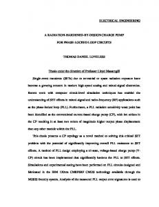
B) Hamming Code Technique in the registers Hamming code [7] is an error-detecting and errorcorrecting binary code that can detect all single and double-bit errors and correct all single-bit errors on an n-bit word. A Hamming code satisfies the equation 2m >= n +1, where n is the total number of bits in the protected data and m is the number of check bits in the data. This coding method is recommended for systems with low probabilities of multiple errors in a single data structure (e.g., only a single bit error in a byte of data). For example, for an 8-bit data, it is necessary 4 check bits resulting in a new 12-bit data. Figure 2 presents the main structure used to protect the registers. The 12-bit register in the new design replaces the original 8-bit register.
D5
8-bit data
Hamming Codification, check bits generator 12-bit data
Hamming Decodification, 1-bit error correction
Figure 2 – Hamming Code Technique
effects of a bit flip in this register can be very hazardous for the system. The finite state machine (FSM) of 8051 has 24 states, which have been represented by a 5-bit register to form the next state of the machine. This register must be protected by Hamming code to avoid errors under radiation. This technique uses six packages functions, one called coded with 1-, 2- and 5-bits input and 3-, 4- and 9-bits output, and other called decoded with 3-, 4- and 9-bits inputs and 1-, 2- and 5-bits outputs. Its structure shown in figure 3 is similar to the packages previously described.
III. The SEU hardened 8051 micro-controller Four structures in the 8051 VHDL description have been protected by Hamming Code: the Finite State Machine, the RAM memory, the Control unit and the Datapath. These blocks contain memory cells that can be affected by SEU radiation effects. The Instruction unit is a completely combinational structure and in principle it is not subject to bit flips, making no necessaries protection schemes for it. The ROM block is also immune to these faults, since its content can not be modified. VHDL simulations have been used to check the correct Hamming code implementation. In order to implement the Hamming code, eight combinational components were described in VHDL and used as a package in the 8051 VHDL description. The first component receives an 8-bit data and returns a 12-bit coded word. The second component receives a 12-bit word and returns an 8-bit decoded and corrected data. And consequently for the 1-, 2- and 5-bit registers, returning 3-, 4- and 9-bit respectively. The size of each Hamming code/decode block grows proportional to the increase of the protected data bits. Table 2 represents the sensitive area percentage of each micro-controller unit. The internal memory is the most susceptible area for errors because it represents 88% of the total microprocessor sensitive area. However an error in the other units can represent also a significant problem for the system resulting in data errors and lost of sequence. Table 2 – Sensitive Area Percentage of the 8051 microcontroller 8051 unit # latches 8051 sensitive area Control Unit 11 1.2 % State Machine 15 1.3 % Datapath Unit 104 9.5 % Internal Memory 1024 88.0 % Total 1154 100.0 %
code Protected register
decode Figure 3 – Hardened registers scheme from the control unit and state machine In the new FSM, the next state is coded before being stored, and decoded before being used in the control unit. In case of occurrence of a transient fault, the error is corrected. Since coding and decoding operations are completely combinational, there is no difference in terms of machine cycles needed for an operation.
B) Transient Fault Detection and Correction in SRAM memory Instances of code blocks with 8-bit input and 12-bit output and decode blocks with 12-bit input and 8-bit output were used to detect and correct transient faults in the SRAM 8051 memory. In the memory access protection, all data words are coded before being stored in the RAM memory, and all memory words are decoded (and possibly corrected) before being used in an operation. Figure 4 presents this structure.
data
RAM
code decode
address
Figure 4 – SRAM memory protected scheme
A) Transient Fault Detection and Correction in Finite State Machine and Control unit
C) Transient Fault Detection and Correction in Datapath
The Finite Sate Machine (FSM) and the Control unit represent together only 3% of the sensitive area of the 8051 micro-controller. Although the register sensitive area in these units is much smaller than the internal RAM memory, the
The Datapath is composed of many registers, multiplexors, glue logic and an Arithmetic Logic Unit (ULA) that are enabled according to the signals from the Instruction unit. The clock synchronizes all the registers. The main basic structure is composed of a multiplexor and a register.
LIMA
D5
The same component models for coding and decoding used in the memory were also used to protect the registers in the datapath. There are two version of the Datapath, in the first one, two registers have been protected, the accumulator and the program counter. In the second one, all the registers are protected. Figure 5 shows the structure used to protect the registers.
code
Program Counter, Instruction registers, and in general, all the memory element (datapath registers, control part flipflops,…). PC
RS232
8051 ROM
decode
RAM
B U F F E R
B U F F E R
Power Supply
DUT
Glue Logic 5V
MMI
Figure 5 – Hardened Datapath registers scheme Mother Board
IV. Prototyping the Fault Tolerant 8051-like Microcontroller A board implementation has been done with the robust 8051. The hardened description was prototyped into three programmable logic devices customizable by EEPROM technology. This board is being verified using a dedicated tester to analyze the capabilities of this technique.
A) Radiation Ground Testing The radiation ground test consists in exposing the SEU hardened 8051 board, while it carries out a given activity, to an appropriate particle beam. Such on-line testing needs: a particle beam, a test methodology, defining the activity of the device under test (DUT) and an electronic test equipment for controlling and observing the behavior of the DUT during its exposition to radiation. The particle beam can be obtained by Radiation Facilities such as particle accelerators: cyclotron, linear accelerators and synchrotron equipment based on fission decay sources such as Cf252. The THESIC [8] system (Testbed for Harsh Environment Studies on Integrated Circuits) developed at TIMA is a flexible and general circuit qualification platform that takes into account the random nature of SEUs occurrence, both in time and affected memory cell. The capabilities of THESIC tester were widely proved during lastly performed test campaigns, which aimed at the evaluation of the operation under radiation of various microprocessors. During the radiation ground test, the THESIC motherboard is fixed to a moving stage support allowing performing the alignment DUT-beam. It communicates to an external PC through a serial link connection. During a radiation test, target DUTs (Design Under Test) included on a daughter board are successively aligned with the beam. The DUT is the hardened 8051 board. Figure 6 illustrates the THESIC schematic. The SEUhardened 8051 prototyped board is a daughter board of Thesic and it will be tested under this platform. The main targets for upset errors of 8051 processor are: the 128 bytes internal RAM, the Special Function Registers, the
LIMA
Daugther Board
Figure 6 – THESIC Schematic
B) SEU-Hardened 8051 daughter board The use of presently available high-density programmable circuits such as Field Programmable Gate Arrays (FPGAs) and Programmable Logic Devices (PLDs) is an attractive approach to fast prototyping and reducing cost. There are several ways to customize these chips: using SRAM, antifuse or EEPROM technology. Field Programmable Gate Arrays (FPGAs) based on SRAM technology are largely used to prototype digital systems due to their high-density, performance and fast turnaround time. However, SRAM elements are strongly sensitive to SEU. In other words, to implement a version of a transient errors protected micro-controller in a FPGA based on SRAM, it is necessary not only to design a robust microprocessor, but even to use some SEU mitigate solutions. These mitigate solutions can be TMR (Triple Modular Redundancy) or other techniques inside the programming bits of the chip. Aiming at avoiding the radiation effects in the 8051 prototype, such as bit flips in the chip customization, programmable logic devices (PLDs) customizable by EEPROM were used. PLDs customizable by EEPROM have been chosen to implement the first prototype of the fault tolerant 8051 micro-controller, since these memories are known to be insensitive to radiation). In such way, device customization has less chance to be affected by the radiation environment and the fault tolerant 8051 implementation can be tested by itself. The fault tolerant 8051 was implemented in an Altera PLD [9], family MAX 9000. This version of the 8051 uses three chips, one EPM9560 with 208 pins and two EPM9400 with 84 pins. The EPM9400 has 580 flip-flops and 25 Logic Array Blocks (LABs) composed of 400 complex logic cells (CLBs) in total. The EPM9560 has 560 complex logic cells (CLBs). The macrocell consists of three functional blocks: the product terms, the products select matrix and the programmable register. The macrocell can be individually configured for both
D5
sequential and combinational operation. The combinational logic is implemented in the local array, which provides five product terms per macrocell. A board composed of the PLDs, the RAM and ROM memories and a logic interface was built. It is presented in figure 7. The internal memory was implemented outside the PLDs. Four chips are going to be irradiated, the PLD running the Datapath, the PLD running the Control and State Machine and the two 8-bit memory chips. This board is going to be tested in the THESIC tester environment [8] under radiation ground test in I.N.P, Orsay, France. It will be tested under the particle accelerator TANDEM Van de Graaff with heavy ions.
V. Overhead Area results There were developed six versions of the protected 8051 micro-controller in VHDL description with an 8-bit and 16-bit program counter (PC). These versions are the standard 8051 protected in the internal memory, in the control unit and in the state machine, the version with the program counter and accumulator protected too and the full-protected version. The area overhead of each hardened 8051 unit is presented in table 3. It presents the increase of sensitive area in number of latches, the number of code and decode blocks for each protected group of latches and the number of complex logic cells necessary in the PLD to implement the code and decode logic blocks. Analyzing the table, the internal memory represents the most efficiency structure to be protected by Hamming Code because although the sensitive area increases in 50% such as in
the Datapath unit, it is necessary only one code and one decode logic block. The datapath is the most costly structure protected by Hamming Code because of the high number of code and decode logic blocks used to the protection. Table 3 – Overhead Area Results # CLBs to Sensitive #code and the code / Area decode SEU-Hardened decode Overhead (%) logic blocks blocks Control unit 72 06 36 State Machine 80 06 42 Internal memory 50 02 44 Datapath I 50 26 186 Datapath II 50 10 70 Previous results [3] performed by fault injection in the THESIC platform [10] show that the standard 8051 microcontroller from Intel with the supposed internal memory protected has 98% of reliability. More than 12000 errors were injected randomly in the microprocessor. Only 2% of the amount of errors injected in the microprocessor have resulted in errors or lost of sequence. This experiment has also analyzed the errors in the special function registers (SFR). In this case, 69.7% that occur in the registers are tolerated, 10.7% have resulted in errors and 19.6 have resulted in lost of sequence. Table 4 shows the results of the robust 8051 prototyped into the PLD MAX9000 family.
Daughter board
Instruction unit
Datapath
Control + FSM
Internal Memory
DUTs THESIC Mother board
Figure 7 – SEU Hardened 8051 board and THESIC mother board
LIMA
D5
Table 4 – Results of robust 8051-like Micro-Controller implemented in Programmable Logic Devices from Altera Version Control unit State Machine Internal memory Datapath #flip-flops1 #CLBs 8051- 8bit PC Not protected Not protected Not protected Not protected 130 536 8051-8bit PC Full protected Full protected Full protected Not protected 150 692 8051-8bit PC Full protected Full protected Full protected Partial protected2 158 824 8051-8bit PC Full protected Full protected Full protected Full protected 202 909 8051-16bit PC Not protected Not protected Not protected Not protected 138 579 8051-16bit PC Full protected Full protected Full protected Not protected 158 728 8051-16bit PC Full protected Full protected Full protected Partial protected2 170 909 8051-16bit PC Full protected Full protected Full protected Full protected 214 987 1 Number of flip-flops in the microprocessor (control unit, finite state machine and datapath). The internal memory is implemented outside the PLDs like it is shown in the board photo. 2 The datapath is partial protected because only the accumulator and the program counter registers were protected by Hamming code. The full-protected versions of the 8051 do not fit in the PLDs family due to the reduced number of CLBs in the MAX9000 family. The Hamming code protection technique against SEU is very efficiency in terms of area overhead. The full-protected 8051 version is around 70% bigger in terms of CLBs and it has used 55% more latches in the PLDs. Comparing to other techniques such as Triple Modular Redundancy (TMR), the Hamming code has at least two advantages: smaller area overhead (less than the double) and not only error detection but also error correction features.
VI. Conclusion and future works This paper has presented the prototype of a fault tolerant 8051-like micro-controller for space applications. A particular consequence of radiation environment, the Single Event Upsets phenomenon, was tackled by the insertion of error correcting codes in an existing VHDL design of this microprocessor, which is widely used in space projects. This robust processor was implemented in a programmable logic device customizable by EEPROM technology. The effectiveness of the proposed strategy will be evaluated under radiation ground test and also by software fault injection experiments, performed by means of a dedicated system developed at TIMA laboratory. This tester, called THESIC, is a compact and flexible well suited tool for performing most of qualification tests (radiation, temperature, EMC) for complex integrated circuits. Testing the SEU hardened version of the 8051 in the THESIC fault injection capabilities allows us analyze the behavior, with respect to transient bit flips, of architecture built around the micro-controller. Thousand of bit flips are going to be injected in parallel of the execution of a test program. Preliminary results allow to predict that an 8051 robust version based on the hardening of internal RAM, datapath and finite machine registers by an error detection and correction strategy, will tolerate in 100% of the cases the effects of transient bit flips. The first results in area shows that the SEU immune 8051 micro-controller uses less then
LIMA
the double of the area of the not protected microprocessor if a PLD is used for the implementation.
References [1] MA, T.; DRESSENDORFER, P. Ionizing Radiation Effects in MOS Devices and Circuits, Wiley Eds, New York, 1989. [2] NORMAND, E. Single Event Upsets at Ground level. In: IEEE Transactions on Nuclear Science, vol. 43, no. 6, Dec, 1996. [3] COTA, E.; CARRO, L.; LUBASZEWSKI, M.; VELAZCO, R.; REZGUI, S. Synthesis of 8051-like Microcontroller Tolerant to Transient Faults. In: 1st IEEE Latin America Test Workshop (LATW), Brazil, 2000. [4] Embedded Micro-controllers, Intel Datasheet, 1994. [5] CARRO, L.; PEREIRA, G.; SUZIN, A. Prototyping and Reengineering of Microcontroller-Based Systems. In: IEEE Rapid Systems Prototyping Workshop. Proceedings… June 1996. [6] SILVA, L.; LIMA, F.; CARRO, L.; REIS, R. Synthesis of the FPGA Version of 8051, UFRGS Microelectronics Seminar (12), June 6-7 : Porto Alegre, BRAZIL, pp. 115-120, 1997. [7] KOHAVI, Z. Switching and Finite Automata Theory, McGraw-Hill, 1970. [8] VELAZCO, R; REZGUI, S.; CHEYNET, Ph.; BOFILL, A.; ECOFFET, R. THESIC: A testbed suitable for the qualification of integrated circuits devoted to operate in harsh environment, IEEE European Test Workshop (ETW’98) pp. 89-90, 27-29 Mai 1998, Spain. [9] ALTERA Data Book 1999. Altera Corporation, www.altera.com, April, 2000. [10] VELAZCO, R.; REZGUI, S.; ECOFFET, R. Transient bitflip injection on microprocessor-based digital architectures, presented at Nuclear and Space Radiation Effects Conference, NSREC 2000 , (Reno, USA, 24-29 July 2000).
D5