These environments are e ective for building desirable behaviors of autonomous robots. The desired behav- ior of a \ballboy robot" was actualized by designing.
Designing Asynchronous Parallel Process Networks for Desirable Autonomous Robot Behaviors T. Oka *, K. Takeda, M. Inaba and H. Inoue * Graduate School of Information Systems Univ. of Electro-Communications Tokyo, Japan 183 Abstract
The behavior of an autonomous robot is generated by the dynamics of the interaction between the brain and the environment. The designer of the brain must describe and actualize a system that makes a desirable interaction with the contingent physical world in real time. In this paper, we propose a computational model for describing the brains of autonomous robots and an approach to integrating functions of autonomous robots. BeNet, our model, is a network of asynchronously communicating processes that change their state and output vectors in their own frequencies determined by the designer. One can describe a modular system for a desirable behavior as a BeNet that interacts with the real world in real time. We design modules of a BeNet that calculate a part of the internal representation of the brain that is necessary for the desired behavior. The portions of internal representation such as action command, attention command, perceptual/sensational information are realized as messages among the modules. Building such a modular system helps you to develop a brain for a desirable behavior, modifying and extending the described system, since the ow of information and the roles of the modules are clear. We have implemented environments for developing a BeNet on parallel computers. In these environments, you can describe BeNets that consist of processes of wide range in complexity and frequency of calculation, and test their behavior in the real world immediately. These environments are e�ective for building desirable behaviors of autonomous robots. The desired behavior of a \ballboy robot" was actualized by designing a BeNet in our environment, based on our approach. The subsystems for vision, motion and decision, and the integrated BeNet are presented. 1
Introduction
The brain of an autonomous robot is a system that sends motion signals to the motors of the body acquiring information about the external world through sensors. To behave in the dynamic real world, the system should make a stable interaction with the environment, changing its internal state reactively. In the eld of motion control, perception and decision making, it is widely accepted that the robot should
Dept. of Mechano-Informatics Univ. of Tokyo Tokyo, Japan 113
be reactive enough to interact well with the world through sensors and motors. For example, a reactive system that selects the action directly from the situation is more robust than a system that searches for a path from the current situation to the goal[1][2]. A tight sensory-motor coupling enables skilled and robust motions[5][7]. Feedback signals with short delay time are necessary to generate a motion for active perception in many cases. In this paper, we propose to describe the brain of an autonomous robot as a network of asynchronous parallel processes, which is called a BeNet. The designer of BeNets describes the rules and the frequencies for changing the states of the processes, and connects the input and output of the processes. The designer can describe a modular system that interacts reactively with the physical world in real time as a BeNet. In our approach, we determine the internal representaion of the brain, and design modules that calculate important information for the robot behavior, such as perceptual information, action command, attention command and so forth. The brain will consist of subsystems for perception/sensation, motion, and decision system. The structure of the brain is determined by the designer so that the robot behaves desirably. A system described in such a way is easier to modify or extend, since the role of each module is clear to the designer. We have developed environments (BNRB's) for developing the brains of robots by programing BeNets and testing their behaviors. The developer can describe the rules of the modules in generic programming languages such as C. The programs are compiled and linked to generate a code that is executable by a large scaled parallel computer system. This makes it possible to describe a desirable brain, test it and modify or extend it in a short term. We show how to design the vision, motion and decision system of autonomous ballboy robot and integrate them based on our model and our approach. The robot can search for a ball, follow and catch it, carry it and throw it to a goal autonomously.
2
BeNet and Our Approach to Integration
2.1
sensory input
Describing Autonomous Behaviors
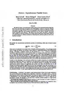
The nervous system in the human brain is a good example of reactive systems materialized with physical apparatus. It shows that intelligent autonomous behaviors are generated by asynchronous parallel systems. The human brain is reactive as each neuron in a human brain changes the state and the output asynchronously with the other neurons. However, designing such a massively parallel system that consists of simple processing units for a desirable autonomous robot behavior is not a trivial easy task. The designer needs a more e�cient way to describe reactive systems that interacts correctly with the world. A system that interacts with the environment is described by the following simple expressions. o(t + �t) = f (i(t); s(t)) (1) s(t + �t) = g (i(t); s(t)) (2) Three vectors o(t); s(t); i(t) represent the output, the internal state, and the input of the system, respectively. �t is the temporal parameter that determines the frequency of calculation of functions f and g. These expressions precisely determine the behavior of the system interacting with the external environment. The designer of an autonomous robot should describe something equivalent to the above expressions. o(t) and i(t) represent the motor commands and sesory data. s(t) is the representation of internal state of the brain. In order to design a desirable behavior of the robot, the expression of s(t), as well as f , g and �t is important. The value of each element of o(t) and s(t) will not always change at every time step. The value will not always depend on every element of the vectors i(t 0 �t) and s(t 0 �t). Therefore, the vectors o(t) and s(t) can be divided into many groups that have their own input vectors(subsets of i(t 0 �t) and s(t 0 �t)) and their own frequencies of calculation. Calculating these groups in parallel is more e�cient than calculating all the elements at every time step sequentially. The values of some elements of s(t) may be referred only for the calculation of the groups that the elements belong. These elements are internal state variables of the group. In the following subsection, we de ne a model for designing the brain, which is consisted of parallel processes that calculate such a group asynchronously. We call the model BeNet(a short form of Behavior Network). Each process receives the input and changes the state and the output periodically. The frequency of calclulation, the number of input and output messages, the complexity of the program and the size of memory of each process are determined by the designer. There are no constraint for describing such a system, if the designer has a language to describe the behavior of each process and the network con guration. This model helps the developer to design a modular system that interacts with the physical world, since the description of the system contains temporal parameters, i.e., frequencies of the processes.
BU i(t)
I(t)
internal state
S(t)
s’(t)
Real World
motor output
F,G t
O(t)
o(t)
uni-directional message
BU
BU
BU
BU
sensory input motor output
Figure 1: BU and BeNet 2.2
the BeNet Model
A BeNet is a network of Behavior Units(BU's) that change the output and the state asynchronously. A BU has an input message vector I (t), an output message vector O(t) and a state variable vector S(t). The ith element of S (t) and O(t) are calculated by the following expressions. Si (t + 1t) = Fi (I (t); S (t)) (3) Oi (t + 1t) = Gi (I (t); S (t)) (4) The designer chooses the sizes of the vectors and the temporal parameter 1 t, programs the functions Fi and Gi for each BU and connects the BU's to con gure the BeNet. There are units that have input from the sensors or output to the motors of the robot. You may describe the whole brain as a large and complex BU since the model of BU has no limitation in complexity. However, in practice, it is better to design a parallel system, because it will take long time to calculate many state variables and output signals to the motors. In addition, a parallel modular system is easier for the designer to describe, modify, or extend. 2.3 Approach to Integration It is important for the designer to de ne the meaning of each message in the BeNet and hide most of internal state variables inside the modules(BU's) to make the roles of BU's and the structure of the system clear. If the descirbed system does not behave like the designer desires, the designer checks if all messages are calculated correctly, and discover the problem. In many cases, the problem will be solved by modifying a BU that outputs a wrong message, if the roles of BU's are clear to the designer.
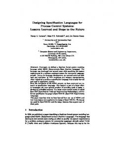
In Brooks's Subsumption Approach, the designer creates a system, tests it in the real world and adds a new layer to extend the repertoire of the robot behavior[3]. This method has a di�culty when the system becomes complex and the designer wants the robot to do complex tasks. The processes of perception, motion generation and decision making are not clear for even the designer. For this reason, it is di�cult to modify the system or add new functions. In our approach, the designer determines the internal representaion of the brain for the desired behavior. The robot should distinguish many di�erent situations and make proper actions. The desired behavior of the robot determines signi cant elements of the vector s(t), the internal representaion. The designer describes a BeNet that consists of BU's for calculating elements of s(t) and o(t). Each BU is designed so that it behaves desirably, interacting with the external system. Designing a BeNet, you do not have to synthesize a desirable behavior by combining simple modules. As calculation of s(t) and o(t) is classi ed into perception, decision making and motion generation, a robot brain will have three subsystems. The functions of perception, motion generation and decision making are generated by the dynamics of the interactions among the subsystems and the physical wolrd(Fig.2). In the system described in our approach, the three processes are designed separately and the ow of data is much clearer than the Subsumption Approach. Note that indispensable information such as perceptual information, action commands are represented as messages between two subsystems. Most of the other information will be hidden inside the modules. context
3.2
c(t)
subsystem Decision p(t)
ac(t)
perceptual
at(t)
action, motion
attention Perception sensational
Sensation
Motion
se(t) i(t)
o(t)
sensory input
motor output
Real World
Figure 2: interactions among the subsystems 3
Environments for
Developing Au-
tonomous Brains 3.1
only for the whole system but also for modules of the system. It is essential that the designer can describe the system e�ciently using appropriate languages and verify the described system immediately in the real world. Brooks's Behavior Language(BL) is a language to describe reactive systems[4]. His group developed an environment in which the designer writes a program in BL and compiles it to build a brain hardware. The designer of the system describes behaviors in BL and each behavior is compiled to generate an asynchronous network of Augmented Finite State Machines(AFSM's). As the language is a subset of Common Lisp, the designer can develop each function of behavior in any programming environments for Common Lisp with a interpreter. However, in this environment there is a limitation in the variety of behaviors that can be actualized in the physical world, because the behavior functions are to be calculated by a digital circuit limited in size and structure. The designer may not always choose a function, numbers of input, state variables and output, and a frequency of calculation that are appropriate for a module. This limitation in description is a great disadvantage in designing a desirable behavior of a robot. We developed enviornments for describing BeNets in programming languages and actualize them on parallel computers. These environments allow the designer to develop desirable brains more e�cinetly by describing a variety of BeNets and verifying them on parallel computers. One can program a BeNet by describing the frequencies and the functions for BU's and the network con guration. The described BeNet program is compiled and simulated e�ciently.
Environments for Developing
In developing a robot brain, it is necessary to verify the behavior of the described system and modify it many times. This process should be repeated not
BeNet for Robot Brain
We have implemented environments for programming BeNets, in which the designer of the brain can program the behavior of each process in C or C++ and the con guration of the BeNet. We call such an environment BNRB(BeNet for Robot Brain). For the time being, there are two environments: BNRB/tp(for Transputers) and BNRB/mt(for Sparcs). In BNRB/tp, you can program a BeNet on a Transputer network for controlling a robot body. The frequency of calculation for each BU is controlled in real time using the timer of the Transputer on which the process runs. Since usually more than one BU are simulated on a Transputer, processes are scheduled for time sliced execution. Our group has developed Transputer boards with vision and sensory input[8], boards with a parallel I/O for motor control and wireless system that enables to control a remote body from Transputer networks[9]. In BNRB/tp, the designer can program a module that interact reactively with the external system and con gure a network of such modules. The designer describes two function in C for each BU. One is for initializing the state variables, and the other is for changing the state and the output periodically (by Fi and Gi ). The network con guration is written in the con guration language for Transputers. These programs are compiled and linked with the system programs, to
create a program that is bootable and executable on a Transputer network. 4
Designing
the
Brain
of
an
Au-
tonomous Ballboy Robot
In this section and the following sections, we show how the brain of an autonomous robot is designed as a BeNet based on our approach. In this paper, we describe an example of a ballboy robot that prowls on the oor searching for a ball, follows and catches a ball, carries it and throws it to a goal. The robot repeats this sequence autonomously, avoiding obstacles. 4.1 the Ballboy Robots We have developed two 4-legged mobile robots with a hand for grasping objects, and a camera. Ballboy-I has no extra sensors, 16 DOF and its 2 DOF hand on the top of its head mounted on the 2 DOF neck. It has 4 free wheels on the bottom and can walk without balancing. The length of the body is approximately 20cm. Ballboy-II is a larger 24 DOF robot that has a 3 DOF arm with a wrist and a hand on it, and tactile sensors on the legs and the hand. All the motors are remote-controlled by a wireless system and the image of the camera is transmitted through a wireless video link. 4.2 Designing the Brain On the rst stage, the designer lists up actions, perceptual information, contexts for action selection, and rules for decision of action and contexts that are indispensable for the robot's desirable behavior. In the case of the ballboy robot, the robot needs to make actions like following a ball or a goal, catching and throwing a ball, searching for a ball or a goal and so on. The robot also needs to percept the distance from the target or an obstacle, the size of the ball, the direction of the target or obstacles etc. The brain system of the robot must contain a representation of the state of the behavior, because the robot has to distinguish the state that cannot be derived only from the sensory input. Thus, important elements of the internal representaion s(t) are determined. On the second stage of designing, the subsystems of perception, motion generation, and action selection are materialized in detail. BU's that calculate elements of s(t) determined on the rst stage are designed. The sensational information for action generation and attention commands for the vision system (the rest of signi cant elements of s(t)) are de ned on this stage. At this point, it is clear what kinds of messages are passed among the subsystems. The messages belong to the most important elements of the internal representation of the robot brain. The behavior of the robot is generated as the subsystem and the environment interact with each other. In the following sections, we describe how we build the subsystems for the ballboy behavior. 5
Vision System
The purpose of the vision system is to nd the target object, track it, recognize it, distinguish obstacles and free space, and detect danger. We designed the vision system based on BeNet that can nd and
track the target object autonomously using top-down and bottom-up information. This vision system is designed inspired by psychological models of human attention selection[10][11]. The vision system contains peripheral feature extractors, foveal feature extractors, and attention control units. The peripheral units extract feature distributions that are useful not only for determining the area of attention but for extracting global visual information. The foveal units extract features of the area of attention to recognize the object in the area. 5.1
Creating Global Feature Maps
5.2
Finding Balls and Goals
5.3
Tracking the target
We use some global feature maps in order to nd the target or obstacles in the scene. To extract areas of white balls, white marks or shadows on the oor, the map of intensity is useful. The peripheral vision system creates coarse maps of white objects and shadows from the available intensity map(512 2 512 pixels). The system also creates a map of the oor area in the whole image plane. This map is also calculated from the intensity map. We assume that the oor area in the plane always contains a small area near the bottom. The histogram of this small area represents the distribution of P (I (x; y) = I jf loor(x; y)), the probability that a point in the oor has an intensity I . The distribution P (I (x; y) = I ), the probability that the intensity of a point in the image plane will be I , is also available from the intensity map. The probability that a point (x,y) in the image plane with the intensity I , belongs to the oor area is P (f loor(x; y)jI (x; y) = I ). The map of oor is created using the relation derived from Bayesian Theorem, P (I (x; y ) = I jf loor(x; y))P (f loor(x; y )) Pf (x; y; I ) = P (I (x; y) = I ) (5) Using the histogram of current image, the behavior of area extraction is adaptive. This method is also applied to area extraction using the color map of the image plane, if it is available. When the robot is searching for a ball, the vision system receives a top-down command to nd a white circle. The peripheral vision system labels areas on the white map and send the position and the size of a labeled area to the attention control units if the shape is round and the size is large enough. Searching for the goal, the vision system receives a command to nd a white rectangle. In this case, the peripheral system send the position and the size of a area, if it is a rectangle. The candidate area of attention extracted by the peripheral units is tested by the foveal units. If the area is likely to contain the target, a ball or a goal, the vision system start tracking the object. It creates a template image for tracking segmented from the candidate area. The target is tracked by template matching based on the cross-correlation between the searching area of the current image and the template image. The
searching area is set around the position of the object in the frame a cycle before. The size of the object is also tracked by matching reduced or extended image of the template. Because the cross-correlation values are calculated by a hardware on a Transputer vision board, the system can track the target in real time. While the system is tracking the target object, the foveal units continue extracting features from the area of attention. Brightness, shape and contrast are used for con rming that the system is tracking the object successfully. If the system fails to track the target, it starts searching for a new object in the scene. 5.4 the other information from vision The feature maps calculated by the peripheral units are useful for extracting other important information. For example, if the robot happens to go under the desk, the average level of the intensity becomes extremely lower. This helps the robot to go backward and turn to the free space. The area of the oor helps to navigate the robot safely. This sensational information is used by an action generator called wander in the motion system described in the next section. 5.5 Network of the Vision System The network of the vision system is shown in Fig.3. The units white and oor extract candidate areas for attention and other information. Attention determines the area to examine based on the given features of the target. Track segments the template image and track the target. Bright and outline extract features of the foveated area and send them to phase. Phase decides whether track tracks the area of attention or examines another candidate from attention. unit with visual input
unit
area candidates
white floor
track attention
bright s
outline phase
features shadows brightness free space
positon, size target object features of target
phase of attention
Figure 3: The network of the vision system 6
Motion System
The motion system receives action commands from the decision system and generates a time series motion pattern monitoring sensational information. Modeling the motion system as a BeNet has some advantages. A BU with sensational information and motion command as input and with command to some motors as output, will generate a motion pattern interacting with the environment and the other BU's of the brain. Designing a BeNet, the designer can program modules
with senosry feedback that reactively generates desirable motions in parallel. Complex motions for making some action will be realized by combining premitive motion patterns, describing a hierarchical motion system like the human motion system. For the ballboy robot, we designed a hierarchical motion system that can generate actions for the desired behavior. Each BU change its state and output every 25:6msec, monitoring sensory and command input. Every BU is described in a small code of C. 6.1 Pattern Generators A unit on the pattern level of the motion system generates a primitive and useful motion pattern like walking, turning or grasping. It receives sensory input and control input, and sends motion pattern in every cycle. The brain of ballboy robot includes 8 pattern generators. They are stand, walk, turn, gaze, look around, grip, grab, and climb. They receive some parameters as control input for the motion they generate. For example, walk generate a walking pattern receiving speed (between -10 and 10) and steering (between -5 to 5) in every cycle. This makes the robot possible to move toward various directions at various speeds. The other pattern generators also receive control input. 6.2 Action Generators A unit on the action level generates an action sending control signals to the BU's on the pattern level that actually generate motion patterns for the action. The brain of the ballboy robot has 9 action generators. They are follow, avoid, gaze at, look for, search, wander, catch, release and stop. Follow controls the speed and steering of walk based on the target direction, enabling gaze to work. Wander sends signals to walk, turn and stop, and leads the robot where it can proceed. Each unit on the action level receives action command from the decision system. Only the BU's corresponidng to the command send output signals to the pattern level. 6.3 Network of the Motion System The network of the motion system is shown in Fig.4. The output of the pattern generators, e.g. look ar, is connected to the units like neck that determines the angles of the neck. The action generators, e.g. look for, send messages to the pattern generators that actually generate motions for the actions. The network is e�ciently described because it changes the state reactively and generates motions as the dynamics of the interaction with the external system. An action is described as a temporal and spacial combination of primitive patterns. This hierachical structure diminishes the costs for both describing and processing. Extending such a system is not di�cult. 7
Decision System
The decision system sends commands of action and attention based on the context and the perceptual information. It changes the context at every time step, a�ected by the perceptual information from the perception system. Thus, the behavior of the robot is generated by the dynamics of the decision system which has external input from the perception system.
target position s
look_for gaze_at
look_ar
s s
search s
hand
turn back
release
s
catch
action s
avoid
free space
neck
s
Otherwise it will be the ball. The network of action transition is shown in Fig.5. An arrow between two actions means that one action may be selected when the other is being executed. One of the arrows from the current action is selected based on other context and perceptual information from the vision system.
stand
release
follow
gaze
grab
stop catch
s
actuator
angles action
s
grip
s
search
s
turn
s
wander
gaze at
motors
s
Action Level
look for
s
walk
s
follow
leg
action transition
Pattern Level
Rules for the Context
7.2
Rules for the Action
The best action to make changes as the situation changes. As the situation is not derived only from the direct sensory input, the decision system keeps the context information and updates it. For the ballboy behavior, the current target and the current action are necessary. The designer de nes the context variables as the internal representaion of the situation. The context variables of the ballboy are as follows: 1. the target 2. current action 3. whether the target is found or not 4. how long the action has been selected The context of the behavior changes while the robot continues making actions. For example, if the robot successfully catches the ball, the target will be the goal instead of the ball that has been the target. If the robot tries to catch the ball and fails, the target will be still the ball. This context transition is described as a rule: \If the target is a ball, the action is catch, the robot has succeeded to catch a ball, and the robot has a ball in its hand, then the target is set to be a goal." It is clear that the condition of the rule includes both the context and perceptual information. We programmed such rules for changing the context. The action of the current cycle is decided on the action selected a cycle before and the other items of the context. We programmed the action transition rules so that the robot behaves desirably. For example, if the current action is gaze at and the ball is close enough to catch, the next action will be catch. The action catch lasts until the motion is completed. The next action after catch will be search. The target will be the goal, if the action catch has succeeded.
avoid
Figure 5: The network of action transition
Figure 4: The network of the motion system 7.1
wander
8
Integrated Network
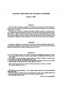
The network designed for the ballboy behavior is shown in Fig.6. The network is simulated by a dozen Transputers including 8 Transputers with image frame memory and a Transputer with a motor control port. The BU called a select is the decision system of the brain. The vision system consists of the units above a select. The other units belong to the motion system. The vision system looks for the target object determined by the decision system. While the vision system is tracking the target, its position and size are always sent to the decision system and gaze in the motion system. The decision system periodically sends an action command to all the action generators in the motion system. The behavior of the system in each situation is easy to understand, as the ow of information is clear. The integrated system behaves like the designer intended. Each action is made successfully using visual information. Each unit is programmed to change the state in no more than 33msec so that the robot is reactive whatever action it is executing. The decision system changes the context, the action and the topdown signals to the vision system in every 25:6msec. This makes it possible to utilize the latest perceptual information for selecting the action. The context information is also important for the desirable behavior. In Fig.7 and 8, an action sequence of the ballboy robot is shown. The robot nds a ball, follows it, catches it, turns back, nds a goal, approaches to it and throws the ball to it. After the robot throws the ball, it searches for another ball. This sequence can be traced on the transition network shown in Fig.5: search ! look for ! gaze at ! follow ! gaze at ! catch ! turn back ! look for ! search ! look for ! gaze at ! follow ! gaze at ! release. If the robot fails to catch the ball, judge will let a select notice that, and the robot will try to nd the ball again, while the target, a ball, will not change.
vision white floor space
track
x,y,size
bright
attention
s track/find
target
outline
find x,y,size
descision ?success s
look_for
look_ar
s
gaze_at
s
search
neck
s
grab
stop catch
gaze
s
s
hand
stand
motion
s
release
s
avoid follow wander
actuator
a_select
judge
s
grip
s
s
turn
s
s s
walk
s
leg
Figure 6: the BeNet for the Ballboy If the robot stacks with some obstacle, the direction and the distance of the target changes in an unexpected manner. This allows the decision system to select avoid and the robot to go backward and turn to the target again. The decision system selects the action based on both the status of the external world and the internal motivation. Selecting the action reactively, the robot behaves desirably in the dynamic environment. 9
Discussion
Designing the brain of the robot as a BeNet, one can describe any module that interacts with the external system and con gure a network of such modules. The designed network for the ballboy robot is reactive as the whole and robust in the dynamic environment. The robot can recognize the situation from the sensory input and move quickly. The robot can follow the target because new visual feedback messages from track are available from gaze in 33msec. The network consists of modules that actualize the functions of perception, motion and decision. The vision modules are designed to extract information necessary for motion, e.g. the position of the target for following and action selection, e.g. if the robot can follow the target. Because we designed the system as a BeNet, we could exibly determine the function of each module and the network con guration. In our approach, it is easier to accomplish a coherent behavior than the Subsumption approach because
the system consists of functional modules that calculate elements of s(t) de ned by the designer and o(t), motor commands. The designer can program the decision system on an abstract level. It is not di�cult to extend the repertoire of the robot by re-programming the decision system or by adding a new unit for another function. The internal representaion and the structure of the BeNet are designed so that the robot behaves like the designer desires. The messages among the three subsystems and the context variables of the decision system are the most signi cant elements of s(t). BNRB/tp makes it possible to verify a variety of BeNets in the real world and modify them in a short term. This accelerates developing desirable autonomous robots. 10
Conclusion
In this paper, we proposed to design the brain of an autonomous robot as a BeNet, a network of asynchronous processes that change their state and output in their own frequencies determined by the designer. As a BU interacts in real time with the external system including physical world through messages, BeNet is a good model for describing a modular brain of an autonomous robot. By giving semantics to each message and internal state variable, the designer de nes the internal representaition of the robot brain, so that the robot behaves desirably. The brain is described as a network of parallel modules of which roles are clear. In our approach, the brain has three subsystems for perception, motion and decision making. The susbsystems interact with each other to calculate important elements of s(t) and the behavior of the robot is generated as the brain interacts with the environment. We developed environments in which the designer can program a BeNet that runs on Transputers or Sparcs. In BNRB/tp, you can immediately verify a described BeNet on a Transputer network in real time and control a real robot. This makes it possible to develop the brain of autonomous robot e�ciently. We described how to design a brain of a ballboy robot as a BeNet based on our approach. The described BeNet consists of many functional modules of which roles are clear so that it is easy to modify or extend, although the whole system is rather complex. The BeNet is tested in BNRB/tp and the robot showed a desirable behavior. References
[1] P.E.Agre and D.Chapman, \Pengi:An Implementation of a Theory of Acticity" Proc.of AII 6 th National Conf. on Arti cal Intelligence, pp. 268272, 1987. [2] D.Chapman, \Vision, Instruction and Action:" MIT Pres, 1991. [3] R.A.Brooks, \A rooust layered control system for a mobile robot" IEEE Journal of Robotics and Automation, Vol. 2-1, pp. 14-23, 1986. [4] R.A.Brooks and L.A.Stein, \Building Brain for Bodies" Autonomous Robots, Vol. 1, pp. 7-25, 1994.
Figure 7: the Behavior of the Ballboy(1-3)
Figure 8: the Behavior of the Ballboy(4-6)
[5] R.A.Brooks, \A robot that walks: Emergent behavior for a carefully evolved network" Neural Computation, Vol. 1-2, pp. 253-262, 1989. [6] R.A.Brooks, \Elephants don't play chess:" in Designing Autonomous Agents, MIT Press, 1990. [7] R.D.Beer and H.J. Chiel and L.S.Sterling, \A Biological Perspective on Autonomous Agent Design:" in Designing Autonomous Agents, MIT Press, 1990. [8] H. Inoue and M. Inaba and T. Mori and T. Tachikawa, \Real-Time Robot Vision System based on Correlation Technology" Proc. of International Symposium on Industrial Robots, Vol. 17, pp. 675-680, 1993. [9] M. Inaba, \Remote-Brained Robotics: Interfacing AI with Real World Behaviors" Robotics Research, Vol. 6, pp. 335-344, 1994.
[10] A.Treisman, \Preattentive processing in Vision" Computer Vision, Graphics and Image Processing, Vol. 31, pp. 156-177, 1985. [11] K.R.Cave and J.M.Wolfe, \Modeling the Role of Parallel Processing in Visual Search" Cognitive Psychology, Vol. 22, pp. 225-271, 1990. [12] I.Horswill, \Polly:A Vision Based Arti cial Agent " AAAI-93 Proc.of 11th National Conf., pp. 823829, 1993. [13] S.J..Rosenschein and L.P.Kaelbling , \A situated view of representation and control" Arti cial Intelligence,73-1, pp. 149-174, 1995. [14] \ANSI C toolset user manual",INMOS Ltd., 1992.