replace multiple central power sources with a single bulk supply that is converted
to ... systems with increasingly complex electronics, requirements for different ...
To use centralized power systems, the designer provides central supplies at 5 ...
Application Note - Interpoint
Crane Aerospace & Electronics Power Solutions
Designing with a Distributed Power Architecture
Crane Aerospace & Electronics Power Solutions
Designing with a Distributed Power Architecture Application Note Although the concepts stated are universal, this application note was written specifically for Interpoint products. One of the quiet design revolutions of the 1980s was the rapid growth of distributed power architecture in a wide variety of complex electronic systems. Distributed power architectures replace multiple central power sources with a single bulk supply that is converted to the end-use voltages by DC/DC converters located at the point of need. The growth of this design technique is demonstrated by the size of the DC/DC converter market: in 1995 world-wide sales of DC/DC converters were estimated at approximately $4.1 billion USD.
Today, the shift toward distributed power is also being fueled by fundamental changes in the kinds of components going into electronic systems. For the last decade, levels of IC integration have increased at exponential rates, with CMOS emerging as the most common technology for the new VLSI systems. With CMOS devices throughout a system, many boards require 5 volts as well as 12 or 15 volts. This means that one more central power supply is required, and it must supply more power to a greater percentage of a system’s boards.
The first large-scale use of distributed power was in the avionics industry, where it provides smaller size, lighter weight, better operation with battery power and more efficient sub-system isolation and redundancy. As avionic designers replaced hydraulic systems with increasingly complex electronics, requirements for different voltage and power levels increased rapidly.
CMOS presents electrical characteristics that complicate the design of central power systems. CMOS circuits use power during switching by charging and discharging parasitic capacitances, causing step function load changes. By placing the power supply at the point of need rather than in a low-voltage centralized power supply, potential problems from distribution path inductances and back-panel and connector pin impedances are minimized. These issues have become even more important with the development of advanced semiconductor devices which require even lower voltages and higher performance from the power network.
Distributed power networks let engineers power all the subsystems from a single 28-volt bus and a central battery bank rather than running redundant wiring for each voltage level throughout the airframe. In addition to saving weight and space, this architecture made it easier to design and upgrade separate sub-systems without making wholesale changes to overall system wiring. The use of converters also made it easier to control the quality of power. DC/DC converters can provide very close regulation of output voltages in spite of fluctuations in input voltage and load, an important feature for many sensitive subsystems. Another important advantage that distributed power brought to high reliability programs is isolation. Since switching DC/DC converters use transformers in the conversion process, they provide electrical isolation, making it easy to build in redundancy and to protect whole systems from effects of isolated failures. Even though power ICs can perform some of the conversion and regulation tasks, because they cannot provide the same isolation levels, distributed power architectures are likely to depend on DC/DC converters for the foreseeable future. Distributed power is everywhere in avionic programs. Interpoint, for example, one of the first companies to specialize in converters for high reliability programs, provides DC/DC converters for virtually every airliner made by Boeing, McDonnell Douglas and Airbus Industries, the space shuttle, Stealth bomber, F-14, F-16, F-18 and Mirage fighters, as well as helicopter and missile systems. The design advantages of distributed power have helped it spread to industrial controls, automotive applications, computer systems, medical electronics, telecommunications and every application that uses complex systems with a requirement for multiple power and voltage levels, light weight, or battery back-up. Crane Aerospace & Electronics Crane Electronics Group (Interpoint Brand) PO Box 97005 • Redmond WA 98073-9705 425.882.3100 •
[email protected] www.craneae.com
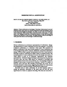
Figure 1 is a simplified block diagram of a typical electronic system in two versions-one using centralized power supplies and a second using distributed power. In each system, the logic is distributed between six boards, each with a requirement for a specific power level and one or more different voltage levels. To use centralized power systems, the designer provides central supplies at 5, 12 and 15 volts, a central filtering and thermal management system, and interconnect wiring to the boards. For the distributed power version of the same system, one central 28-volt nominal bulk supply is provided, and DC/DC converters supply the power levels needed at the appropriate voltages. When a board needs multiple voltages, dual or triple outputs are used. In the distributed system, most of the converters are placed on the single board for which they are supplying power. However, it is also possible to use a single converter with enough power to serve several boards. These higher level distributed power supplies may be board-mountable, but at higher wattage levels (above 200 watts) are more likely to be cage-mounted. The general principles of distributed power design are straightforward, but two significant problems inevitably must be solved when power supplies are moved from a central location to the point of use. The first of these is noise: when several switching power supplies are placed in the system, conducted and reflected ripple from the converters themselves needs to be measured and controlled. The second is heat: when power supplies are compressed into small cases and mounted on logic boards, the designer must
Page 1 of 7 Rev C - 20061206
Crane Aerospace & Electronics Power Solutions
Designing with a Distributed Power Architecture Application Note
also ensure that heat generated during the conversion process is dissipated.
Controlling Noise
All switching DC/DC converters first transform a DC input voltage to an AC voltage and then convert the AC voltage back to the desired DC voltage. The conversion to AC supports step-up as well as step-down functions and allows greatly improved efficiency compared with linear converters. The transformer also provides electrical isolation from input to output. There are many different schemes used to make the DC to AC transformation, but they all generate unwanted signals that can be conducted or transmitted throughout a system. The magnitude of these signals is determined by the frequency of the AC voltage, internal and external filtering, and at high frequencies (above about 1 MHz) the converter’s mounting and connection scheme. They are also affected by the nature of the switching
noise, but their load-dependent variable switching frequencies tend to generate noise over wide frequency excursions, making them difficult to control. For any kind of converter, however, it is important to measure and control the three most significant types of noise: input differential noise, input common mode noise, and output noise. The following section briefly defines each type, suggests measurement techniques, and identifies attenuation strategies. It is also important to note before discussing filter design that effective filtering may require detailed technical information about the converter. Converter manufacturers are happy to provide the data needed, and often they can supply filters as standard products which are designed to work with their own converters.
Input Differential Noise
Input differential mode noise is noise current that flows because of a voltage difference between the two input conductors. The input noise of a converter can be modeled as shown in Figure 2. The converter switching transistor or transistors are simulated by a switch F. which turns on and off at the switching frequency of the converter. The load is simulated by a variable resistor R~L that changes with the load. L and C make up an input filter built into the converter. Nearly all converters will have an input capacitor, and most will have at least a small series inductance as well.
A typical electronic system is implemented in two ways: with a central power source (a), and with a distributedpower scheme (b). The distributed scheme illustrates the simplification and elimination of redundant wiring that can be achieved using that methodology.
In the test setup of Figure 2, a voltage measurement is made across the input terminals of the converter Figure 1: Centralized Power vs. Distributed Power with a voltage probe. The quantity measured is the input ripple current times the topology that generates them. In general, pulse-width moduequivalent source impedance. If the source supply and the test lated converters that keep a constant switching frequency create setup never changed, the noise from different converters could noise in a predictable bandwidth that can facilitate attenuation. be directly compared. But to measure the actual ripple current, Resonant or zero-switching converters can create less intrinsic www.craneae.com
Page 2 of 7 Rev C - 20061206
Crane Aerospace & Electronics Power Solutions
Designing with a Distributed Power Architecture Application Note
the source impedance must be known, and source impedances depend on poorly controlled parameters of the components in the output of the source supply. At frequencies above a megahertz even placement of wires on the bench will make a significant difference in the measured results. If an ideal, zero impedance source could be used, the measured noise voltage would always be zero, no matter how high the noise current. More accurate test results can be obtained by the test setup of Figure 3. Here, the noise current of the converter is measured directly with a current probe so the source impedance Zs will make little difference in the current measured. The effects of Zs are further reduced by the bypass capacitor CB which should be a high quality unit with small series inductance and resistance over the frequency band of interest (usually the switching frequency and above). The connection wires from CB to the converter should be as short as possible to minimize parasitic inductance and radiated noise. If the converter’s internal filtering is not sufficient to attenuate the differential noise to the levels needed in the system, additional LC sections may be added on the input. The capacitors should be quality tantalums with low equivalent series resistance (ESR) and equivalent series inductance (ESL) over the frequency band being filtered. Pot cores are typically used for the inductors. For the filter to work correctly, the Thevenin impedance on the converter side of the filter must be lower than the input impedance of the converter. This is important because all switching power supplies are constant power, negative input impedance devices. As their input voltage goes up, the input current must go down to keep the input power approximately constant. Since the input impedance of the converter is negative and the output impedance of the added filter will be positive, it is possible for them to cancel-to zero at some frequencies and become unstable. Consequently, accurate information from the manufacturer about the input impedance of the converter is crucial when designing the filter.
Input Common Mode Noise
Figure 4 shows how to measure input common mode noise. In a DC/DC converter, switching transistors are typically mounted in close thermal contact with the chassis. To maximize heat transfer the electrical insulation between the collector or drain of the switching transistor is made as thin as practical. This creates a parasitic capacitance from the drain or collector of the transistor to the chassis. When the switch opens or closes, noise current will flow from the switch through the parasitic capacitance, through RL and C, and then through the ground connection back to the chassis. This noise current is small because the parasitic capacitance is small (typically < 10 pF), but an LC filter in the converter is ineffective against it because the current flows around it instead of through it. The common mode noise can be filtered with a balun as shown in Figure 5. A balun is an www.craneae.com
SOURCE ZS
+ RL VIN _
FS
Input differential-mode noise is current that flows in a power system because of a voltage difference between the two input conductors. To control such noise, it must first be measured. Taking a voltage measurement across the converter’s input terminals reveals the input ripple current multiplied by the equivalent source impedance. Figure 2: Simplified INput Differential Mode Noise Measurement
inductor with two windings, both with the same number of turns. The balun presents a high inductance to the common mode current, but virtually none to the differential mode current. Note that the dots on the balun are both on the input side of the converter. This means that the differential current (including the load current) flows into the dot in the top winding and out of the dot on the bottom winding. Since the currents are equal but opposite and the turns in both windings are the same, the net flux in the core caused by the differential current is zero, even though the load current can be very high. As a result a high permeability ungapped core can be used for the balun, and it can have a relatively high common mode inductance with only a few turns. The much smaller common mode noise current flows primarily through the bottom winding and through both windings in the same direction. Thus the balun represents a high impedance to common mode noise currents.
Output Noise
Output ripple voltage measurements are difficult to make even under the best conditions. Depending on the technique used, results may vary widely. As with input noise current, there are two components of output voltage ripple: differential and common mode. Common mode output noise is usually dominated by current conducted through stray capacitances to the AC power line. It is of little interest in most system designs, but it does cause problems when measuring output ripple. The common mode component may have a bandwidth of several tens of megahertz, an area where most oscilloscopes have poor common mode rejection. As a
Page 3 of 7 Rev C - 20061206
Crane Aerospace & Electronics Power Solutions
Designing with a Distributed Power Architecture Application Note
SOURCE
CONVERTER
ZS
RL
CB
FS
result, common mode noise may appear as differential noise.
Spectrum analyzer
A more accurate reading of input differential-mode noise can be obtained by measuring it directly with a current probe. Using this method, the source impedance has little effect on the measured current. Adding bypass capacitor CB reduces the effects of the source impedance of the current measurement even more.
External Filters
Converter manufacturers frequently manufacture external filters for customers who require very low noise. Input filters are the most common, but output filters are also sometimes found. The manufacturer should insure that there are no stability problems when the filter is used with their converters. A quality manufacturer will also have specialized knowledge of high frequency RF layout techniques that most systems manufacturers lack. The improvement in noise performance can be considerable. For instance, Figure 7 shows the input noise spectrum from an Interpoint MHF+ 15-watt converter without added filtering. Figure 8 shows the same converter’s input noise with an Interpoint FM704A filter. The noise is reduced well below the stringent requirements of MIL-STD-461C (CE03), Conducted Emission
ZS
Figure 3: Direct Input Differential Mode Noise Measurement
CB
Consequently, when measuring output differential noise, it is best to connect input and output commons to case, and to use the case as a single point ground for all test equipment to minimize common mode interference. The output differential noise is the noise voltage that appears between the two output terminals. The method used at Interpoint to measure differential output ripple is shown in Figure 6. The measurement must be carried out at the output pins of the converter to reduce the pickup of radiated noise. The 50-ohm series resistor and the 50-ohm terminating resistor are for impedance matching to the 50-ohm coaxial cable. Lead lengths, including the ground lead must be as short as possible to reduce the pickup of radiated noise. An optional parallel capacitance of 2700 pF at the scope will reduce the bandwidth to approximately 2 megahertz to permit viewing of the fundamental frequency component of the ripple. If the converter’s internal output filtering is not sufficient to bring the noise levels within system requirements, additional LC sections may be added on the output. Like the input filter, the capacitors should be quality tantalums with low equivalent series resistance (ESR) and equivalent series inductance (ESL) over the frequency band being filtered. If only high frequencies are being filtered, a good ceramic capacitor may be adequate. Pot cores are also typically used for output inductors. If the corner frequency of the added LC filter approaches the bandwidth of the converter’s internal control loop (nearly always