Detection and Location of People in Video Images Using Adaptive Fusion of Color and Edge Information Sumer Jabri, Zoran Duric, Harry Wechsler Department of Computer Science George Mason University Fairfax, VA 22030 {sjabri,zduric,wechsler}@cs.gmu.edu
Azriel Rosenfeld Center for Automation Research University of Maryland College Park, MD 20742-3275
[email protected]
Abstract A new method of finding people in video images is presented. Detection is based on a novel background modeling and subtraction approach which uses both color and edge information. We introduce confidence maps—gray-scale images whose intensity is a function of our confidence that a pixel has changed—to fuse intermediate results and to represent the results of background subtraction. The latter is used to delineate a person’s body by guiding contour collection to segment the person from the background. The method is tolerant to scene clutter, slow illumination changes, and camera noise, and runs in near real time on a standard platform.
1
Introduction
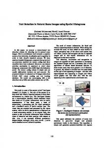
Many authors have developed methods of detecting people in images [1, 2, 3, 4, 6, 7]. Most of this work has been based on background subtraction using color or luminance information. The results usually suffer from false positives/negatives when conditions are not favorable. In this paper, we present a novel background subtraction method that utilizes both color and edge information to improve the quality and reliability of the results and overcome some of the difficulties faced by existing methods. Our approach is divided into three main parts: (i) building and maintaining the background model, (ii) performing background subtraction, and (iii) delineating the foreground. We will illustrate our method using the images shown in Figure 1. These images were collected at the Keck Laboratory at the University of Maryland in College Park using a SONY progressive 3CCD digital camera; the images are RGB color, and the frame rate was sixty frames per second.
Figure 1. Frames 125 and 225 from a 300frame sequence of a moving human.
2
Building the Background Model
The background is modeled in two distinct parts, the color model and the edge model. For each color channel, the color model is represented by two images which hold the mean and standard deviation of that color component in a video sequence of the static background scene. The mean image is computed at each pixel as a weighted mean µt = αxt + (1 − α)µt−1 where µt is the mean computed up to frame t, α is the learning rate of the model, and xt is the pixel value in frame t. In effect, this computes an exponentially weighted mean of all the previous values of the pixel. Subtracting incoming video frames from this mean will allow us to identify pixels that have changed color. The standard deviation image σt is defined by 2 . σt2 = α(xt − µt )2 + (1 − α)σt−1
It will be used in the confidence normalization phase during background subtraction. The edge model is built by applying the Sobel edge operator to each color channel. This yields a horizontal difference image H and a vertical difference image V . Weighted means Ht and Vt and standard deviations
are computed as in the color model. We maintain horizontal and vertical Sobel responses separately in order to preserve gradient direction information; whenever the gradient magnitude is needed, we compute it from these responses. This model will be used to locate changes in the structure of the scene as edges appear, disappear, or change direction. Even in a static scene, frame to frame changes occur due to noise, camera jitter, and varying illumination. These factors are quite difficult to control. Therefore, to preserve the validity of our background model we update the mean images continuously. Figure 2 shows the images µ60 , H60 , and V60 computed from the green channel of the sequence illustrated in Figure 1.
these confidence maps for frames 125 and 225 in the sequence of Figure 1 are shown in Figure 3.
Figure 3. Color subtraction result for frames 125 and 225 of the sequence in Figure 1.
3.2 Edge-Based Subtraction
Figure 2. Mean images for color, horizontal edges, and vertical edges (green channel shown) at the 60th frame of the sequence.
3
Background Subtraction
Background subtraction is performed by subtracting the color channels and edge channels separately and then combining the results.
In the edge subtraction phase, we take into account the changes in both edge magnitude and edge direction. In this phase we also classify edges as foreground edges, occluded background edges, and background edges. For each color channel, we subtract the current x and y difference images from the corresponding mean images: ∆H = |H − Ht |, ∆V = |V − Vt | where H and V are the horizontal and vertical differences in the current frame and Ht and Vt are the mean horizontal and vertical differences. We then define the edge gradient as ∆G = ∆H + ∆V.
3.1 Color-Based Subtraction In the color subtraction phase, we subtract the current video frame from the stored mean image. This is done for each color channel, resulting in three difference images. Next, we perform a confidence normalization step for every channel using two thresholds, mσ and M σ, derived from the standard deviation images. If the value of the difference is below mσ the confidence is set to 0%, if it is above M σ the confidence is set to 100%; for intermediate values of the difference, the confidence is scaled linearly: Cc =
D − mσ × 100 M σ − mσ
where D is the difference value. Since change in any color channel can be an indicator of a foreground region, we take the maximum of the three confidence images. The higher the value of this maximum at a pixel, the more confident we are that the pixel belongs to the foreground. Examples of
We now describe how we assign confidences to those ∆’s. To illustrate this, suppose we have two background edges, one having magnitude 50 and the other 100. In the incoming video frame, suppose both edges change magnitude by the same amount, 10. The stronger edge has thus changed by 10%, whereas the weaker edge has changed by 20%—a much more significant change. The ratio of the difference to the strength of the edge can be used to express our confidence in the difference; we call it the edge reliability R. It is computed as follows: Let G = |H| + |V |, Gt = |Ht | + |Vt |, G∗t = max{G, Gt }. Then R=
∆G . G∗t
We use this R to weight the edge gradient difference: R∆G. The confidence that a pixel belongs to the foreground based on the edge strength in a color channel
is then Ce =
0%
R∆G−mσ Mσ−mσ
100%
× 100%
R∆G < mσ mσ ≤ R∆G ≤ M σ R∆G > M σ
Figure 5 shows the result of this step for frames 125 and 225. It can be seen that the color and edge results complement one another to yield well-defined foreground objects.
where σ is the sum of the standard deviations in the horizontal and vertical directions. The final confidence map is then built by taking a maximum of the three computed confidences; it is illustrated in Figure 4.
Figure 5. Combined subtractions for frames 125 and 225 of the sequence in Figure 1.
Figure 4. Edge subtraction result for frames 125 and 225 of the sequence in Figure 1. This phase also classifies the edges using the following rules:
A single median filtering step is applied to the resulting confidence map to remove salt and pepper noise, i.e. to fill holes in regions of high confidence and remove isolated pixels in regions of low confidence. The final output of this step is a confidence map based on both color and edge subtraction results, as illustrated in Figure 6.
1. Occluding Edges: These are edges of objects that have entered the scene. They occur when there is a significant difference in some channel between the mean and current frames, and there is an edge in the current frame of significant strength, i.e. Gt ≥ mσ. 2. Occluded Edges: These are background edges that have been occluded by objects. They occur when there is a significant difference between the mean and current edges, and there is no significant current edge. 3. Background Edges: These are mean edges that have not changed. They occur when there is no difference between the mean and current edges. The edge subtraction phase produces two outputs: a confidence map of foreground edges, and an edge image in which edges have been classified as occluding, occluded, or background.
3.3 Combining the Color and Edge Subtraction Results We combine the color and edge confidence maps by taking their maximum: C = max{C c , C e }
Figure 6. Combined subtraction results after median filtering for frames 125 and 225 of the sequence in Figure 1.
4
Locating and Delineating the Foreground
The foreground represents the objects that have entered the scene; it is defined by the gray level foreground confidence map, and by the contour that delineates the foreground objects from the background. We use a connected components algorithm to label connected regions in the confidence map. A hysteresis thresholding step is then applied to remove false positives by eliminating all components that are not connected to a 100% confidence region. The resulting binary map, shown in Figure 7, contains the foreground regions detected by the our method; it is stored in our foreground model as the first representation.
lected using a SONY CCD TR500 Handycam (Camera 2). The four system parameters were set to mc = 15 me = 3 Mc = 25 Me = 9
Figure 7. Connected components after hysteresis thresholding for frames 125 and 225 of the sequence in Figure 1.
where mc and Mc are the color thresholds, and me and Me are the corresponding edge thresholds. These thresholds were not changed or tweaked for any of the sequences. Additional results can be viewed at http://www.cs.gmu.edu/∼sjabri/research/.
5 Finally, we extract the contours of these regions using a contour following algorithm. The resulting contours, shown in Figure 8, are stored in our foreground model as the second representation.
Figure 8. Collected contours for frames 125 and 225 of the sequence in Figure 1. Figure 9 shows the segmented human with the contour overlaid in white to demonstrate the quality of segmentation and how well the delineating contour fits the human.
Figure 9. Segmented human for frames 125 and 225 of the sequence in Figure 1. The collected contours are overlaid in white over the image. Our method was tested on 14 different video sequences, collected under various conditions [5]. These included 5 indoor sequences, using a SONY 3CCD progressive digital camera (Camera 1), with two kinds of illumination conditions: halogen and fluorescent. The remaining 9 sequences were outdoor sequences col-
Conclusions
The new method for detecting and locating people proved to be tolerant to camera noise and slight illumination changes. In addition, since edges are used in subtraction, this approach makes use of, and indeed favors, clutter in both the scene and the human (clothing, etc.). It could be used as a first step toward more task-specific research such as automated surveillance, augmented reality, human gesture recognition, human computer interaction, and very low bandwidth communication.
References [1] J.W. Davis and A.F. Bobick. The representation and recognition of human movement using temporal templates. In Proc. Computer Vision and Pattern Recognition, pages 928–934, 1997. [2] L.S. Davis, D. Harwood, and I. Haritoaglu. Ghost: A human body part labeling system using silhouettes. In Proc. ARPA Image Understanding Workshop, pages 229–235, 1998. [3] D.M. Gavrila and L.S. Davis. 3D model-based tracking of humans in action: A multi-view approach. In Proc. Computer Vision and Pattern Recognition, pages 73– 80, 1996. [4] I. Haritaoglu, D. Harwood, and L. Davis. W4S: A realtime system for detecting and tracking people. In Proc. Computer Vision and Pattern Recognition, pages 962968, 1998. [5] S. Jabri. Detecting and delineating humans in video images. Master’s thesis, Computer Science Department, George Mason University, Fairfax, Virginia, September 1999. [6] S.X. Ju, M.J. Black, and Y. Yacoob. Cardboard people: A parameterized model of articulated image motion. In Proc. International Workshop on Automatic Face and Gesture Recognition, pages 38–44, 1996. [7] C. R. Wren, A. Azarbayejani, T. Darrell, and A. Pentland. Pfinder: Real-time tracking of the human body. IEEE PAMI, 19:780–785, 1997.