Jun 4, 2015 - Belirlenmesi," Tekstil Teknolojileri Elektronik Dergisi, vol. 6, pp. 22-39, 2012. [2] C. Cork, W. Cooke, and J. Wild, "The use of image analysis to ...
ISBN 978-93-84422-22-6 Proceedings of 2015 International Conference on Image Processing, Production and Computer Science (ICIPCS'2015) Istanbul (Turkey), June 3-4, 2015 pp. 83-88
Determination of Yarn Twist Using Image Processing Techniques Kazım Yıldız1, Zehra Yıldız2, Önder Demir1 and Ali Buldu1 1
Marmara University, Technology Faculty, Department of Computer Engineering 2 Marmara University, Technology Faculty, Department of Textile Engineering
Abstract: In this study, a new quantitative method has been improved to determine the yarn twist values by using image processing techniques. For this purpose, firstly some sewing yarn images have been taken by a light microscope then these images have been processed by using image processing techniques. The obtained twist values via image processing have been compared to the actual yarn twist results. The accuracy percentage of the image processing technique on determination of yarn twist values has been measured. Results proved that yarn twist value can be determined by image processing technique with an average 90% accuracy without any yarn twist tester. Keywords: image processing, yarn twist, sewing yarn, thresholding, median filter.
1. Introduction Image processing techniques are used as an effective as well as in many research field such as biomedical engineering, chemistry, materials science and textiles. Image processing is used in a wide variety for analysis of fiber and yarn structures, quality control, determination of the warp/weft densities in woven fabrics and presence of the power assisted composites in textile [1-3]. The notion of “twist” means the spiral rotation that is needed for holding the fiber bundles together and giving tenacity to the yarn. Twist is given to textile yarns during the spinning processes in textile industry. Twist in fiber, is important for the purpose of using conditions. Yarn twist can be explained by giving the twist value per meter (T/m) or per inches (T/”). Number of twist affects the characteristics of the yarn such as strength, elasticity and appearance. The twist ration is completely depends on the end-user desires and can be set in spinning mills [4]. Twist measurement is performed with warp measuring devices in the textile industry. This is convenient ways to make the measurement standards at least 25 cm thread samples are needed. [5]. Chiu and colleagues tested the cellulose fiber reinforced polylactic acid composite material's mechanical properties with experimentally then there properties are estimated with image processing techniques. Neagu and friends characterized a variety of animal, herbal and synthetic fibers cross section microscopic images by using image processing techniques. The other field that image processing techniques are used as follows; analysis of polyester/rayon composite yarn cross section images, investigation of fiber migration to the yarn center during the bamboo/cotton vortex yarn manufacturing [6-9]. In this study, it was aimed to measure the yarn twist values in small dimension yarn samples (2.5 cm) without using any yarn twisting instrument. For this purpose images of the four different sewing threads have been taken with a light microscope then twisting quantities were calculated with image processing. The actual yarn twist values also have been measured by using yarn twist measurement instrument in order to compare it to the image processing results. Results proved that with a great accuracy yarn twist value can be determined just by using image processing technique. Therefore warp measuring device usage can be eliminated. Furthermore this study is hopeful for archeological researches when only small pieces of yarn samples are available.
http://dx.doi.org/10.17758/UR.U0615024
83
2. Materials and Method In this study four different 100 % polyester sewing yarn samples having different color and twist values have been purchased from Coats Co. The twist values have been measured by using a yarn twist tester (Prowhite).
Fig. 1: Light microscopy.
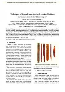
The yarn images from 2.5 cm length have been captured by using a light microscopy (Dino-Lite) that can be seen in Figure 1. By using these images yarn twist values have been measured with the help of image processing techniques. Figure 2 shows the yarn samples images that were captured by light microscopy. In this study different structure and twisting yarns are used for the purpose of measuring the accuracy of the developed technique.
A
B
C D Fig. 2: Light microscopy images.
2.1.
Image Processing and Analysis
By using image processing techniques and yarn images, the twist values of the yarns have been measured. Figure 3 shows the block diagram of the developed system.
http://dx.doi.org/10.17758/UR.U0615024
84
Fig. 3: Block Diagram of the Developed System.
First of all the gray level image is obtained. Then median filter is used for cleaning the horizontal fiber of image. Also the noise of the image is cleaned with the help of the median filter. Median filtering is defined as a non-linear operation. It is allowed to more selective results on image according to linear filtering. It is effective for cleaning of the noise in the form of impulses especially [10]. The destination pixel values is calculated according to the average of the neighboring pixels. The equation of the median filtering process as seen: (1) (2) (3)
The median filter is obtained by getting closer the pixels having counter values to the neighboring pixel values onto the image. The outlier values are referred to the noise on the image [11]. The thresholding process is used for the purpose of cleaning the noise on the image[12]. A range of threshold values for the pixels that make up the structure, multiple-threshold value may be applied. These threshold values are called for the lower limit as "minimum density threshold and the upper limit as "maximum density threshold”. The pixel values that are lower than the minimum intensity threshold and greater than the maximum intensity threshold are assigned to "0", these areas are guaranteed to be black on image. Thresholding process provides decreasing runtime of the system [13-15]. Figure 4 (a) displays a gray level image matrix and figure 4 (b) displays the image matrix after thresholding with minimum intensity threshold is 80 and maximum intensity threshold is 180.
Fig.4: (a) Gray Level Image Matrix
(b) Thresholded Image Matrix
After the thresholding process image is converted to the binary level image. The biggest area is detected on the binary level. For the detection process on binary images, the adjacency examination study is done. The technique of conducting an adjacency examination on binary images is used quite frequently to identify abnormal forms in numerous image processing applications. A procedure can be performed on the actual image using the coordinates of the forms identified on the binary image as a result of the adjacency examination. Conducting an adjacency examination on binary images involves the identification of values of 1 present on adjacent pixels. For all pixels with a value of 1, all the adjacencies of every pixel in all 8 directions are checked; this process is repeated for every adjacent pixel with a value of 1. When the adjacency examination is performed for a minimum number of adjacencies, small forms are ignored in order to simplify the calculation. The identified adjacencies are specified on a label matrix. This label matrix is convenient for morphological feature extraction procedures to be performed on adjacencies for which the
http://dx.doi.org/10.17758/UR.U0615024
85
label matrices have been identified. The coordinates of the label numbers included in the label matrix can also be accessed on the actual image in order to perform feature extraction on the basis of intensity values [16-18]. Figure 5 displays an adjacency identification performed from the results of an adjacency examination with a minimum of 4 adjacencies. The actual binary image matrix is represented in Figure 5 (a), while Figure 5 (b) shows the adjacencies that were identified, labeled, and not labeled. The label matrix created as a result of that particular adjacency examination is presented in Figure 5 (c).
Fig.5: (a) Binary Image Matrix (b) Detected Adjacencies (c) Labeled Adjacencies
The horizontal areas which are determined in the vertical structure of yarn, top values have been counted for twisting number. By comparing the actual values with the values obtained from here the accuracy rate is obtained. Figure 6 shows the image of the yarn samples after image processing steps. Firstly, the image was converted onto the black and white then the highest area in that image has been found. In order to measure the yarn twist the width (diameter) of the yarn has been detected. Considering the diameter values in horizontal line, the highest values have been accepted as peak values. Thus the yarn twist can be found in twist per meter (T/m).
Fig.6: The image processing application onto the yarn image and yarn twist-yarn width chart.
3. Results and Discussion In this study, an image processing application developed to eliminate yarn twist tester devices and to determine yarn twist on very short yarn samples. For this purpose four different polyester sewing yarn images are taken with light microscope and these images are used in to determine twisting number. First median filtering is used on images. With the help of median filter, it is aimed to remove noisy areas from yarn images. In the some of the yarns, horizontal hairiness is going to be decrease. Median filtering was successful in the horizontal direction in the process of cleaning. Then the thresholding values that are detected empirically are used for pixel value thresholding. So the images are converted to binary level. With the using this binary images, the horizontal area are measured. Measured horizontal areas are used to determine number of yarn twist. http://dx.doi.org/10.17758/UR.U0615024
86
In Table 1, the values which obtained with light microscope and image processing techniques were given together. The results are shown the different types of yarns, and the applications is achieved an accuracy rate of about %90 worth. TABLE I: The Yarn Twist Values Obtained From Both Twist Tester And Image Processing Technique, And The Accuracy Rate. Sample Code A B C D
Twist value from twist tester (T/m) 374 437 426 186
Twist value from image processing (T/m) 391 434 478 217
Accuracy % 94.6 99.1 89.1 85.7
4. Conclusion In this study firstly images of the different types of sewing yarns have been captured by using a light microscopy. By using light microscopy images and image processing techniques, the yarn twist values have been calculated. Yarn twist values also have been measured by using a yarn twist tester. Results that are obtained from twist tester and image processing have been compared. According to the results, image processing technique can be employed in yarn twist measurement with a over 90% accuracy. The main advantage of this technique is that, it is possible to find yarn twist value only by using small amount of samples even 2.5 cm in length. That is so important for archeological research. Furthermore, image processing usage in twist measurement can eliminate the twist tester in textile industry. Results proved that because of the high hairiness value in the sample of C and loose twist structure in the sample of D, the image processing accuracy rate is lower than A and B. Further studies will be in the way of using double threshold and obtaining the yarn diameter more accurately. Additionally, a newly designed filter can be used in order to decrease the noise onto the image with median filter.
5. References [1] H. İ. Çelik, L. C. Dülger, And M. Topalbekiroğlu, "Görüntü İşleme Teknikleri Kullanarak Kumaş Hatalarının Belirlenmesi," Tekstil Teknolojileri Elektronik Dergisi, vol. 6, pp. 22-39, 2012. [2] C. Cork, W. Cooke, and J. Wild, "The use of image analysis to determine yarn twist level in archaeological textiles," Archaeometry, vol. 38, pp. 337-345, 1996. http://dx.doi.org/10.1111/j.1475-4754.1996.tb00781.x [3] K. Yildiz, V. Y. Şenyürek, Z. Yildiz, and M. S. Özen, "A New Approach to the Determination of Warp-Weft Densities in Textile Fabrics by Using an Image Processing Technique," Journal of Engineered Fabrics & Fibers (JEFF), vol. 9, 2014. [4] http://iplikonline.com.tr/v1/kultur/iplik_kalite_parametreleri.php. (2015, January, 2015). İplik Kalite Parametreleri. [5] "TS EN ISO 2061:Tekstil- İpliklerde büküm tayini- Doğrudan sayma metodu," ed, 2010. [6] S.-H. Chiu, J.-Y. Chen, and J.-H. Lee, "Fiber recognition and distribution analysis of PET/rayon composite yarn cross sections using image processing techniques," Textile research journal, vol. 69, pp. 417-422, 1999. http://dx.doi.org/10.1177/004051759906900605 [7] R. Neagu, M. Cuénoud, P. Bourban, F. Berthold, E. Gamstedt, M. Lindström, et al., "The Potential of Wood Fibers as Reinforcement in Cellular Biopolymers Standard," Submitted to Journal of Cellular Plastics, 2011. [8] B. Xu, B. Pourdeyhimi, and J. Sobus, "Fiber cross-sectional shape analysis using image processing techniques," Textile research journal, vol. 63, pp. 717-730, 1993. http://dx.doi.org/10.1177/004051759306301204 [9] S. Zheng, Z. Zou, W. Shen, and L. Cheng, "A study of the fiber distribution in yarn cross section for vortex-spun yarn," Textile research journal, vol. 82, pp. 1579-1586, 2012. http://dx.doi.org/10.1177/0040517511431315 [10] V. Musoko and A. Procházka, "Non-Linear Median Filtering of Biomedical Images," Institute Of Chemical Technology, Department Of Computing And Control Engineering. [11] H. Hwang and R. Haddad, "Adaptive median filters: new algorithms and results," Image Processing, IEEE Transactions on, vol. 4, pp. 499-502, 1995. http://dx.doi.org/10.1109/83.370679 [12] Doğan T., Sert E., and Taşkın D., "Araç Destek Sistemleri İçin Kuş Bakışı Görüntü Dönüşümü," in Akademik Bilişim, 2013.
http://dx.doi.org/10.17758/UR.U0615024
87
[13] A. P. Dhawan, Medical image analysis vol. 31: Wiley-IEEE Press, 2011. http://dx.doi.org/10.1002/9780470918548 [14] N. Otsu, "A threshold selection method from gray-level histograms," Automatica, vol. 11, pp. 23-27, 1975. [15] M. Sezgin and B. Sankur, "Survey over image thresholding techniques and quantitative performance evaluation," Journal of Electronic imaging, vol. 13, pp. 146-168, 2004. http://dx.doi.org/10.1117/1.1631315 [16] P. A. Devijver, Connected components in binary images: the detection problem: John Wiley & Sons, Inc., 1984. [17] L. Di Stefano and A. Bulgarelli, "A simple and efficient connected components labeling algorithm," in Image Analysis and Processing, 1999. Proceedings. International Conference on, 1999, pp. 322-327. http://dx.doi.org/10.1109/iciap.1999.797615 [18] M. Manohar and H. Ramapriyan, "Connected component labeling of binary images on a mesh connected massively parallel processor," Computer vision, graphics, and image processing, vol. 45, pp. 133-149, 1989 http://dx.doi.org/10.1016/0734-189X(89)90129-1
http://dx.doi.org/10.17758/UR.U0615024
88