and airbag system supplied by Honda, and horn direct measurements of a 1997 Honda Accord. The seat drawing was used to position the airbag correctly ...
DEVELOPMENT AND APPLICATION OF A SIDE AIRBAG MIJLTI-BODY DYNAMICS PROGRAM
COMPUTER
MODEL
USING THE CVS/ATB
Edwin Sieveka Jeff Crandall Stefan Duma Walter Pilkey University of Virginia Paper Number 9%S9-O-05 obtain qualitative information about the kinematics that could result from each airbag interaction, as well as to estimate the relative load levels expected in the occupant’s arm. This information was helpful in refining the laboratory test matrix to achieve greater efficiency and costeffectiveness by identifying the worst cases. Computer runs were performed to show the effects of occupant size, position, and clavicle flexibility. .The latter distinguished between the response anticipated for Hybrid III dummies versus relaxed humans. Most of the runs simulated the laboratory’s static deployment configuration, but several runs were also made which exercised the model in a fullmotion, door-intrusion event. All simulations were made with an airbag that approximated Honda’s medium-energy bag.
ABSTRACT A new computer model for studying side airbag and occupant interactions was developed for the CVSJATB multi-body dynamics program. This model employs standard CVS/ATB segment ellipsoids to represent the airbag. Bag stiffness is represented by a standard force vs. penetration contact function, however, the CVSIATB program code was modified to allow the sti&ess function to be multiplied by an additional, time dependent scaling function. This permits simple simulation of bag inflation and deflation without direct modeling of hydrodynamic bag parameters. The 5th and 50th percentile occupant models were originally obtained from the GEBOD program. These models were modified to incorporate clavicle segments. The additional shoulder freedom, permitted by extensive clavicle motion, results in significant kinematic differences between H3-type dummies and cadavers when performing side airbag tests. In the computer simulations, dummy cases are represented with a locked clavicle joint, while for cadaver cases the clavicle is permitted to move relative to the torso. This model has been exercised for a variety of potential occupant seating positions and has proven effective in distinguishing differences in load and kinematics. This in turn has helped guide the choices made for laboratory experiments such that testing efficiency is maximized.
MODEL
DESCRIPTION
Occupant Compartment
Dimensions
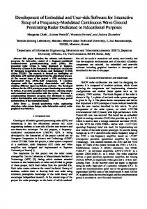
The occupant compartment in the CVS/ATB model was constructed with measurements from a drawing of the seat and airbag system supplied by Honda, and horn direct measurements of a 1997 Honda Accord. The seat drawing was used to position the airbag correctly relative to the seat and to size the airbag accurately. The Accord measurements were used to ensure that the seat was properly positioned relative to the inside and the top of the door, and relative to the arm-rest. The oblique and side views of the final model geometry, including a 5th percentile female occupant, are shown in Fig. 1.
INTRODUCTION As part of the University of Virginia’s Automobile Safety Laboratory (ASL) study of Honda side-impact airbags, models were developed for use in the CVWATB multi-body dynamics program. In contrast to other recent modeling efforts which make extensive use of finite elements [ 1,2], the models described in this paper are multi-body only and run on current Pentium PCs in one or two minutes. These models, of 5” percentile female and 50* percentile male occupants in various positions, were used to efftciently
Airbag Model The CVWATB airbag model was adapted from an earlier driver-bag model [3]. The bag geometry was approximated by a combination of 5 CVS/ATB ellipsoids, comprising a primary bag and 4 secondary bags. The initial position and shape is shown in Fig. 1. To simulate inflation, the bag begins behind the seat and is forced along a track (slip-joint) by a forcing function that is based on the pressure time-history horn Honda tests and from the
1925
The forcing function was modeled as a II4 sine from the moment of punchout (at about 5 ms) until 10 ms. In this short time interval, the bag is almost totally deployed; hence, in the model, the bag must move f?om behind the seat to its deployed position (about 32 cm) in about 5 ms. This combination of time, travel distance, and force tinction shape, along with the weight of the bag, allows the peak magnitude of the force function to be determined. For a l/4 sine wave impulse of duration T, the maximum acceleration, A, versus the distance traveled, D, is given by:
observation of a high-speed film of a bag deployment test. The time-history curve is shown in Fig. 2.
A = (z2 * D) / (4 * T*) . If I%32 cm and T=.005 set, then A = 3.158 * lo6 cm/set* or 3222 G’s_ For the airbag, which weighs about 1.25 N, the peak force required is 4028 N. In tuning the model, a maximum force closer to 5000 N was needed to compensate for the loss of energy associated with the door impact.
L
Figure 1. Model geometry: views.
A stiff spring, which is initially slack, defines the end of the track and stops the deployment of the bag. Equilibrium between this spring and the post-deployment forcing function keeps the bag in position. The slip-joint connecting the primary bag to the track also allows rotational motion via a superposed ball-joint. This permits the bag to rotate as it encounters the door and to assume the correct post-deployment orientation. The four secondary bags are deployed in a slightly different manner. Each is connected to the primary bag by a pair of springs. One spring is initially slack and functions as the stop, or tether, spring. The other spring is pre-loaded and drives the deployment. The slip-joints connecting the primary and secondary bags are initially locked at a value just above the pre-load value in the deployment spring. The forcing function in this case is used as a trigger to unlock the slip joints. ARer that, the secondary bags move out from the primary bag until equilibrium is reached between the deployment spring and the tether spring. This method ensures that a force applied to one of the secondary bags is transmitted to the whole bag system. If external forcing functions were used to deploy the secondary bags, there would be no load transmitted to the primary bag when the secondary bags were loaded. The fully-deployed bag shape is shown in Fig. 3.
I
oblique and side
Tim:
(ms)
I
Figure 2. Bag pressure time-history.
1926
possibilities for artifactual results when computing arm-toairbag contact. Note how in an early simulation, the airbag gets “stuck” when the upper arm’s shape is represented by two ellipsoids (Fig. 4).
Figure 3. Shape of the deployed airbag. The actual bag stiEness as seen by the occupant’s arm has been estimated by tuning the arm reaction to that observed in test films. The interaction forces between the bag and the door were inferred in this manner also. Near the end of this phase of the project, UVA’s version of CVUATB was modified to permit the deflation of the airbag to be approximated. This involved changing the program code so that any force/deformation function can be multiplied by a timedependent scaling function. In this way, the force/deformation function used for airbag sti&ess could be made to soften with time. This was needed in order to obtain more realistic results for simulations involving intrusion. These simulations involve extended contact between the occupant and the airbag, and using an airbag that did not deflate caused the forces loading the occupant to be over-predicted. Intrusion study results are described in detail in a later section.
L
Figure 4. Airbag getting “stuck” between upper arm ellipsoids. PARAMETER
STUDIES
Multi-Position
Study
The first study conducted with the new side airbag model was one to determine the relative severity of possible sitting positions with regard to the airbag/arm interaction. Initially, five positions were defined as:
Occupant Arm Model The left arm in the occupant models was enhanced to provide an estimate of the loads experienced at the centers of the upper arm and forearm segments. These segments were each split into two separate segments connected by locked joints. CVS/ATB reports the forces and torques that it applies at these joints to satisfy the locked constraint. These values can be compared directly to load cell measurements. To maintain smooth contact with the airbag, a single ellipsoid was used to give shape to each of the upper arm and forearm segment pairs. This ellipsoid was attached to the segment containing the original, single-segment c.g.. This design introduces the fewest
1. Normal sitting position with forearm flat on the armrest (S), 2. Normal sitting position with forearm flat on the top of the door (6), 3. Occupant reclining against door with upper arm and forearm on armrest (9), 4. Forearm flat against door and upper arm directly in airbag’s path (1 l), 5. Occupant leaning against door with upper arm between seat and door (5). These positions are shown in Fig. 5. The arm positions after 32 ms are shown in Fig. 6.
1927
11 igure 5. Occupant positions for the multi-position
Figure 6. Arm positions after 32 ms.
1928
study.
the airbag contact phase. However, the upper arm experiences rapid rotational acceleration which results in a large spike as the elbow hyper-extends into the joint stop. This spike is, in fact, the largest horn all of these initial simulations. Case 11 demonstrates how the greatest loads may result from secondary effects which occur after the primary airbag contact. Based on these results, a new position was defined which was intended to be a worst case. In this position, described as the Modified 8 position, the occupant was translated sideways until the shoulder was at the edge of the seat and the elbow was just touching the door, but not pressed tightly against it. The occupant was also raised slightly so that the upper arm could lie in the plane of the seat back with the forearm flat against the armrest. This differs horn position 5 in that there is less contact, hence diction, between the arm and the door, and because the exposure of the upper arm to the deploying airbag is maximized. The kinematics from this simulation are shown in Fig. 9 and the moment plots in Fig. 10. Due to its severity, this position was added to the ASL test matrix.
A 5th percentile female occupant was used for all of the runs in this first series. The numbers denote the ASL’s test configuration number. These numbers will be used to refer to each case in the subsequent discussion. Figure 7 shows the mid-humerus X-Y resultant moment for all of the above cases and Fig. 8 shows the elbow X-Y resultant moment for the four worst cases. Mid-Bumems X-Y Resultant Moment
0
10
20
30 lime
Figure 7. Mid-humerus
40
50
(ms)
~I
X-Y resultant moment.
Elbow X-Y Resultant Moment 300 250
E t f E +
20u 150 loo
Figure 9. Modified position 8. 50 0
t 0
10
20
30
40
Comparison of Mid-Humerus Resultant Moments for Positions 5, 1 I, and Modified 8
54
Time (m-s)
I-i
350 -Arm
igure 8. Elbow X-Y resultant moment.
300 250
Case 5 clearly stands out as the worst overall since it involves a large mid-humerus moment during airbag contact as well as a sharp spike in the elbow moment due to hyper-extension 20 ms later. The normal armrest position in Case 8 produces intermediate results, while Case 6 with the arm on top of the door involves relatively little airbag interaction. Of considerable interest are the results from Case 11. In this case, the airbag loads the arm near the elbow joint. This produces a very small mid-humerus torque during
-z 5.
against
door
(11)
~---- Leaning
on door
(5)
-. Modified
Position
0
200
g p 150 2 100
Time
(ms)
Figure 10. Moment comparisons of positions 5,11, and modified 8.
1929
Joint Friction Study Clavicle Effect Study Joints on the Hybrid III (I-U) dummies are normally adjusted so that the arms will fall from a horizontal position with approximately constant angular velocity. Thus the torque generated by joint friction is almost in equilibrium with the torque created by gravity. This is often referred to as 1-G joint friction. Humans on the other hand, have almost zero joint f?iction. Since friction at the elbow and shoulder joints can influence the arm’s response to the airbag, it is important to know if the normal H3 joint f?iction will have a significant effect. To answer this question, Position 8 simulations were run with 1 G and 0.01 G friction at the shoulder and elbow. The plots in Fig. 11 show that, at normal H3 levels, joint f?iction has a negligible effect on arm response.
The occupant models provided by the CVSIATB GEBOD database program do not contain segments representing the clavicles. For the H3-type dummies, this is not a bad approximation because the dummy clavicles are very stiff and have a very limited range of motion. For a human, however, the clavicle accounts for most of the foreaft motion of the shoulder joint complex, and for about l/3 of the range-of-motion when a person is standing and the arm is raised straight up over the head. This additional compliance at the shoulder joint should produce noticeable differences between dummies and humans. In order to examine this effect prior to laboratory testing, the occupant models in the side airbag study were modified to include clavicle segments. These segments were kept locked for dummy-like simulations and were unlocked for human-like simulations. In the latter case, the clavicle joint was allowed to move with only a viscous constraint force until it neared the estimated range of motion. At that point, an angle-dependent spring torque was applied. The three most severe cases from the initial study, 5,9, and 11, were rerun with the free clavicle. Results f?om this study show consistent differences for the locked and fi-ee clavicle joints. In all cases, the calculated arm loads were reduced when the extra degrees of f?eedom were added at the clavicle joint. Thus, arm loads measured with the dummy can be considered a worst-case since they should consistently over-predict the loads that would be experienced by a human in the same situation. These simulation results are summarized by the plots in Fig. 12.
Sensitivity of Upper Arm Accelerations to Elbow and Shoulder Friction
;-AX 1
50
-AY
\'1 \ J -30 i 0
5
10
Solid - IG joint tiicticm Dashed - .OlGjoint friction 15 Time (ms)
20
25
3t
Sensitivity of Forearm Accelerations to Elbow and Shoulder Friction
Mid-Humerus X-Y Resultant Moment Comparison of Locked vs Free Clavicle
Solid - 1G joint friction Dashed - .OlG joint friction
-25
-50 0
5
10
15 Time (ms)
20
25
3c
0
Figure 11. Influence of joint friction on arm accelerations for arm-on-armrest (position 8).
5
10
15
20 Time
25
30
35
(ms)
Figure 12. Results from the clavicle effect study.
1930
41
moment and elbow resultant force are plotted in Fig. 15 along with the 5th percentile female data.. The differences seen in both the plots and pictures are considerable, but do not always indicate a male-to-female difference. In the Modified 8 simulations the fact that the male’s arm is knocked sideways while the female’s is pushed in a more forward direction may have more to do with position subtleties than with arm weight. It does seem likely, however, that the larger initial peak in the male’s mid-humerus moment curve is associated with his arm’s larger inertia, which makes it harder for the airbag to bump it out of the way.
Male vs. Female Study Male and female occupants will interact differently with the airbag because of arm weight and because stature differences produce subtle changes in arm orientation for what are, nominally, the same sitting positions. To examine how these differences might affect test results, simulations of the 50th percentile male were performed for the original and modified position 8 cases. Kinematic results at 48 ms are shown in Figs. 13 and 14. The results for mid-humerus
SMRLL
FENFILE:
TIME(MSEC)
FIRMREST
HID-SIZE
36
TIME(MSEC)
FIRMREST
MQLE: 36
Figure 13. Male vs. female comparison for origina 11farmrest position. SMI?LL
FEMFILE:
TIME(MSEC)
FlRMREST
(MODIFIED)
MID-SIZE
36
TIME(MSEC>
MFILE:
ARMREST 36
Figure 14. Male vs. female comparison for the modified armrest position.
1931
(MODIFIED)
Door Intrusion Data fi-om 25 kph Honda Side Impact Test
Mid-Humerus X-Y Resultant Moment 3.50E+02
-
3.00E+02 Airbag 75% Deflated .-
IO
0
20 Time (ms)
30
40
50i 0
Elbow X-Y-Z Resultant Force
0.01
0.02
0.03
0.04
0.05
0.06
0.07
Time (set)
30 -
Figure 16. Side-impact test displacement timehistories.
25
SMF\LL
FEMRLE:
TIME(MSEC:,
0
10
20
Time
(rnsf’
40
ARMREST
(MOD.
+INTRUSl
(MOD.
+INTRUSI
24
5(
igure 15. Results from the male vs. female study. Intrusion
Study
The static deployment simulations represent situations that could occur if the side airbag were to deploy accidentally. In these cases, the spacing between the seat and the door remains fixed. In actual side impacts, however, door intrusion is of fundamental importance. To study the influence of intrusion, the static deployment files were modified to include vehicle and door motion time-histories which were supplied by Honda for a 25 kph side impact test. In this test, direct contact between the door and the seat is minimal, so the seat motion is assumed to be the same as that of the vehicle. The displacement timehistories are show in Fig. 16. Airbag inflator firing occurs at 13 ms. Runs were made initially for the 5th percentile female in the 8 and modified 8 positions. However, in the case of the modified 8 position, the airbag remains trapped behind the occupant and cannot effect the impact between the occuptit and the door (see Fig. 17). Therefore, the modified 8 position was dropped f?om the intrusion study. It was eventually replaced with an arms-at-the-side, or SID position.
SMRLL
FEMQLE:
TIME(MSEC)
FlRMREST 48
w
?igure 17. Modified position 8: airbag behavior with an intruding door.
1932
O.OI
Next, position 8 runs were made with the original, non-deflating airbag and with no airbag. The bag effectiveness was measured by plotting the chest c.g. acceleration (Fig. 18). Note that the results for the airbag are slightly worse than for no bag. This suggests that a non-deflating bag is no longer sufficient when the relatively long contact times of a actual side impact are present. The non-deflating bag was acceptable for the static deployment simulations since contact times were brief, and the significant interaction between the occupant and the bag occurred while the bag was fully inflated.
Side Airbag Deflation Scaling Function
0
25
50
75
100
125
Time (ms)
Figure 19. Airbag deflation scaling fimction. Chest Resultant Acceleration During 25 kph Side Impac With and Without Side Airbag (Female)
1hestResultant Acceleration During 25 kph Side Impact: With and Without Side Airbag (Female)
25
c b g E e 2 iz 4
25 1
20
: Airbag
75% Deflated
I
15 10 5 0
0
20
40
60 Time
80
10
(ms)
0
20
40
60 Time
igure 18. Chest G’s with no airbag and with a non-deflating airbag.
80
106
(ms)
igure 20. Chest G results with a deflating airbag. occupants in the SID position. A 50* percentile, no-airbag case was also run. The SID position places the upper arm in a direct line between the door and the chest, which effectively reduces the chest-to-door spacing. The greater size of the male occupant further reduces the spacing. The results of the SID position simulations are shown in Fig. 2 1. In the case of the female, the influence of the airbag is still small, but for the male the result is dramatic; the chest G’s for the male occupant with a side airbag are lower by almost a factor of three. This increased effectiveness is caused by the smaller initial door spacing, which results in the primary door contact occurring while the airbag is still pressurized. These results strongly suggest that the optimization of bag size, bag pressure, inflator trigger time, and venting rate will be critical for effective bag performance.
As described earlier, the CVS/ATB code was modified to permit the airbag’s deflation to be simulated with a time-dependent scaling function multiplied by the airbag’s contact force/deformation function. The scaling function is shown in Fig. 19. It is based on the Honda inflator pressure curve (see Fig. 2) which shows the pressure falling to zero about 50 ms after triggering. The plot in Fig. 20 shows the results after the position 8 intrusion case was rerun with bag deflation. The improvement is small, but the results with the bag are now definitely better than without. One reason for the bag’s limited effect in the previous simulation is the timing of the primary door impact. It occurs late enough in the crash that the airbag has already deflated significantly and can offer little additional cushioning. To study this further, two more simulations were set up with 5& and 50* percentile
1933
ChestResultantAcceleration During 25 kph Side Impact: SID Position Resultsfor Male and-Female -
Clavicle Motion
;
Another area of study involved the influence of clavicle motion on mid-humerus measurements. The simulation results show that a moveable clavicle does influence the torque measured at the mid-humerus point, but that it always lowers peak values. Thus, if dummy measurements are used to evaluate airbag performance, they will overpredict upper arm loading. This, in turn, means that if dummy tests show that an airbag is operating within safe limits, there should be an additional margin of safety for an actual human.
-I Figure 21. Chest acceleration results for SID position occupants.
!-
Joint Friction The issue of joint friction is also of concern when comparing dummy and cadaver test results. The simulation results show that the difference between zero friction joints and 1-G friction joints is negligible for airbag interaction studies. Therefore, no special adjustment of the dummy is required.
CONCLUSIONS A series of CVSIATB models were created, each of which incorporated a model of the Honda Type-A airbag. These models included 5” percentile female and 50th percentile male occupants in a variety of positions producing different degrees of upper arm exposure to the deploying airbag. Most of the cases simulate static deployment tests in which the occupant and compartment are initially at rest, but several cases were also set up to model a side impact test with door intrusion.
Occupant Size There is a considerable size difference between the 5” percentile female occupant and the 50” percentile male occupant. The simulations show that, for the same seating position, the difference in body size and weight will produce different arm loads and kinematics as a result of airbag contact. In general, due to greater inertia, the male occupant will register higher peak loads in the humerus since a heavier arm is harder for the airbag to move. The female, on the other hand, will experience higher arm accelerations and higher secondary loads when the elbow and shoulder reach the limits of their range of motion.
Occupant Position From five proposed positions, two were shown to produce significantly higher arm loads. In one of these positions, the upper arm was nearly horizontal, with the elbow against the door and the center-of-gravity (c.g.) of the upper arm in the path of the deploying bag. In the other position, the occupant was leaning sideways, with the shoulder against the door and the forearm on the armrest. After examining these positions, a new position was defined that was intended to be a worst-case in which the occupant was translated sideways until the shoulder was at the edge of the seat. The forearm was placed on the armrest and the occupant was raised slightly so that the upper arm c.g. was directly in the airbag’s path. The simulation results for this position did show that it captured the worst elements of the other two positions and confirmed that it should be used in the laboratory test matrix.
Intrusion The simulation project was completed with several intrusion cases to study bag performance under realistic side impact conditions. Vehicle and door motions were based on a 25 kph test conducted by Honda. Door intrusion for this test was about 11 cm with minor structural deformation of the seat. In this situation, it was found that for normally seated occupants, the airbag had little effect since it deflated before significant occupant and door contact occurred. However, if the initial occupant-to-door spacing was reduced, the airbag could lower peak chest acceleration significantly.
1934
ACKNOWLEDGMENTS The authors would like to thank Honda R&D Co., LTD. of Japan and Honda R&D North America, Inc. for funding and supporting this work. REFERENCES 1. Deng, Y.; Tzeng, B.; “Side Impact Countermeasure Study Using a Hybrid Modeling Technique,” SAE Paper No. 962413, 1996 2. Vaidyaraman, S.; Khandelwal, H.; Lee, C.; Xu, J.; Nayef, A.; “State-of-the-Art Side Airbag Modeling and Its Application in Occupant Safety in Lateral Collisions,” SAE Paper No. 980915, SAE Winter Congress, Detroit, MI, 1998. 3. Sieveka, E. M.; Duma, S. M.; Pellettiere, J.; Crandall, J. R.; Bass, C. R.; Pilkey, W. D.; “MultiBody Model of Upper Extremity-Airbag Interaction with Deploying Airbag,” SAE Paper No. 970398, SAE Winter Congress,Detroit, MI, 1997.
1935