Development and application of a UV light source for PV-module testing. Michael Koehl*a, Daniel Philippa, Norbert Lenckb, Matthias Zundelc a: Fraunhofer ...
Invited Paper
Development and application of a UV light source for PV-module testing Michael Koehl*a, Daniel Philipp a, Norbert Lenck b, Matthias Zundel c a : Fraunhofer Institute for Solar Energy Systems ISE, Heidenhofstrasse 2, 79110 Freiburg, Germany b : Schott Solar GmbH, Carl-Zeiss-Str. 4, 63755 Alzenau, Germany c : SLZ Maschinenbau GmbH, Josef-Bautz-Str.2, 63457 Hanau, Germany
ABSTRACT
Photovoltaic (PV)-modules are exposed to solar irradiation, which includes Ultra-violet (UV) light. UV light is wellknown as degradation factor for polymeric materials, as used for encapsulation of PV-cells. Therefore they are protected by UV-filtering glass or UV protecting additives. The UV-stability is only tested on a very low level (total UV energy of 15kWh/m²) according to the actual type approval standards (IEC 61215, IEC61646, e.g.). An undefined acceleration is provided by the testing temperature of 60°C. The real UV-dose can reach more than 120 kWh/m² per year, however. The module-temperature during high UV-irradiation ranges between 40°C and 60°C, usually. The main reason for the inadequate test conditions is the lack of well-defined and inexpensive UV-light sources and therefore small test capacities. We developed an UV-radiation unit based on fluorescence tubes, which have the advantage of low visible and NIR irradiation avoiding overheating of the samples. The spectral irradiation is solar-like in the short-wavelength UV and lower in the long-wavelength UV, with a limited number of disturbing emission-lines. The design of the unit has been optimized for high UV-intensities up to 5X and usage on both sides. Our prototype has an area of 1.7m * 3m, which yields an usable testing area of 6m *1.7m. The unit is designed for usage in humid ambient in a temperature range up to 90°C for the future development of combined damp-heat and UV tests, in order to get the tests closer to reality. Keywords: Module testing, UV-radiation, accelerated life testing
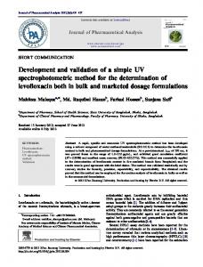
1. INTRODUCTION All components of solar systems exposed to the sun are usually subjected to UV-radiation. The intensity of the UVirradiation depends on the local climate, of course, but is typically around 5.5% of the global solar irradiation. The effect on the material is very different. Most sensitive are organic materials like eyes, skin, paint coatings, polymers etc.. The degradation processes in these materials depend on their spectral sensitivity. Usually the high-energy radiation at shorter wavelengths causes more damage and often a minimum energy is needed for destroying the molecular bonds in these materials. Therefore, the spectral distribution of the irradiation is of high importance and a restriction on integral UVdata is not really sufficient. On the other hand, testing with unrealistic high UV-energies (UV-C, e.g.) will lead to erroneous results. Nevertheless it is helpful to consider the integral UV-irradiation at different sites in order to figure out the worst-case conditions. There are a lot of monitored data from UV-networks around the world, but we need to get the data correlated with the sample temperature, since the temperature accelerates the photo-degradation processes, not only during operation but also during testing. Figure 1 shows the total UV-dose as function of the module-temperature for one year exposure and monitoring in 5min intervals. It turned out that the integral UV-sensors at the 3 sites except of the desert Reliability of Photovoltaic Cells, Modules, Components, and Systems II, edited by Neelkanth G. Dhere, John H. Wohlgemuth, Dan T. Ton, Proc. of SPIE Vol. 7412, 741202 · © 2009 SPIE · CCC code: 0277-786X/09/$18 · doi: 10.1117/12.825939 Proc. of SPIE Vol. 7412 741202-1
were badly calibrated and need calibration for correction of the data, but that would only change the dose, but not the shape of the distribution functions.
total UV dose per temp.-interval [Wh/m²]
6000
5000
4000
tropics desert city alps
3000
2000
1000
0 -20
-10
0
10
20
30
40
50
60
70
mean module temperature [°C]
Figure 1: Total UV-dose as function of the module-temperature for one year exposure and monitoring in 5min intervals at 4 different climatic conditions
equivalent testing times for five suns UV test from desert climate loads 10000
60 °C 70 °C 80 °C 90 °C
log testing time [h]
1000
100
10
1 20
50
100
150
200
250
300
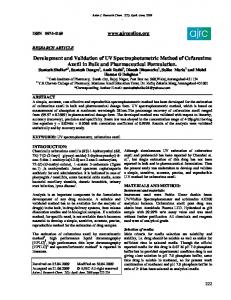
activation energy [kJ/mol] Figure 2: Resulting testing time for the desert conditions is given as function of the activation energy E for different test temperatures
The UV-preconditioning test in the presently updated type-approval testing standards IEC 61215 and IEC 61646 requires a total UV irradiation of 15 kWh/m² in the wavelength range between 280 nm and 400 nm, with 3 % to 10 % of the total
Proc. of SPIE Vol. 7412 741202-2
energy within the wavelength band between 280 nm and 320 nm. It does not reflect the real UV-exposure at all, which was measured to be 120 kW/m² for the one year in the desert. The standard IEC 61345 limits the intensity for UV-test devices to 5X of the natural sunlight. The temperature effect on the acceleration of the degradation can be taken into account by using the most common model for accelerated aging:
ΔPi = A In Δti exp[-E /RT] With the degradation process depending parameters A, n, E, the gas-constant R, and the UV irradiation I at the sample temperature T leading to a change ΔPi of the sample property P after the time-period Δti. The outdoor data need to be integrated. We assumed n=1 and considered the simulation of the service life of 25years at constant accelerated test conditions (the parameter A is than not relevant). The resulting testing time for the desert conditions is given as function of the activation energy E for different test temperatures in Figure 2. It is clear that processes with relatively low activation energies cannot be accelerated very much by increasing the temperature during irradiation. But on the other hand, enhancing the temperature the standard test conditions from actually 60°C to 90°C sample temperature would accelerate the tests by a factor of clearly more than 10, or would allow testing at a higher, more realistic UV-dose.
2. THE UV-SOURCE Indoor-testing with irradiation on device level is not very popular, because a large area (high investment) with high irradiation (high costs for energy and consumables like lamps) would be needed. But there is no other way for guaranteeing the reliability of solar components, which are more and more composed of polymers, since the outdoor exposure requires much more time and can just be used for validating indoor testing. The light-source should be ideally as close to the natural solar spectrum as possible, but with a higher intensity. The most solar-like source is actually a filtered Xenon-arc. The main disadvantage is the heat load for the sample by the visual and near-infrared part of the radiation, especially when the UV-intensity should be enhanced. It would not be possible to keep the PV-module temperature below 100°C with practical measures in this case. Therefore we choose the fluorescent lamp with the 340 phosphor as appropriate light source, because the contribution in the VIS-NIR range is small and the UV is not too much affected by narrow-banded emission-lines (see figure 3). There was no supplier for long fluorescent 340 lamps.
440
irradiation in µW/m²nm
400
old UV-unit new UV-unit
360 320
UVA: 233,47 W/m² UVB: 12,01 W/m² UV tot: 245,5 Wm² UVB in %: 4,8
280 240 200 160 120 80 40 0 280
320
360
400
440
480
520
560
600
Wavelength in nm
Proc. of SPIE Vol. 7412 741202-3
Figure 3: Spectral distribution of different set-ups with fluorescent UV light-sources. The red line is the spectrum of the newly developed source.
1,00 0,95
rel. Transmission
0,90 0,85
new 1000h D/H uncleaned 1000h D/H cleaned 4mm Solar glass
0,80 0,75 0,70 0,65 0,60 0,55 0,50 0,30
0,35
0,40
0,45
0,50
0,55
0,60
0,65
0,70
0,75
0,80
Wavelength in µm
Figure 4: Spectral transmission of soda lime glass used for fluorescent UV light-sources and solar-glass for comparison. The red line is the transmission spectrum after 1000h damp-heat testing, the green-one after cleaning.
Therefore, a German company (Narwa) started to manufacture 2m tubes of soda-lime glass coated with this phosphor. Before that, we investigated the durability of soda-lime glass in humid environment, because we intended to use the light-source for combined testing of humidity and UV. Figure 4 shows the effect of damp-heat testing at 85% and 85°C on the transmission of the soda-lime-glass. The observed reduction was caused by loose degradation products on the glass surface, which could be removed by cleaning in de-ionised water.
110
normalised UV-irradiation
100 90 80 70 60 50 40 30 20 0
10
20
30
40
50
60
70
80
90
100
Temperature in °C
Figure 5: Intensity of the fluorescent UV light-sources as function of the temperature of the tubes.
Proc. of SPIE Vol. 7412 741202-4
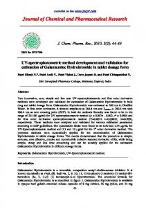
The temperature dependence of the emission of the UV has to be taken into account for the optimisation of the intensity of the fluorescent lamps (see figure 5). The lamps have to be cooled down below 40°C at some part in order to keep the circular mercury process running. We set up a partial water-cooling of the tubes, which helps to reduce the cooling load in the climatic chamber in addition. Finally an optimised design of the tubes was constructed and suitable power supplies selected for a 120 tubes UV-source with an energy consumption of 200W each, covering an area of two times 3m * 1.8 m (see figure 6). The maximum UVpower is 233 kW/m² (see figure 3).
Figure 6: The light-source in operation in a climatic chamber
3. RESULTS The effect of stronger UV-exposure is presently studied by exposing 6 different commercially available full-scale PVmodules based on crystalline silicon cells. All encapsulants were EVA. The ambient temperature in the cabinet was 60°C. The UV-radiation heated the modules to 90°C. After exposure up to 150 kW/m², which is 10 times the dose required for the UV-preconditioning tests, but applied at 90°C module temperature, no drastic changes of the peak-power of the modules could be found (see figure 7). But some modules seem to degrade continuously and it would be interesting to continue the UV-testing until the maximum dose expected for 25 years service might be reached and to apply service life modelling according to figure 2.
Proc. of SPIE Vol. 7412 741202-5
Dry UV-testing 1,05
Normalised power
1,00
1 2 3 4 5 6
0,95
0,90
0,85
0,80 -20
0
20
40
60
80
100
120
140
160
180
200
UV dose kWh/m²
Figure 7: Relative changes of the module power at mpp during dry UV-exposure at 90°C sample temperature.
Combined UV and humidity (58%@60°C) 1,05
Normalised power
1,00
1 2 3 4 5 6
0,95
0,90
0,85
0,80 -20
0
20
40
60
80
100
120
140
160
180
200
UV dose in kWh/m²
Figure 8: Relative changes of the module power at mpp during UV-exposure at 60% rel. humidity and 80°C sample temperature.
The combination with humidity is limited by the cooling power needed for dumping the energy introduced by the UVsource (up to 24 kW). A maximum of 60% relative humidity was reached at 60°C ambient temperature in the cabinet and 80°C sample temperature at 112 W/m² UV-radiation. The changes seem to be stronger than at dry UV-exposure. We do not expect a uniform water-concentration in the encapsulants according to FEM-simulation of the water diffusion in PVmodules, which resulted in estimated testing times of more than 2000h at 85%rh and 86°C for a kind of equilibrium of the water concentration in the encapsulant [1]. Therefore a longer exposure for combined testing or a kind of preconditioning damp-heat-test would be required.
Proc. of SPIE Vol. 7412 741202-6
4. CONCLUSION Solar installations in Central Europe have shown only low power loss after 20 years operation and nearly no optical degradation. On the other hand modules in southern Europe, tropical locations and in the dessert often have shown browning and significant power loss after 10 years. The described UV equipment is able to provide UV-radiation up to 5 times the solar radiation on both sides with uniformity much better than required by IEC 61215 and very low visible and NIR irradiation for large sample areas, reducing the thermal load to the samples. The height is limited to 1.8m, but the length could be adapted to the desired set-up. The UV-source allows accelerated lab testing at higher irradiation, at elevated, well controlled temperature and humidity.
5. ACKNOWLEDGEMENTS The authors wish to thank Peter Trubiroha for his extremely fruitful consultancy during the evaluation of the lightsources and Stefan Brachmann and Claudio Ferrara for the qualification of the power supplies. The work was partly funded by the German Federal Ministry for the Environment, Nature Conservation and Nuclear Safety (BMU FKz 0329978) and sponsored by the industrial partners Scheuten Solar, Schott Solar, Solarfabrik, Solarwatt, Solar World and Solon.
REFERENCES [1]
Köhl, M. et al., Internal reports: Zuverlässigkeit von PV-Modulen, Fraunhofer ISE, (2006 – 2009).
Proc. of SPIE Vol. 7412 741202-7