Development and Verification of the SIMMER-III Code for Molten Salt Reactors
Shisheng Wang, Andrei Rineiski, and Werner Maschek Forschungszentrum Karlsruhe Institute for Nuclear and Energy Technologies Postfach 3640, D-76021 Karlsruhe, Germany
[email protected]
Abstract – Molten Salt Reactors (MSR) combined with on-site fuel reprocessing (on-line or batch wise) can be charged with a variety of additives in the liquid fuel such as plutonium (Pu), minor actinides (MAs) and long lived fission products and are suited for transmutation and burning such materials safely [1]. The motion of liquid molten salt fuel in core and external circuit introduces unique phenomena which differ from solid fuel reactors in thermo-hydraulic and delayed neutron precursor aspects. An extension of the SIMMER-III code, which has been initially developed for solid fuel reactors [2], modelling the motion of the liquid fuel through the core and outside in the external circuit is presented in this paper. In addition the results of two benchmark activities are given. I. INTRODUCTION Molten salt reactors were first proposed by ORNL in the later 1940’s attempting to design a nuclear-powered aircraft − the Aircraft Reactor Experiment (ARE), a 2.5MW(th) reactor operated successfully in 1954 at temperature up to 860°C. A further molten salt reactor experiment (MSRE) was built and operated successfully at a power level of 7.3 MW(th) until end of 1969 following the ARE at ORNL[3]. Those experiments demonstrated well that the molten salt reactors were extremely flexible. The same design can handle a variety of fissile materials and additives in the liquid fuel such as spent fuel, plutonium, Minor Actinides (MAs) and long lived fission products and can readily be adapted to transmutation and burning of nuclear waste. Investigations on the incineration and transmutation of Minor Actinides (MAs) by different reactor concepts are underway in Europe. Currently molten salt reactors for transmutation are investigated within the 5th Framework Programme MOST of European Union [4]. The fuel of this reactor is liquid in the form of a molten salt mixture, which also acts as a coolant at the same time [5]. The liquid fuel circulates from the core through the primary external loop to a primary heat exchanger and again into the core. The delayed neutron precursors are redistributed in the core contrary to solid fuel reactors because of the movement of the liquid fuel, furthermore, a portion of the delayed neutron is emitted outside of the core. As a consequence, the delayed neutrons play a significant role and can have important effects on the dynamic response of the systems. To perform this type of molten salt reactor
analyses, the safety analysis code SIMMER-III had to be extended both in its neutronics and thermo-hydraulics parts. An overview of the development of the SIMMERIII code for modelling molten salt reactors is presented. In addition the results of two benchmark activities are given to verify the code. II. SIMMER-III CODE EXTENSION FOR MOLTEN SALT REACTOR ANALYSES SIMMER-III is a two-dimensional, three velocity field, multi-phase, multi-component, Eulerian fluiddynamics code coupled with a structure model and a space-, time and energy-dependent neutron dynamics model. In total, 46 conservation equations for fluiddynamics (27 mass, 16 energy and 3 momentum) are solved. The numerics of the fluid dynamics model utilizes a 2nd order difference scheme in space and time. The key advantage of SIMMER-III compared to other code is its potential to model phase transitions, particle formation, separation, etc. within its framework. Another feature is the tracking of interfacial areas with their respective sources and sinks [2], [6]. In neutronics, the transient neutron flux distribution is calculated with the improved quasi-static method [7]. For the space dependent part, a TWODANT-based flux shape calculation scheme has been implemented [8]. So far, this code have been used to safety analysis of reactors with solid fuels, [9-11]. As mentioned above, the essential feature of molten salt reactors is the liquid fuel circulating in the core region and in the external loop. SIMMER-III must be extended
to simulate the related neutronics, the specifics of the core region and external loop. II. A. Extension of Neutron Model The neutronics part of SIMMER-III includes (1) a cross section generator, (2) a multi-dimensional neutron transport module, and (3) a neutron kinetics model based on the improved quasi-static scheme [7]. Currently, we (1) extend available nuclear data libraries and a refine the cross section treatment to take into account properly major reactivity feedbacks, (2) optimize neutron transport calculations to accelerate them, and (3) extend the kinetics model to simulate the effect of delayed neutron precursor movement. At nominal conditions, a part of the precursor nuclei does decay outside the core (in the loop) producing the delayed neutrons. Therefore the effective fraction of the delayed neutrons existing in the core is smaller compared to the same system with non-movable fuel, while the reactivity is greater (i.e. it is positive) to meet the reactivity balance. If the fuel circulation is stopped, this excess of reactivity may induce a power increase in case e.g. control rods are not moved into the core. For this reason, that a part of delayed neutrons are released in the external loop, a new model for the delayed neutron precursor movement is developed. The equations describing this movement and redistributions of the precursors are:
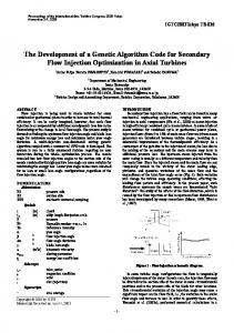
The main purpose of loop model is to simulate the behavior of pump and intermediate heat exchanger. The loop model (see Fig. 1) is one-dimensional, the inlet and outlet boundary cells of SIMMMER-III serve as outlet and inlet boundary cells of the loop model, respectively. Mass flow rate is chosen as independent variable in this model. Inlet and outlet boundary cells of the loop model are connected with the Bernoulli equation. The one dimensional energy transport equation of molten salt in the loop is described with the Euler method, with a Dirichlet boundary condition at loop inlet and a convective boundary condition at loop outlet. There dose exit a 3D version of SIMMER, SIMMER-IV, where the external loop could be directly modeled. But it is very time-consuming. For this reason, the 2D SIMMER-III is extended to simulate molten salt reactors with an extension of a loop module, Fig. 1.
1-1 Q
SIMMER III (Core+vessel)
In the core, G ∂Ci ( x,t ) ∂(V ( x,t )Ci ( x,t )) (1) = N β Fψ ( x,t0 ) − λCi ( x,t ) − ∂t ∂x
2-2
P
LOOP
z
and in the external loop, G ∂Ci ( x,t ) ∂(V ( x,t )Ci ( x,t )) , = −λCi ( x,t ) − ∂t ∂x
PUMP
(2)
where i=1,6 stands for the i-th group of the precursors. The movement is modelled in the core and loop as above, the basic assumption being that variations of precursor concentrations - caused by their movement affects the flux amplitude much stronger than the shape. Therefore, the traditional flux factorization (the flux is the product of the shape and amplitude, the shape is computed relatively seldom compared to the amplitude) still can be employed to improve the code efficiency, but no factorization is performed for the precursors. Instead, we simulate spatial precursor movement for a fine (amplitude) time mesh and then compute effective precursor fractions (needed for the amplitude calculations) by weighting them with neutron importance. II. B. Extension of the Thermo- & Fluid Dynamics Part
x (r) Fig.1 SIMMER-III coupled with loop model II. C. Equation of States: Adaptation to Molten Salt In SIMMER-III, equation of states (EOSs) of the basic reactor core materials such as solid fuel, steel and various coolants are calculated by an analytic EOS model. The EOS function forms are designed in a very flexible way. For molten salt reactors, the salt is a type of fluoride salt. The fluoride salt consist of LiF und BeF2, which are homogenous mixtures with fluoride fissile materials. For the application with SIMMER-III, EOS data of such molten salt have to be evaluated over a wide temperature range from the liquid to supercritical state. The SIMMER-
III formulism with analytical EOS functions requires this elaborate work. The database for such salts is rather scarce especially in the high temperature range and the EOS must be based on available experimental data and thermodynamic theory. For getting started and for adapting and testing available codes, salt data of the following type have been chosen: A homogeneous salt mixture of 71.7%LiF + 16%BeF2 + 12%ThF4 + 0.3%UF4 (mole percents). For pure materials, the variation of vapour pressure with temperature can be represented by the well-known equation:
log10 p = a − b / T
(3)
From available database of the MOST programme salt components, we can get the coefficients a and b using Eq. (3) for LiF, BeF2, ThF4 and UF4, respectively. Subsequently, the Dalton model has been used to approximate the mixture pressure of this type of molten salt. Pmix=0.717*PLiF+0.16*PBeF2+0.12*PThF4+0.003*PUF4 (4)
3.9624
3*0.20 0.60
As mentioned before, for a complete characteristic of the EOS in SIMMER-III, material data have to be provided up to the critical point. A method proposed by Watson is applicable to a large class of non-polar and some slightly polar components, [12]. With this method we get the critical temperature of salt. Thermo-physical properties such like viscosity, surface tension, thermal conductivity etc. are determined from available experimental information or extrapolated to the required
Core
Salt volume:13% 0.5868
2.59845
0.60
3*0.20
(Dimensions in m)
0.6096
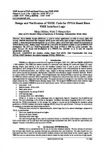
Fig. 2. Sectional view of molten salt reactor
Fig. 3.Core element of molten salt reactor, graphite in grey temperature range. III. CALCULATIONAL RESULTS AND DISCUSSIONS The first Benchmark simulation with the extended 2D SIMMER-III code concentrates on the performance features of a single-fluid molten salt benchmark reactor based on the Molten Salt Breeder Reactor (MSBR) project, (see. [3, 13, 14] and Fig.2, Fig.3). The power is 2250 MW(th), the core height accounts for ~3.96m, and ~5.20m in diameter. This core consists of extruded graphite elements, 0.10m × 0.10m × 3.96m long. A 0.0127m diameter hole through the centre of every core element, and ridges on each side of the elements to separate the pieces, furnish flow passages and provide the requisite 13% salt volume in this portion of the reactor, see Fig. 3. Outside of the core there is a ~0.60m thick layer of radial reflector graphite, at the top and bottom there are also graphite reflectors, as indicated in Fig. 2. In the SIMMER-III simulation the mesh points are 16 × 35 in radial and axial directions in a 2D cylindrical coordinate respectively, accordingly, the neutronics mesh is 40 × 45. The molten salt enters the bottom of the reactor at ~565°C and leaves the core at top at ~701.4°C, which reproduces the given benchmark conditions, see table I. TABLE I. Comparison of MSBR Plant Data and SIMMER-III Calculated Values Plant Date SIMMER-III MS Fuel Flow Rate (Kg/s) 12263.4 12220.5 Inlet Temperature (°C) 565 565 Outlet Temperature (°C) 704 701.4 Fuel Density at Outlet 3285 3316 Temperature (Kg/m3) Average Fuel Velocity in 0.92 0.90 Core Region (m/s) Velocity Distribution Core 2.44~0.61 2.33~0.54 Inlet Cross Section (m/s)
highest and designed salt temperature. The salt leaves the top plenum radially.
[m]
[m/s]
[K]
Fig. 4. Velocity distribution in core inlet cross section [m]
Fig. 4 shows the calculated average velocity distribution in the core inlet cross section (mesh number 3 in axial direction of Fig.5) and Fig. 5 shows the calculated 2D velocity vector distribution in the core region. The calculated salt axial velocity reaches 2.33m/s at the core centre and decreases monotonously to 0.54m/s near the core periphery (mesh number 11 in radial direction in Fig. 5). The designed velocity range of MSBR is from 2.44m/s to 0.61m/s, see Table I. Around the active core, there is a bypass of molten salt, in which the volume fraction of salt accounts for ~37%, to serve to reduce the radial neutron leakage. In this bypass region the liquid salt axial velocity increases gradually to 1.47m/s along radial direction (from mesh number 12 to 14 in radial direction in Fig. 5).
Fig. 6. 2D salt temperature distribution in core region Another Benchmark activity is the transient calculation for zero-power Molten Salt Reactor Experiment (MSRE) for fuel pump start-up and coastdown to verify the extended neutron model: Eq. (1) and (2), see [15]. The experimental results and the calculated transient are presented in Fig. 7. The figure shows the control rod withdrawal from and insert into the core to maintain the system criticality. Comparison to the Experiment SIMMER-III gives satisfactory results.
[m/s]
21
modeling:pump up experiment:pump up modeling:pump down experiment: pump down
Control Rod position (in)
20 19 18 17 16 15 14
Fig. 5. 2D Velocity distribution in core region Fig. 6 shows the calculated 2D temperature distribution of the molten salt reactor (MSBR). The molten salt temperature rises across the core is quasiuniform until top plenum. Here the salt reaches the
0
10
20
30 40 Time (s)
50
60
70
Fig. 7. Pump start-up and coast-down transient of MSRE
IV. CONCLUSIONS The SIMMER-III neutronics, thermo-hydraulics and equation of state (EOS) have been extended for molten salt reactor application. The neutronics model is ready to model the effect of the delayed neutron precursor movement. A thermo-hydraulic loop module has been implemented in SIMMER-III for describing the external primary loop. Finally a complete equation of state (EOS) for the 71.7%LiF + 16%BeF2 + 12%ThF4 + 0.3%UF4 (mole presents) molten salt has been developed. Two benchmarks based on the MSBR and MSRE have been recalculated. The results of the simulation show that the extended SIMMER-III can be well applied for molten salt simulation. ACKNOWLEDGMENTS This work has been funded by the EU Program MOST, contract No: FIKW-CT-2001-00096. REFERENCES 1.
2. 3. 4.
5.
6. 7. 8.
9.
U. GAT, Safe Actinide Disposition in Molten Salt Reactors, Proceedings of the international topic meetings on advanced reactors safety, Vol. 1, pp.74~77, Orlando, Florida, June 1-5, (1997). SA. KONDO, et al, SIMMER-III, A Computer Program for LMFR Core Disruptive Accident Analysis, JNC TN9400 2000-002 (2000). A.M. Weinberg, et. al.: Collection of Papers on the Molten Salt Reactor Experiment, Nuc. Appl. Technol. Vol. 8, (1970). MOST PROJECT, Review and Revaluation of Molten Salt Reactor Technology and Previous Realisations or Projects, 5th Framework Programme of European Commission, (2001). M.V. ROSENTHAL, et al, Advances in the Development of MSBR, Proceedings of the Fourth International Conference on the Peaceful Uses of Atomic Energy, A/Conf. 49/P048, Geneva, (1971). Sa. Kondo et al., “Current Status and Validation of the SIMMER-III LMFR Safety Analysis Code,” Proc. ICONE-7, Tokyo, Japan (1999). K. O. Otto and R. J. Neuhold, Nuclear Reactor Dynamics, ANS, La Grange Park, USA (1986). G. Buckel, E. Hesselschwerdt, E. Kiefhaber, S. Kleinheins and W. Maschek, “A New SIMMER-III Version with improved Neutronics Solution Algorithms,” FZKA 6290, Karlsruhe, Germany (1999). W. Maschek et. al.: Safety Analyses for ADS Cores with Dedicated Fuel and Proposals for Safety Improvements, IAEA TCM 2000, Argonne, USA, (2000).
10. W. Maschek et. al.: SIMMER-III Code Development for Analyzing Transients and Accidents in Accelerator Driven Systems, AccApp’00. Washington, USA, (2000). 11. X.-N. Chen. T. Suzuki, A. Rineiski, E. Wiegner, W. Maschek and M. Flad, “Unprotected Transients in a Small Scale Accelerator Driven System,” Proc. AccApp’03, US (2003). 12. T.C. Chawla et. al.: Thermophysical Properties of Mixed Oxide Fuel and Stainless Steel Type 316 for Use in Transition Phase Analysis, Nuclear Engineering & Design, vol. 67 pp.57~74, (1981). 13. E.S. Bettis and R.C. Robertson: The Design and Performance Features of A Single-Fluid Molten Salt Breeder Reactor, Nuclear Application & Technology, Vol. 8, (1970). 14. H.G. MacPherson: The Molten Salt Reactor Adventure, Nuclear Science & Engineering, Vol. 90, pp.374~380, (1985). 15. B.E. PRINCE, et al., Zero Power Physics Experiments on the Molten Salt Reactor Experiment, ORNL-4233, (1968).