Research Report
2007-29
Simulation of a High Temperature Superconducting Synchronous Machine with Stator Core Saturation
T.A. Lipo Dept. of Elect. & Comp. Engr. University of Wisconsin-Madison 1415 Engineering Drive Madison, WI 53706
University of Wisconsin-Madison College of Engineering Wisconsin Power Electronics Research Center 2559D Engineering Hall 1415 Engineering Drive Madison WI 53706-1691 © 2007 Confidential
Simulation of a High Temperature Superconducting Synchronous Machine with Stator Core Saturation T.A. Lipo University of Wisconsin Madison WI USA Phone (608)262-0287, Fax (608)262-5559, E-Mail
[email protected], WWW http://www.wempec.org/users/lipo Abstract - Saturation effects in salient pole synchronous machines are generally modelled by assuming that the saturation effect is primarily limited to the field pole. However, a superconducting machine does not possess field pole saturation since it is free of iron. The stator, however, remains surrounded by an iron shell so that saturation of the stator core is possible. This paper addresses the modeling and simulation of the stator of a superconducting synchronous machine taking into account the correct components of flux linkage which contribute to this effect. Suitable saturation curves are computed using finite element methods. Simulation results are shown using the new saturation model.
these effects. Suitable saturation curves are computed using finite element methods. Simulation results are shown and compared to models with simple rotor saturation models showing the difference in predicting terminal behavior.HSTC Machine Development
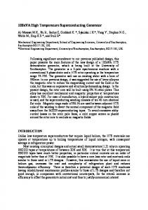
I. INTRODUCTION Development of high temperature superconducting (HTS) machines is proceeding rapidly worldwide. HTS machines offer the advantages of smaller size, lighter weight, better efficiency and lower noise compare to conventional AC machines. The initial use for HTS motors will likely be in transportation applications, particularly naval and commercial ship (marine) electric propulsion, where critical size and weight savings will provide a key benefit by increasing ship design flexibility. In particular, the U.S. Navy is in the midst of developing two such machines rated at 5MW and 25 MW. A sketch of the 5 MW machine is shown in Figure 1. Both machines are presently in the process of validation testing. Superconducting machines differ dramatically in their geometry compared to conventional synchronous machines so that their proper modeling requires modification of the conventional Park’s d–q model. In particular, saturation effects in salient pole synchronous machines are typically modeled by assuming that the saturation effect is primarily limited to the field pole and the effect is, hence, a function of the field flux linkages. However, the two high temperature superconducting (HTS) machines manufactured by Alsthom and Superconductivity Inc. [1] does not posses field pole saturation due the absence of magnetic material on the rotating member. However, a different situation occurs in a HTS synchronous machine in which the core surrounding the stator windings can saturate. The saturation effect of the stator cannot be simply lumped with the field pole saturation since stator core saturation is the vector sum of d– and q–axis stator flux linkages while the field pole is essentially dependant only on d–axis flux linkage components. This paper addresses the modeling and simulation of saturation of the stator core of a HTS synchronous machine taking into account the correct components of flux linkage which contribute to
Figure 1 HTS synchronous machines under development by the U.S. Navy [2].
II. HSTC MACHINE DEVELOPMENT Superconducting wire in its Low Temperature Superconductor (LTS) form has been in widespread use now for over 30 years, and commercial applications today range from high-powered particle accelerators to sensitive resonance imaging systems utilized for medical diagnostics. General Electric and Westinghouse independently conducted large superconducting generator design studies during the 1970's based on LTS wire made up of a niobium-titanium (NbTi) alloy. General Electric also built and tested a 20 MVA superconducting generator in the 1970's, and a Japanese consortium built and tested a 70 MW generator during the 1990's. However, even at such large ratings, the complexity and cost of the refrigeration equipment, and the challenging nature of thermal isolation systems that are necessary for allowing LTS materials to operate at an ultralow 4K, has prohibited widespread application.
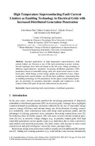
However, advances in the development of HTS wire over the past 15 years have resulted in superconducting electromagnets that can operate at substantially higher temperatures than those made of LTS materials, and which as a consequence can utilize relatively simpler, less costly, and more efficient refrigeration systems. These factors make HTS wire technically suitable and economically feasible for use in the development and commercialization of motor and generator applications at power ratings much lower than could be considered with LTS wire. American Superconductor Corporation (AMSC) has developed a design for a 5 MW HTS model motor for ship propulsion; this motor demonstrates technologies to be employed in a full-size 25 MW, 120 RPM HTS motor. AMSC has also developed a conceptual design for a 50 MW, 3600-RPM HTS generator. Other companies are also developing Super Machines. A 1000 hp, 1800-RPM motor funded under the SPI program, and built by a team consisting of Rockwell Automation, AMSC, and others, was successfully operated in May 2000. Siemens demonstrated a 550 hp, 1800-RPM motor in the summer of 2001. The major components of a rotating machine employing a HTS winding is shown in Figure 2. Only the field winding employs HTS cooled with a cryocooler subsystem to about 35-40K. The cryocooler modules are located in a stationary frame and a gas, such as helium, is employed to cool components on the rotor. The stator winding employs conventional copper winding but with a few differences. The stator winding is not housed in conventional iron core teeth because they saturate due to high magnetic field imposed by the HTS winding. However the stator is enclosed with a back iron shield which is used to contain the flux within the machine. Thus the machine remains capable of saturating under high flux conditions but the flux component which contributes to this saturation clearly involves the total stator flux (including the air gap portion of the stator leakage flux) and not the simply the field flux.
magnetizing inductances respectively. In Figure 1 the stator leakage inductance typically expressed a Lls has been separated into two portions namely Lles and Llcs to denote the leakage inductances which correspond to the end winding and the core portions of the leakage flux linkages respectively. The two portions of the stator leakage inductances have been separated since saturation of the stator core only involves that portion of the stator leakage flux which passes through the stator core. The equations corresponding to the circuit of Figure 1 are, dλ qs v qs = r s i qs + ------------ + ω r λ ds . dt
(1)
dλ ds v ds = r s i ds + ------------ – ω r λ qs dt
(2)
dλ qr v qr = r qr iqr + -----------dt
(3)
dλ dr v dr = r dr idr + -----------dt
(4)
dλfr v fr = r fr i fr + ---------dt
(5)
For purposes of simulation Eq. 5 is usually manipulated to the form ω b L md dλ fr e x = ω b L md i + ----------------- ---------fr r dt
(6)
fr
where e x = ω b ( Lmd ⁄ r fr )v fr and ω b is a selected base frequency. The amortisseur voltages vqr and vdr are zero except for special cases. The flux linkages in Eqs. 1-5 are defined by referring to Figure 2. They are,
Back Iron Stator Coils Stator Support Tube Output Shaft
Housing Support Structure Rotor Coils
Figure 2 Schematic diagram of a high temperature superconducting synchronous machine [2].
III.
D-Q REPRESENTATION OF A HTS
SYNCHRONOUS MACHINE
Park’s model of a salient-pole synchronous machine, represented in the rotor reference frame, is shown in Figure 1. The quantities rs, rdr, rqr and rfr correspond to the stator, d– axis rotor amortisseur, q–axis amortisseur and field winding resistance all referred to the stator by the appropriate turns ratio. The quantities Lmd and Lmq are the d– and q– axes
λ qs = L les i qs + λ qcs
(7)
λ ds = L les i ds + λ dcs
(8)
λ qr = L lqr i qr + λ mq
(9)
λ dr = L ldr i dr + λ md
(10)
λ fr = L lfr i fr + λ md
(11)
and λ mq = L mq ( iqs + iqr )
(12)
λ md = L md ( ids + idr + i fr )
(13)
λ qcs = L lcs iqs + λ mq
(14)
λ dcs = L lcs ids + λ md
(15)
The electromechanical torque produced by the machine is typically expressed as [1] 3 P T e = ⎛ ---⎞ ⎛ ---⎞ ( λ ds i qs – λ qs ids ) ⎝ 2⎠ ⎝ 2 ⎠
(16)
IV. SIMULATION OF A SYNCHRONOUS MACHINE USING FLUX LINKAGES AS VARIABLES Since the differential equations of the machines, Eqs. (1)(5), contain mixed variables either flux linkages or currents could be eliminated from the differential equations by means of the algebraic relations, Eqs. (7)–(15). Modelling of saturation is best achieved by retaining flux linkages as the state variables. The current can be solved in terms of the flux linkages as,
Figure 3 d-q axis equivalent circuit of a salient pole synchronous machine where the stator leakage inductance has been separated into saturable (core) and non-saturable (end winding) portions.
λ qs – λ qcs iqs = -------------------------L les
(18)
λ ds – λ dcs ids = -------------------------L les
(19)
λ qr – λ mq iqr = ------------------------L lqr
(20)
λ dr – λ md idr = ------------------------L ldr
(21)
λ fr – λ md ifr = ----------------------L lfr
(22)
Eliminating λ md and λ mq from Eqs. (18)–(20) using Eq. (14) and (15) and substituting the result into Eqs. (20)–(22), L lcs L ls ⎞ 1 ⎛ i qr = ---------- ⎜ λ qr + ---------- λ qs – ---------- λ qcs⎟ L les L les L lqr ⎝ ⎠
(23)
L lcs L ls ⎞ 1 ⎛ i dr = ---------- ⎜ λ dr + ---------- λ ds – ---------- λ dcs⎟ L les L les L ldr ⎝ ⎠
(24)
L lcs L ls ⎞ 1 ⎛ i fr = --------- ⎜ λ fr + ---------- λds – ---------- λ dcs⎟ L les L les L lfr ⎝ ⎠
(25)
where L ls = L lcs + L les
(26)
The internal stator core flux linkages λ dcs and λ qcs can now be written in terms of the total stator and rotor flux linkages as Figure 4 Flux linkages used as state variables.
Finally, since the machine is generally tied to an external load/prime mover, in its simplest form the equation which describes coupling between the electrical and mechanical system can be written as 2 dω r T e – T load = ⎛ ---⎞ J --------⎝ P⎠ dt
(17)
where Tload is the load torque (negative if the “load” corresponds to a prime mover torque) and J is combined inertia of the machine and load.
L∗dcs L∗dcs L∗dcs λ dcs = --------------λ ds + -------------- λ dr + -------------- λfr L ldr L lfr L∗lds L∗qcs L∗qcs λ qcs = -------------- λ qs + -------------- λ qr ∗ L lqr L lqs
(27) (28)
where 1 L∗dcs = --------------------------------------------------------------------------L ls 1 1 1 1 -------- ⎛ ---------- + ---------- + ---------⎞ + ---------L es ⎝ L md L ldr L lfr⎠ L les
(29)
1 L∗qcs = ----------------------------------------------------------L ls 1 1 1 -------- ⎛ ---------- + ----------⎞ + ---------L es ⎝ L mq L lqr⎠ L les 1 L∗lds = ----------------------------------------------------------------------------L lcs 1 1 1 1 ---------- ⎛ ---------- + ---------- + ---------⎞ + ---------L les ⎝ L md L ldr L lfr⎠ L les 1 L∗lqs = ------------------------------------------------------------L lcs 1 1 1 ---------- ⎛ ---------- + ----------⎞ + ---------L ⎝L L ⎠ L les
mq
lqr
(30) vqs
λ (31)
ds
1/p x
λ qs
(Eq. 31)
iqs (Eq. 18)
λ
λ
(32)
qcs
(Eq. 14)
iqr
les
These results can be inserted into the differential equations described by the circuit of Figure 5. Upon solving for the time derivative terms and integrating, the result is,
ω
(Eq. 20)
r 1/p
λ qr
(Eq. 35)
λ qs = λ ds =
∫ ∫
rs v qs + ------- ( λ – λ qs ) – ω r λ ds dt L les qcs rs v ds + ------- ( λ – λ ds ) + ω r λ qs dt L les dcs
(33) (34)
r qr L ls L lcs⎞ ⎞ ⎫ ⎧ λ qr = ∫ ⎨ v qr + ---------------λ qcs – ⎛ λ qr + ⎛ ------- λ dt ⎝ ⎝ L L L les⎠ qs⎠ ⎬⎭ lqr les ⎩
(35)
r dr L ls L lcs⎞ ⎞ ⎫ ⎧ λ dr = ∫ ⎨ v dr + ---------------λ dcs – ⎛ λ dr + ⎛ ------- λ dt ⎝ ⎝ L L L les⎠ ds⎠ ⎬⎭ ldr les ⎩
(36)
r fr ⎧ L md L ls L lcs⎞ ⎞ ⎫ λ fr = ∫ -------------- e + ω b ------- -------- λ – ⎛ λ + ⎛ ------- λ dt ω b L md ⎨⎩ x Ll fr L les dcs ⎝ fr ⎝ L les⎠ ds⎠ ⎬⎭
(37)
P 1 ω r = ⎛ ---⎞ ⎛ ---⎞ ∫ ( T e – T load ) dt ⎝ 2 ⎠ ⎝ J⎠
vds
λqs
1/p
Figure 5 x
λ ds
λqs iqs λ ds ids
Te
ω
(Eq. 16)
1/p
r
(Eq. 17)
Tload
(Eq. 34)
ids (Eq. 19)
λ (Eq. 15)
dcs idr (Eq. 21)
1/p
(38)
λ
dr
(Eq. 36)
The flow of signals for simulation of a salient pole synchronous machine is shown in Figure 5. V. MODELING OF SATURATION In conventional cases saturation can be taken into account accurately by expressing the air gap flux linkage as a nonlinear function of the air gap MMF. While the air gap MMF is difficult to determine under a loaded condition, the required relationship can be established of the motor is operated under an open circuit in which case the MMF is clearly proportional only to field current since the stator current is, in this case, zero. If the open circuit voltage is plotted versus the field current the saturation curve of Figure 6(a) can be established. The slope of a line drawn from the origin to a point on the straight line (unsaturated) portion of the curve is equal to the stator d–axis mutual reactance. If the abscissa of Figure 6(a) is multiplied by the d–axis mutual reactance and the ordinate by 1 ⁄ ω r , the normalized curve of Figure 6(b) results in which the abscissa remains proportional to MMF while having the units of webers. The slope of the unsaturated portion of the curve is now clearly unity. The difference between the saturated and unsaturated values of air gap flux linkage can be defined as Δλ ag as illustrated on the figure.
ifr 1/p ex
λ
(Eq. 22)
fr
(Eq. 37)
Figure 5 Signal flow diagram for simulation of a salient pole synchronous machine.
In general, the same approach can be used to model the saturation of the stator core. In this case the core flux linkage is noted as λ cs and the deviation from the unsaturated value as Δλ cs . The value of Δλ cs can now be plotted as a function of the unsaturated value of stator core flux linkages λ cs ( unsat ) . Since saturation does not result in a phase shift in the fundamental component of flux linkages and only decreases their amplitude, both the d– and q– components of saturated core flux should be decreased by the same value. Thus, λ dcs ( unsat ) Δλ dcs = ----------------------------- Δλ cs λ cs ( unsat )
(39)
Air Gap Line
V
Ifr (a) Open Circuit Saturation Curve
λcs ( sat )
Air Gap Line Δλ cs
45o λ cs ( unsat ) (b) Derived Curve
Figure 6 (a) Open circuit saturation curve and (b) derived curve. λ qcs ( unsat ) Δλ qcs = ----------------------------- Δλ cs λ cs ( unsat )
(40)
where λ cs ( unsat ) =
2
( λ dcs ( unsat ) ) + ( λ qcs ( unsat ) )
2
(41)
and Δλ cs = f ( λ cs ( unsat ) )
(42)
represents the saturation curve. Saturation of the q–axis can now be incorporated if Eq. (7) is modified to the form, λ qs = L les iqs + λ qcs ( sat ) = L les iqs + λ qcs ( unsat ) – Δλ qcs
(43) (44)
When combined with Eq. (12), the q–axis portion of the unsaturated value of flux linkage is λ qr Δλ qcs⎞ ⎛ λ qs λ qcs ( unsat ) = L∗qcs ⎜ ------------- + ---------- + ---------------⎟ ∗ L L mq ⎠ ⎝ L lqs lqr
(45)
Similarly λ qr λ fr Δλ dcs⎞ ⎛ λ ds λ dcs ( unsat ) = L∗dcs ⎜ ------------- + ---------- + --------- + ---------------⎟ ∗ L L md ⎠ ⎝ L lds lqr L lfr
(46)
Signal flow models of the stator saturation effect has been implemented in Figure 7.
VI. SIMULATION EXAMPLE American Superconductor funded the develpment of a 5000 hp, 1800 RPM moto for demonstrating a HTS field winding. The major parameters of the motor (as measured) are summarized in Table
Figure 7 Flow diagram for simulation of stator core saturation. 1[3]Table 1. Note that the machine has a low synchronous reactance (0.32 pu) whereas the transient ans sub-transient reactance are similar to convention machines. Its efficiency at full load was measured to be 97.7%. Since data for saturation was not included in [3], a saturation curve with a modest degree of saturation was considered wherein the voltage drop due to saturation at rated load and power factor was roughly 0.22 pu. A simulation trace showing the transient behavior of the machine for a step change in load from zero to rated torque (19,787 Nm) is provided in Figure 8. The top trace shows the response of the electromagnetic torque. The second trace shows the d- and q- components of the stator currents. It is useful to not that since rated operation corresponds to essentially unity power factor, the q-axis component of current makes a major change with the step load whereas the d-axis current barely changes. If a conventional model had been used to represent saturation (solely d-axis saturation) no saturation would have been incorrectly modeled. The third trace shows the vector sum of the d- and q-axis currents. The deviation of the core flux linikage in webers is given in the fourth trace where 14.3 webers corresponds to rated flux linkages. A significant amount of saturation is evident from this trace. shows a comparison of the proposed HTS motor simulation with a simulation which either does not include the effect of saturation or incorrectly models the effect in terms of field pole saturation. Table 2 shows a comparison of the proposed simulation with tha conventional model in which only d-axis saturation is considered. In particular the peak values of torque, current magnitude and core flux saturation is shown. A tendancy for the peak current to increase while the torque tends to decrease with saturation can be noted.
Te, pk Table 1
5000 hp HTS Motor Parameters [3]. List of Parameters
Value
Speed
1800 rpm
Poles
4
Line Voltage
6.6 kV
Full Load Efficiency
97.7%
Full Load Power Factor (Lead)
0.99
HTS Field Inductance
8.8 Henry
HTS Field Current
156 A 333 A.
(A.)
Load Angle at Full Load
-17.069 deg
d-axis Synchronous Reactance
0.32 pu
q-axis Synchronous Reactance
0.32 pu
d-axis Transient Reactance
0.27 pu
d-axis Subtransient Reactance
0.173 pu
q-axis Subtransient Reactance
0.173 pu
Stator Short Circuit Time Constant
0.031 sec.
Without Saturation
Δλ cs, pk
3.40 wb
0
T e, pk
31,795 Nm
32, 125 Nm
Imag, pk
731.5 A
720 A
This paper has proposed a new saturation model for a synchronous machine in which the saturation takes place in the stator core rather than in the field pole of the machine. This simulation model is especially suitable for modeling of high temperature superconducting machines in which the field is non-magnetic and the stator is enclosed within a magnetic shell used to contain the magnetic field within the machine.
REFERENCES
[3]
Imag,pk
Stator Current
With Saturation
S.S. Kalsi, “Development Status of HTS Motors”, 2002 Power Engineering Society Meeting, January 2002. S.S. Kalsi, “The Status of Superconducting Ship Propulsion Motors”, Ship Tech 2003, http://www.nsrp.org/st2003/presentations/kalsi.pdf. B.B. Gamble, S. Kalsi, G. Snitchler, D. Madura and R. Howard, “The Status of HTS Motors,” IEEE Power Engineering Society Summer Meeting, 2002, pp. 270-274.
ids
(A.)
0.1 Ω
Comparison of HTS Motor Simulation with and without modeling of saturation.
iqs
i ·, iqs ds
Stator Resistance
VII. CONCLUSION
[2]
(Nm)
I mag
Table 2
[1]
Te
Δλ cs
Δλcs,pk
(wb)
0
1
3 2 time (s)
4
Figure 8 Step change from no load to rated load.