IEC 287 covers medium-voltage and high- voltage cables, many different constructions, and many installation types. While the Neher-McGrath method to.
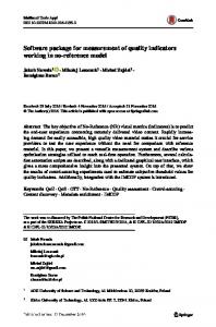
Development of a Software Package for Calculating Current Rating of Medium Voltage Power Cables D.G.A.K.Wijeratna, J.R. Lucas, H.J.C.Peiris, H.Y.R.Perera Department of Electrical Engineering, University of Moratuwa, Sri Lanka ABSTRACT
•
There are instances where the application of the ampacity tables including the safety margins is insufficient, requiring engineers, installers, and inspectors to perform actual ampacity calculations. This is specially true as higher ampacities are requested, and as it becomes more difficult to install new circuits, so that the existing circuits must be operated more efficiently.
•
And for specialized applications or usually for higher voltage application, ampacities cannot be found in these ampacity tables and it has to be calculated.
The conventional method in calculating cable ampacity is to calculate it under prescribed conditions and then to apply derating factors to cater for real conditions. Most of the power cable manufacturers use this approximate value for designing power cables, which results in unnecessarily manufacturing cost. If we can consider the real conditions (Installation methods and operating conditions etc.) in the calculation procedure, more accurate values can be obtained and it will help in the economic design of power cables. As this method involves complicated mathematical formulae, it is necessary to have a computer program for handling the calculation part. The CableAmp program developed handles this situation. It is a Windows based software, which was developed using Microsoft Visual Basic. The CableAmp can calculate the ampacity of medium voltage power cable laid in free air or directly buried in the ground. [The user has to input the required data of the cable design as well as the cable installation method to the program]. CableAmp can calculate the continuous current rating (at 100% load factor) as well as the cyclic current rating (according to the specified load profile) of the power cable. The Calculation procedure is in accordance with International Standard IEC 287. Presently it has been developed to handle power cables operating at voltages in the 6 kV and 33 kV voltage range. Index Terms Software, power, cable, current, rating, ampacity,
1.0
INTRODUCTION
For most of the power cable applications the ampacities can be found in cable manuals. These ampacity tables can be obtained form the cable manufacturers also. Normal procedure in calculating the current rating of a power cable is to calculate the current rating under prescribed conditions and then to apply appropriate derating factors to cater for actual installations methods and operating conditions. Thus the existing ampacity tables are crude approximations and include substantial safety margins. Problems associated with conventional methods are as follows. •
Sometimes there are no derating factors to address different types of installation methods and excessive thermal heat effects.
Transactions of the IEE Sri Lanka – September 2003
50
The answer to these problems is to consider the actual installation methods and operating conditions in calculating the current rating. By using the proposed approach, more accurate ampacity values can be obtained. As the optimum conductor sizes can be obtained, the power cables can be designed more economically. This involves complicated mathematical calculations and thus the need of this kind of software arises. In the international market, there are software packages for doing such calculations. However, the prices of these are in the range of one to two millions rupees. Thus this package was developed as part of an M. Eng Degree at University of Moratuwa. This will be useful to the cable manufacturing industry. The programming language that has been used for developing this software is Microsoft Visual Basic, which provides high user-friendly features. This program provides convenient calculation facility of the continuous current rating as well as the cyclic current rating of power cables with extruded solid insulation from 6 kV to 33kV.
2.0
FUNDAMENTALS OF CALCULATING CURRENT CARRYING CAPACITY
The basis for most high-voltage underground ampacity calculations worldwide is an international standard, IEC 287. IEC 287 covers medium-voltage and highvoltage cables, many different constructions, and many installation types. While the Neher-McGrath method to calculate ampacities is the predominant method used in the U.S., IEC 287 is the predominant method used internationally.
D.G.A.K.Wijeratna, J.R. Lucas, H.J.C.Peiris, H.Y.R.Perera
Both methods employ the application of thermal equivalents of Ohm's and Kirchoff's Laws to a simple thermal circuit. In this program the method covered in the IEC 287 was used. When the conductor is energized, heat is generated within the cable. This heat is generated due to the I2R losses of the conductor, the dielectric losses in the insulation and losses in the metallic component of the cable. The ampacity of the cable is dependent on the way this heat is transmitted to the cable surface and ultimately dissipated to the surrounding. As shown in the figure 1 the cable materials and soil represent a series circuit of thermal resistances. The thermal resistances control heat dissipation from the conductor.
From equation (2) a formula can be obtained for the permissible current as given in equation (3). I=
power cable
Thus the efficiency of heat dissipation is dependent upon the various thermal resistances of the cable material and the external backfill and soil plus the ambient temperature around the cable. If the cable is able to dissipate more heat, the cable can carry more current. The normal maximum continuous rating of the cable is dependent on a number of factors. Of these the one that is most important is the maximum permissible conductor temperature. The maximum permissible current rating is the loading in amperes which, applied continuously until steady conditions are reached, will produce the maximum allowable conductor temperature. Steady state is reached when the rate of heat generation in the cable is exactly equal to the rate of heat dissipation from the surface of the cable. This steady state is the only condition considered when calculating the maximum permissible continuous current rating. By applying the thermal equivalence of Kirchoff’s and Ohm’s law to the circuit shown in figure 1, equation (1) is obtained. T=H*S
(1)
The expression (1) can be rewritten by substituting cable parameters and gives equation (2).
The program uses this formula for calculating continuous current. The other parameters of the formula should be separately calculated dependant on the various other factors like cable construction types, installation types, installation environment.
Cyclic Loading
As very often happens, the loads are cyclic rather than continuous. Many cables, particularly buried cables, may take up a longer time for the temperature to build up the equilibrium condition on which the continuous ratings are based on. Generally the continuous rating is used as a guide, but when the load is cyclic higher ratings should be used than with continuous operation. In cyclic operation, a cable can carry a significantly heavier load for a given maximum conductor temperature than during constant load because the cable, and sometimes its environment, is capable of storing heat during periods of peak load and dissipating this stored heat when the load diminishes. Many factors have to be taken into account in calculating these cyclic ratings. Cable diameter in relation to the environment has a major effect, because surface area increases with diameter. Other factors are the type of cable, the effect of any other cables in the vicinity and the thermal resistivity of the soil. 2.1.1
Cyclic rating factor (M)
The cyclic rating factor is defined as the factor by which the permissible continuous current rating (100% load factor) can be multiplied to obtain the peak load current during a daily load cycle, such that during this cycle the conductor reaches, but does not exceed, the standard maximum permissible temperature.
The program can calculate this parameter after calculating the permissible continuous current rating if the detail of the daily load cycle is available (as 24 hourly values).
2
∆θ = (I R + 0.5 Wd) T1 + [I R (1+ λ1)+ Wd] nT2 + [I2R (1 + λ1 + λ2)+ Wd] n (T3+T4) (2)
Transactions of the IEE Sri Lanka – September 2003
(3)
For cables in air the conductor temperature follows changes in the load current sufficiently rapidly so that the usual daily cycle do not permit peak loads greater than the steady state value. Usually the cyclic rating factor is taken as unity for cables in air.
Where T is the temperature difference in cesius, H is the flow of heat in watts, S is the thermal resistances in thermal ohm.
2
0.5
[The meaning of the different symbols are given in the Appendix]
2.1
Figure 1- Thermal Circuit model of a 3-core metal-sheathed
∆θ-Wd [0.5T1+n (T2+T3+T4)] RT1 +nR (1+λ1) T2+nR (1+λ1+λ2)(T3+T4)
51
D.G.A.K.Wijeratna, J.R. Lucas, H.J.C.Peiris, H.Y.R.Perera
2.2 Important parameters affecting ratings 2.2.1
Conductor
Temperature
Insulation
Temperature rise is the most important parameter, but this is governed by the base ambient temperature for the given cable location and the maximum temperature applicable to the insulation and cable construction. For buried cables, if the soil is warm it absorbs less heat and consequently the rating will be reduced. 2.2.2
Armour
•
A direct buried cable dissipates heat more readily than a cable in a duct.
•
For buried cables the rating decreases with the depth of burial, because (it is assumed) the heat finally goes to the ground surface. A deeper cable sees more total soil resistance.
•
Soil thermal resistivity is also an important factor. This determines how well the soil carries away the heat. Adjacent cables contribute heat and may induce additional losses in the cable itself. Closer cables have more effect in reducing the rating.
2.2.3 Shielded grounding Multipoint grounding increases circulating currents in the sheath. Therefore the losses will be increased and the rating will be decreased. Single-point grounding eliminates sheath currents, but induced voltages on the sheath has to remain within given limits even away from the grounded point. 2.2.4 Cable Design The cable design determines the ability to transfer heat from the conductors to the outer surface. This varies with the materials used and the number of layers in the construction.
3.0
Bedding
Conditions of Installation
A cable in air generally dissipates heat better than a cable buried in the ground, but in this respect the cable diameter (or more particularly the surface area) is more important. A few important points to note are as follows.
•
Sheath/Screen
POWER CABLE LOSSES
A power cable consist of several components, some of which may or may not be present dependant on requirements. The conductor and the insulation are the most basic components seen in any power cable. As the voltage increases other components are added to handle higher electrical stresses. Figure 2 illustrates a cross section of a power cable which consists of a bedding, metallic sheath, steel wire armour and an outer jacket.
Transactions of the IEE Sri Lanka – September 2003
52
Outer Serving
Figure 2 - Cross section of a single core metal sheathed, wire armoured power cable.
Nearly every part of a cable produces heat in one way or another. Within the external periphery of the cable there are four heat sources produced by losses in the following.
3.1
i.
Cable Conductor
ii.
Metallic Sheath/Screen
iii.
Cable Armouring
iv.
Dielectric
Conductor I2R Loss
A loss occurs in the cable conductor, which is proportional to the conductor resistance and to the square of the current being carried and it is known as “I2R loss”. This loss normally represents the largest heat source in the cable. When the cable carries a.c. currents, the conductor resistance increases due to the skin and proximity effects. Skin effect is a phenomenon, which accounts for the increase in resistance of a conductor due to selfinductance. This effect causes the current density in the conductor to be higher towards the outer surface. Although skin effect is generally considered negligible at power frequency, the effect becomes significant with larger cross sections (greater than 150 mm2). Proximity effect is a phenomenon of mutual inductance between the conductors of adjacent phases which creates the tendency for the currents in these conductors to flow along one side of the conductor cross section. This effect can be disregarded for cables smaller than about 185mm2 cross section.
3.2
Sheath/Screen Losses
The magnetic fields of the currents flowing in the conductors induce e.m.f. s in the metallic sheath/screen , which under certain conditions causes heavy currents to flow in the sheath/screen and generate losses.
D.G.A.K.Wijeratna, J.R. Lucas, H.J.C.Peiris, H.Y.R.Perera
There are two types of losses which occur as sheath eddy loss and the sheath circulating loss. Sheath eddy loss is due to the induced eddy currents, which flow circumferentially in the sheath/screen of the three-core cable or in the sheath/screen of the three single core cables. This loss reaches its maximum value when the cable conductors are situated as close as possible to one another. The loss can be reduced by increasing the sheath resistance and by increasing the ratio of cable spacing to sheath diameter. In many instances this loss is small and can be disregarded. The sheath circulating loss, which only occurs in single core cables systems, is due to induced current flowing along metallic sheath/screen and returning through the sheaths of the other phase or through earth. This only exists when the sheaths of two or three single core cables are bonded together at two different positions, such as the ends of the cable route. This loss decreases as the sheath resistance is increased and the three cables are placed closer together. However, the closer formation results in a greater eddy loss and also increases the mutual heating of the three cables.
3.3
•
Losses due to currents in the armouring, both in the form of circulating currents and eddy currents. Losses due to magnetic field around the cable conductor under consideration and also losses due to the fields caused by currents in other conductors of a group of single core cables. These combined magnetic fields produce significant hysterisis losses.
The main procedure followed in designing software can be divided into four steps. The first step is to obtain the system of equations from the IEC standard. The algorithm is then developed according to the system of equations. This algorithm is used for writing the program with Microsoft Visual Basic. The final step is obtaining the required output from the program. The main algorithm (i.e. the procedure for obtaining the current rating of a power cable) is shown as a flow chart in figure 3 . Start Calculate temperature difference (∆θ)
Calculate sheath loss factor (λ1) Calculate armour loss factor (λ2) Calculate thermal resistances T1, T2, T3, T4 Calculate continuous current (Icont)
The details of the daily load cycle available ?
yes
Dielectric Loss
The dielectric losses of a.c. cables are proportional to capacitance, the frequency, the phase voltage and loss factor. The loss component of the loss factor (or the power factor) is made up of the following. •
Leakage current flowing through the dielectric, which is independent of frequency.
•
Dielectric hysterisis, which is caused by the interaction of alternating field with the molecules of the constitutants of the insulation and is only present with a.c. voltage application. This is by far the largest effect.
•
METHODOLOGY
Calculate A.C. resistance (R)
For power cables with non-magnetic armour, the usual practice is to take the combined sheath and armouring resistance as a whole and to calculate all losses as sheath losses.
3.4
4.0
Calculate dielectric loss (wd)
Armour Loss
Armour losses usually consist of the following. •
The power factor of the cable insulation is dependent on frequency, temperature and applied voltage. It is of a very low order for low and medium voltage cables but this value rises rapidly with higher voltages.
Ionisation i.e. partial discharge in the dielectric.
Transactions of the IEE Sri Lanka – September 2003
53
no Calculate cyclic current End
Figure 3- Flow chart of the main calculation procedure
4.1 Calculate Temperature Difference (∆θ) This is the the maximum permissible difference of operating temperature (between the cable and the ambient temperature).
D.G.A.K.Wijeratna, J.R. Lucas, H.J.C.Peiris, H.Y.R.Perera
The maximum operating temperature varies according to the type of insulation used. The ambient temperature is usually taken as 30 oC for above ground installations and 20 oC for underground installations.
4.2
Calculate Dielectric Loss (Wd)
As the dielectric loss is voltage dependant, it is taken into account for values of equal or greater than the limiting voltage level Uo related to the insulation material being used. Typical values are as follows. Insulation Material PVC XLPE
U0 (kV) 6 63.5
The dielectric loss per unit length in each phase is given by equation (4). Wd = ω CU02 tanδ
(W/m)
(4)
4.5.1 Non-Magnetic Armour The general procedure is to combine the calculation of loss in the armour with that of the sheath. In place of sheath resistance, a parallel combination of sheath and armour can be used (The root mean square value of sheath and armour diameter replaces the mean sheath diameter). 4.5.2 Magnetic armour For the magnetic armour λ2 is calculated according to the armour type (i.e. steel wire or steel tape) and the number of cores in the cable.
4.6 Calculate Thermal resistances The heat path from the cable conductor(s) to the “sink” of heat, traverses the following items in turn.
4.3 Calculate A.C. Resistance (R)
Insulation Armor
When considering steady conditions there is no longitudinal heat flow in the cable, so that it is immaterial what length of the cable is considered when calculating the rating. It is convenient to use 1m.
The thermal resistances of metallic portion of this heat path are so small in comparison with others. Therefore they can be neglected and the list now reduces to,
The a.c. resistance per unit length of the conductor at its maximum operating temperature is given in equation (5)
R = R' (1 + y s + y p ) 4.4
(5)
Calculate Sheath/Screen Loss Factor (λ1)
It is convenient to express sheath/screen losses as a fraction of the conductor losses, as both are dependant on the square of current. The power loss in the sheath or screen consists of losses caused by circulating current (λ1’) and eddy current (λ1”) and is given in equation (6) λ1=λ’1 +λ”1
(6)
For single core cables with sheath bonded at both ends of an electrical section, only the loss due to circulating current in the sheath needs to be considered. An electrical section is defined as a portion of the route between points at which the sheath or screens of all cables are solidly bonded.
4.5
Calculate Armour Loss Factor (λ2)
The armour loss represents the power loss occuring in the armour as a factor of total power losses in all conductors. The calculation of loss factor depends on the type of the armour. (i.e. Non-magnetic or Magnetic armour)
Transactions of the IEE Sri Lanka – September 2003
54
Metallic sheath Outer Serving
Insulation(T1) Outer Serving (T3)
Bedding Ground or air
Bedding (T2) Ground or air(T4)
The total thermal resistance consists of resistances partly in series and partly in parallel, so that it is necessary to figure out the values of these so called partial thermal resistances. Each partial resistance can be split up into two factors, one being essentially the thermal resistivity of the material and the other a function of the material through which the heat passes (The latter factor being called the geometric factor). The dimensions of the cable affect the thermal resistance, and calculations can be made in the case of single core cables, as the heat flow is radial to the core. However, multicore cables offer a very complex problem owing to the distortion of the lines of heat flow. This problem has been resolved by the use of geometric factors. The calculation of these factors T1, T2, T3 is dependant on the cable materials and cable type. With cables buried in the ground the heat transmitted through the cable passes into the surrounding soil. No conclusive evidence is available regarding the nature of heat flow in the soil, but the basis used for calculation accepts the theory that the ground surface above the cable is plain isothermal of ambient temperature, so that all the heat generated is ultimately transmitted to the ground surface, which remains at constant temperature. In general soil having a higher percentage of moisture will have a lower thermal resistivity and consequently the best heat dissipating qualities.
D.G.A.K.Wijeratna, J.R. Lucas, H.J.C.Peiris, H.Y.R.Perera
Porous or well-drained soils have a higher thermal resistivity. In the program four types of soil have been considered according to the different weather conditions. If there is a variation in soil resistivity over a period of twelve months, the current rating should be based on the highest value of soil thermal resistivity observed. With cables carrying a heavy load continuously, some drying out of the soil immediately surrounding the cable may occur, increasing the value of soil thermal resistivity. But in the program it is considered that soil drying out does not occur and the value of soil thermal resistivity remains constant during the operation of the cable. The value of T4 is calculated considering all these factors.
Thus this software has been developed to meet the need for modern engineering software tools, and it can be used with minimal training. This application can be easily customized to the materials and practices used by each member utility, allowing the ultimate user (for example, a design technician with limited engineering expertise) to apply the program with maximum efficiency and minimum complexity. 5.1.1 Factors to be taken into account in using the software • • • •
4.7 Current Rating 4.7.1 Calculate Continuous Current Rating (Icont)
Ambient temperature − Above ground installation- 30oC − Underground installation-20oC Power Frequency – 50 Hz Voltage – between 6 kV and 33 kV Installation Method – Single circuits directly buried and laid in free air (protected from or exposed to solar radiation)
The continuous current rating of the cable Icont is calculated using the equation 3 given in section 2. However, this equation has to be adjusted for catering to the effect of intensity of solar radiation, for cases of cables laid in free air and directly exposed to the solar radiation.
5.2
4.7.2 Calculate Cyclic Rating
For each component of the cable, a separate dialog box is introduced and the user can enter the dimensions, material and type of the particular component. Before entering the data the user is given an option for selecting whether a particular component is existing or not in the cable design, because other than the main components (the conductor and the insulation) some components may not always exist in a cable design. The installation environment of the cable is very important in ampacity calculation and the user can enter the laying method, installation method and the soil condition for underground installations.
Calculation of cyclic rating is varies according to the details known about the daily load cycle. For this program it is considered that only the loss load factor (µ) of the load cycle is known. (Which can be calculated using the 24 hourly load values ). The cyclic rating factor (M) can be calculated using the equations given in the IEC 853 standard. The cyclic rating is obtained by multiplying the value of continuous current (Icont) by the cyclic rating factor. 4.7.3 Assumptions made in the Current Rating Calculation Procedure
•
Soil drying out does not occur.
•
Conditions do not vary along the cable route.
•
No axial heat transfer takes place.
•
Ground ambient temperature remains constant.
Once all the needed data has been entered, the user can proceed to the calculation part. The continuous current rating as well as the other parameters of the cable like a.c.. Resistance, dielectric loss, loss factors of metallic components and thermal resistances of relevant layers of the cable can be viewed on the screen by clicking a button on the screen. The user is also provided with the facility of altering the previously input data. The output results automatically updates accordingly. 5.2.3 Calculation Cyclic Rating
5. 0 THE SOFTWARE An Overview
Users of Windows based software tools have become to expect a user-friendly graphic interface for performing their tasks.
Transactions of the IEE Sri Lanka – September 2003
The program consists of several dialog boxes where the user can input the required details of the cable design for the calculation of current rating. Some data is user defined while some data has to be selected from a menu.
5.2.1 Calculation of Continuous current rating
The following assumptions have been made.
5.1
The Operation
55
For buried cables, if the pattern of the daily load cycle is available (The user has to enter the value of the load hourly for 24 hours in per unit values. i.e. Divide the each hourly value by the maximum value of that cycle) the program can calculate the cyclic rating of the cable.
D.G.A.K.Wijeratna, J.R. Lucas, H.J.C.Peiris, H.Y.R.Perera
5.2.4 Reporting
•
Flexibility is provided in easily specifying the information to include in the final report including input data and calculation results. Reports can be directly printed out, previewed on screen and exported to TXT or HTML formats.
•
5.2.5 Error Handling The program needs all the required data of the cable components and the installation type as the input for the program. In the case of missing the required data the program may get halted while executing or may output incorrect results. There are several techniques used in the program for preventing the occurrence of this and for justifying the correctness of the output results.
5.3
The Results
A sample data from a cable’s manufacturer’s data sheet is included in the program for the demonstration purposes of the software. Data is included for two cases as • 12 kV direct buried three core cable and • 18 kV direct buried three single core cables.
A series of cables sizes can be selected and the current rating can be calculated for different installation methods and from that the optimum size can be selected which lies in the economic range while giving the desired load capacity. Apart from that the cable materials and the dimensions of different layers can also be changed according the cost of these materials in designing the cables economically. Engineers familiar with manually performing cable calculations will be happy with the flexibility and robustness of this software. The customer can use this program as a guide for checking the correct ampacity values specified by the manufacturer if the details of the cable are given to the customer when purchasing a new cable.
6.1
6.0
CONCLUSION
Simply stated the purpose of this project is to calculate current rating of a cable based on a set of user inputs. User inputs include, but are not limited to cable dimensions and materials, cable layout and cable operating conditions. The program is useful for both the customer and the manufacturer. This also permits quick and easy comparison between cable manufacturers and designs.
Suggestion for the improvement of the software •
The results obtained for the value of the continuous current ratings were about 15% higher than the values given in the cable manufacturer’s data sheet. However as the details of the installed environment (like buried depth, soil condition/weather condition etc.) are not given in the data sheet, the values are more conservative in the data sheets. Thus the calculated values cannot be directly compared with the values given in the data sheet, and the values obtained can be considered to be acceptable.
Consolidates many calculations into one simple to use program Can be used as a tool in designing cables economically
• •
7.0
A financial analysis can be included with the program for automating the economic design of cables. Other types of cables such as pipe type cables and oil filled cables can be considered. Calculations can be expanded to consider high voltage power cables. (greater than 33 kV)
ACKNOWLEDGEMENT
The authors wish to express their deepest gratitude to to the staff members of the department of Electrical Engineering, University of Moratuwa for the help given in making the project a success. They also wish to thank Mr. Chandana Samarasinghe of CEB for supporting them to obtain the required IEC standards. Thanks are also due to Mr. K. Sooriyabandara of Kelani Cables (Pvt.) Ltd. for the assistance given. Finally the support given by Dr. K.M. Liyanage and the staff at the Computing Centre, University of Peradeniya in completing the project successfully is deeply appreciated.
8.0
REFERENCES
In short this software is a valuable tool because it • • •
Automates time consuming process Handles many cable types and configurations Provide quick and accurate results without table lookups
Transactions of the IEE Sri Lanka – September 2003
56
[1]
Barnes C.C. Power Cables: Their Design and Installation. London: Chapman & Hall Ltd., 1966.
D.G.A.K.Wijeratna, J.R. Lucas, H.J.C.Peiris, H.Y.R.Perera
[2]
British Insulated Callender’s Cables Limited. High Voltage Cables, 2nd edition, 1948.
[3]
King S.Y., N.A. Halfter. Underground Power Cables. New York: Longman Inc., 1982.
[4]
MacAllister D. Electric Cables Handbook. London: Granada Technical Books Ltd., Part II, III, and I 1982.
[5]
Siler B. , Spotts J. Using Visual Basic 6. New Delhi: Prentice-Hall of India, 1998
[6]
IEC 287-1-1:1994”Electric CablesCalculation of current rating-Part 1”, 1st edition
[7]
IEC 287-2-1:1994 ”Electric CablesCalculation of current rating-Part 2”, 1st edition
[8]
IEC 853-1:1985,”Calculation of the cyclic and emergency current rating of cables- Part 1 “, 1st edition
[9]
Powers W.F. The basics of power cables,www.southwire.com/tech/library, June 2001.
[10]
Newton G.C. www.electrician.com/articles, January 2000
Transactions of the IEE Sri Lanka – September 2003
57
Appendix LIST OF SYMBOLS C =Capacitance per core per unit length (F/m) I =Permissible continuous constant current (100% load factor) in one conductor of the cable. (A) M =Cyclic rating factor R =a.c. resistance of conductor at maximum operating temperature (Ω/m) R' =d.c. resistance of conductor at maximum operating temperature (Ω/m) T1 =Thermal resistance between the conductor and sheath (K.m/W) T2 =Thermal resistance between sheath and the armour (K.m/W) T3 =Thermal resistance of the outer serving.(K.m/W) T4 =Thermal resistance of the surrounding medium. (K.m/W) U0 =Voltage between one conductor and screen or sheath. (kV) Wd =Dielectric Loss per unit length per phase (W/m) n =Number of current carrying conductors in the cable. ys =Skin effect factor yp =Proximity effect factor ∆θ =Temperature difference (K) λ1 =Sheath loss factor λ2 =Armour loss factor ω =Angular frequency of the system (2∏f) µ =Loss load factor
D.G.A.K.Wijeratna, J.R. Lucas, H.J.C.Peiris, H.Y.R.Perera