ABCM Symposium Series in Mechatronics - Vol. 2 - pp.150-157 Copyright © 2006 by ABCM Proceedings of COBEM 2005 Copyright © 2005 by ABCM
18th International Congress of Mechanical Engineering November 6-11, 2005, Ouro Preto, MG
DEVELOPMENT OF AN OPEN DISTRIBUTED APPROACH FOR BUILDING AUTOMATION Gladys Bastidas University of São Paulo, Escola Politécnica, Brazil
[email protected]
Paulo Eigi Miyagi University of São Paulo, Escola Politécnica, Brazil
[email protected]
Israel Benítez Pina University of Amazonas State, Escola Superior de Tecnologia, Brazil/ University of Oriente, Cuba
[email protected]
Abstract. The demand for more efficient, reliable and safe systems has beneficed the development of new concepts for buildings automation. These features can be achieved through an effective building systems integration. However, considering that each building system has unique characteristics, the requirements specification, verification, validation and implementation of an integrated solution are complex tasks, possibly leading to an unreliable automation system. Thus, an adequate approach for treat these systems, is fundamental to manage them and to assure effectively its integration. On the other hand, treat the building system integration with characteristics of open distributed systems can provide solutions for many problems related to aspects such as flexibility, investment preservation, connectivity and interoperability. Then, in this paper Open Distributed Processing - ODP is introduced as a general framework upon which open distributed system can be modeled through the viewpoint concept and the use of an object oriented language (Unified Modeling Language UML). The Petri net (PN) is also considered because it could provide a effective model analysis. In this context, the purpose of this work is to introduce an open distributed approach for building automation based on the merging of ODP framework, UML and PN. Keywords: building automation, ODP, UML, Petri Nets 1. Introduction In the context of building automation, the functional and operational improvement of building systems is an imperious necessity. The purpose of this kind of automation is to allow an efficient management of resources and to minimize cost through the integration of its systems (Callaghan 2000). Furthermore, the integration among these systems should increase the productivity of the building occupants and improves comfort, management of resources, energy conservation and reduces costs. Therefore, the benefits of building automation lie on the selection of the most suitable systems to fulfill specific goals and in the integration of the various building systems in order to achieve these, both efficiently and economically (Wong et al.,2005, Wang and Xie, 2002). Considering these characteristics, building automation design can be seen as a task involving techniques and methods of several areas. Thus, a mechatronics approach can help to treat the integration among building systems and improve the performance of the building automation. In system automation, the development of open distributed control systems can provide solutions for many problems related to aspects such as flexibility, investment preservation, connectivity, interoperability with other systems and portability (Faroqui et al. 1995). Regarding building automation, these advantages are particularly desired once that allows the integration of building systems. Concerning the open distributed systems, the reference model of Open Distributed Processing (ODP) offers a general framework upon which open distributed systems can be development (Gazpos, 1996). In this context, the purpose of this work is to introduce a novel approach for building automation design based on the ODP and the utilization of object-oriented concepts through Unified Modelling Language (UML) and formal models such as Petri nets (PN). The PN model is used throughout the process in order to guarantee the coherence among the UML models from requirement analysis to implementation. Furthermore, the Petri net model allows formal verification of behavior properties of the automation system before implementation and testing phases, reducing costs and time. This paper is organized as follows: Section 2 describes open distributed systems. Section 3 describes the synergetic merging of ODP, UML and Petri nets. In section 4 the proposed approach is introduced through an example. Finally, section 5 draws some conclusions and outlines future works.
2. Open Distributed Systems An open distributed system provides capabilities that enable properly implemented applications to run on a variety of platforms from multiple vendors and inter-operate with other systems applications. Therefore, the main motivations for the adoption of open distributed systems are interoperability, portability, scalability and interchange ability (Pianegiane, 2002; Katchabaw et al., 1999). In this context, when approaching the building automation systems as open distributed system all the characteristics of these systems should be able to allow a complete integration and an efficient management of resources and costs. For modeling open distributed systems, a reference model named Open Distributed Processing (ODP) has been used 2.1. Reference Model ODP (Open Distributed Processing) The reference model for open distributed processing (ISO/IEC 1995) is a joint effort of the International Standardisation Organisation (ISO) and the International Telecommunication Union (ITU). The objective is to provide a unifying architectural framework for the standardisation and construction of open distributive systems (Gazpos 1996). This reference model address issues associated with the development of large-scale, heterogeneous, distributed systems in a multi-vendor environment. It provides a framework for the specification and the development of open distributed systems according to five different viewpoints (ISO/IEC 1995). Each ODP viewpoint provides a different abstraction of the systems focusing on a particular area of interest. The ODP identifies five well-defined viewpoints: enterprise, information, computational, engineering and technology: Enterprise viewpoint: focuses on purpose, scope, policy and boundaries of a specified system. The main concepts of the enterprise viewpoint are roles, communities and objectives; Information viewpoint: is concerned with the information and the information processing function of the system. How the information is structured, how it changes, information flows, and the logical divisions between independent functions within the system; Computational viewpoint: focuses on functional decomposition of the system into objects, which interact by their interfaces; Engineering viewpoint: focuses on how distributed interaction between system objects is supported (infrastructure required to support distributed processing); Technology viewpoint: concentrates on the individual hardware and software components, which make up the system (suitable technologies to support distributed processing). 3. ODP, UML and Petri Net: A sinergetic association The ODP defines concepts and structuring rules for specifying open distributed systems. In particular ODP deals with the separation of concerns needed to specify different facets of a system through five viewpoints. It is important to observe that the ODP does not define the way of representing each viewpoint, although it imposes an object-oriented modeling. In the present work are used the UML diagrams. Following this trend, this work proposes an approach for building automation design where Petri net models and UML diagrams are alternately used, guided by the ODP viewpoints. On the one hand, Petri net models are a “link” among UML diagrams. On the other hand, UML complements Petri net models especially for object oriented aspects and systematize the analysis procedures. In the context of object-oriented modeling, the UML has been adopted increasingly as a pattern. Among its advantages, there is the ability to represent different perspectives (structural/static and behavior/dynamic) of the system and with different levels of details. Briefly, the UML could be described as a language that, starting from a set of basic elements (such as classes, use cases, interactions, states, etc) and the possible relationship among these elements (such as composition, inheritance, etc.), defines a set of diagrams for representing different views of the same system (OMG, 2003, Booch et al. 1999). Although its advantages, the UML has still some points to be improved (Giese et al. 1999). Among the problems are the system behavior description and issues concerning parallelisms, synchronism and concurrency among processes. In order to improve the behaviour description of the discrete aspects, some works has been development trying to merge UML and Petri nets (Giese et al. 1999, Baresi and Pezze 1999). The main advantage of Petri net is its effective formalism for representing and analysis of sequence, conflicts, resource sharing, parallelism, synchronization and causality process. These features make them a promising tool for describing and analyzing concurrent and real-time systems. In addition to their modeling power, Petri net is both a graphical tool and a mathematical formalism. As a graphical tool, they provide a visual tool for the modeler to describe complex system and present it to users. As a mathematical formalism, a Petri net model can be represented by a matrix notation, which allows the formal verification of behavior and structural properties. Following this trend, this work proposes an approach for building automation design where Petri net models and UML diagrams are alternately used, guided by the ODP viewpoints.
Proceedings of COBEM 2005 Copyright © 2005 by ABCM
18th International Congress of Mechanical Engineering November 6-11, 2005, Ouro Preto, MG
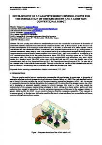
4. Proposed Approach The proposed approach for building automation design is based in the application of the ODP viewpoints through of use UML and Petri net aiming the modeling and the system analysis. To introduce the main features of the proposed approach, the modeling and analysis of the building system of a hospital is used as example. In this example are considered the following buildings systems: the security system (access control), fire system, HVAC (Heating, Ventilation and Air Conditioning) system, and lighting system The proposed approach encourages iterative development, by allowing the various activities to provide input to each other. Three major complementary activities are defined, which are refined forward. Figure 1 shows the high-level development activities and how they relate to ODP. Activity 1.1: Requirements
1. Domain Modeling
Activity 1.2: Definition of system domains and use case modelling
Enterprise Viewpoint
2. Modeling of relationships and services of the system Information and Computational Viewpoint
3. Dynamic Modeling and Formal analysis
Activity 2.1: Abstraction of the relationship and interactions through Petri Activity 2.2: Definition and construction of class diagram
Activity 3.1: System Modelling through Petri nets Activity 3.2: Formal Analysis
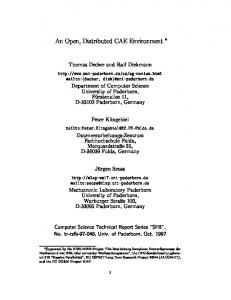
Figure 1. Details of the proposed approach 4.1. Domain Modeling The domain modeling concerns business process and identification of goals and requirements. The results of this activity are related to “enterprise viewpoint” and defines an overview of the system. During the business process analysis, domains systems are identified. Here is represented the functionality of the building automation system in a higher level of abstraction. The “enterprise viewpoint” defines the purpose, scope and actors of the building automation system being developed. This viewpoint provides the most abstract description of the system being modeled. The information captured in the enterprise viewpoint is used to communicate with the user of the systems being developed and to serve as the basis for delimiting the systems with respect to their environment. One of the important characteristics of the “enterprise viewpoint” is its relative independence from the target application. The information present at this level is mainly domain specific, it is common to several applications in this domain. This activity is separated in two sub activities: 1. Requirements The requirements concern identification goals and expectations, areas of concern and identification of them. In a hospital building the most important requirements related to building automation are integration, flexibility, safeness, interoperability, reliability, adaptation to environment (specially lighting system and HVAC systems) and management. 2. Definition of system domains and use case modeling In this activity concepts specific about the system domain and the required functionality of the system are described. UML use case diagrams are used to describe this functionality. The hospital incorporates four domains that interact among themselves: administration, building systems (lighting, fire, HVAC, security), users (patients, visitors or employees) and service companies (supply water, energy, telecommunications and gas). The model in UML is illustrated in Figure 2 (a). Considering specifically the hospital building systems, each system is a domain with specific control functions that interacting in order to achieve their goals. Figure 2(b) presents the hospital building systems and their interaction.
Hospital Building
Hospital Building Systems Building systems
Administration
Supervisory System
Service Companies Water Energy Telecom. Gas
Users Patients Visitors Employees
Fire System
Access System
Lighting HVAC Access Fire
HVAC System
Lighting System
(a) Interaction between objects enterprise viewpoint; (b). Hospital building system interaction Figure 2. UML package diagrams of systems domains Considering the hospital building systems, the interactions between actors and theirs systems should be identified. This is a way for defining the responsibilities for each system (Figure 3). Building systems Request service Users
Patients
Visitors
Realize maintenance
Employee
Management services
Employees
Manager Supervision Monitoring
Figure 3. UML Use-Case diagram of building systems The UML use-case diagram in Figure 4 can be detailed. Thus, the use-case ‘request service’ include all functionality of the buildings systems like: heat, cool, ventilation, increase or decrease lighting, authorize entry, detect and control fire, etc. Specifically taking by example the fire and HVAC system. The fire systems has as its main purposes to detect fire and act on the building systems in order to minimize the potential damage of the fire. Some of its functions are: - Detect fire by monitoring a set of sensors (temperature sensor, fire sensor, smoke sensor, etc). - In case of fire, act on sprinklers, insufflators, etc. - In case of fire, communicate other building systems, such as HVAC system, lighting system, and access control system. - In case of fire, communicate the fire brigade. - Provide routines and functions for the test of fire equipment and fire strategies. Considering these functions, an example of fire system UML use-case diagram is presented in Figure 4 Fire System Fire brigade
use
Communicate fire detection Building systems
Detect fire and control it Turn on fire system Fire system operator
Test fire equipment
Figure 4. UML Use-Case Diagram of Fire system The HVAC system has as its main purposes to keep environmental control. Some of its functions are: - To provide heating, cooling and ventilation facilities. - Change the ventilation system according to fire system information. - Provide routines and functions for the test of HVAC equipment.
Proceedings of COBEM 2005 Copyright © 2005 by ABCM
18th International Congress of Mechanical Engineering November 6-11, 2005, Ouro Preto, MG
The example presented in this paper considers only cooling and ventilation facility in order not to overcharge the models and to focus on the proposed approach Considering these functions, an example of HVAC system UML Use-Case Diagram is presented in Figure 5 HVAC System Cooling User
Building systems
Ventilation Turn on HVAC system HVAC system operator
Test HVAC equipment
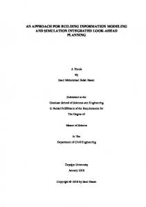
Figure 5. UML Use-Case Diagram of HVAC system 4.2. Modelling of Relationships and Service of the System In this activity, two main aspects of the system modeling are concurrently focus: objects and information flow. This activity concerns to information viewpoint and computational viewpoint. This activity is divided in two sub activities: 1. Abstraction of the relationship and interactions through Petri nets This sub activity drives the descriptions of the information that are changed among the hospital building systems. The specification of the information is generated from the component identified in the enterprise viewpoint. The information that the system considers is modeled in accordance with the behavior of the system. Here the information elements, the information structures and the requirements for information handling among objects of the building systems are identifying. For the information modeling each system is detailed by defining what is the information that need to be modeled and how it is processed. The information considered for the example is supply for each hospital building system. The information of the fire system is share with the HVAC system, lighting system (signalize escaping routes) and access system (number of people in zones with fire and unlock entrances). This information allows that this system can perform their fire strategy. Specifically considering the information of the fire system share with the HVAC system the propose is to help the smoke removing and preventing smoke to spread throughout the building. Some of the activities in the HVAC system fire strategy are: - Turn on ventilators in places with fire. - The mixing box is set to take 100% of outside air. - Valve controllers are turned off in order to avoid an eventual unbalance of the systems due to the great demand of cold water. Based on this description, the modeling of the information interchange is realized using a Condition/ Event (C/E) Petri net (Figure 6). Detect High Temperature (Temperature sensor)
Detect Smoke (Smoke sensor) Detect fire (Fire Detector) Turn on alarm (Alarm)
Turn on Pump (Pump)
Turn on Insufflators (Information HVAC system)
Number of people in zones with fire (Information Access system)
Turn on Emergency Lights (Information Lighting system)
Unlock entrances (Information Access system)
Turn on Sprinklers (Sprinklers)
Figure 6. Petri Net model of information in fire and other building systems
2. Definition and construction of class diagram This sub activity is concerned with the functional decomposition of systems into objects and the identification of the relationships, allowing those applications and their components to be structured in a transparent way. Nevertheless, it identifies the candidate boundaries for the physical distribution, without addressing specific communication mechanisms. For the modeling in the computational viewpoint, each building system needs to be modeled. The UML class diagram of the hospital building systems is presented Figure 7. Building System Process Interface
Control System User interface
Communication Actuator
Sensor
Figure 7. UML class diagram of building systems An example of UML class diagram of fire system is illustrated in figure 8. Fire System Process Interface
Control System Fire Detector
Fire Controller
User interface
Communication Actuators
Pump
Sprinklers
Sensors
Smoke sensor
Temperature sensor
Figure 8. UML Class Diagram of fire system An example of UML class diagram of HVAC system is illustrated in figure 9. HVAC System Process Interface
Control System Cooling controller
Ventilation Controller
User interface
Communication Actuators
Cooling Coil
Ventilator
Mixing Box
Sensors
CO2 sensor
Temperature sensor
Figure 9. UML Class Diagram of HVAC system 4.3. Dynamic Modelling and Formal Analysis This activity is divided in two sub activities: 1. System Modeling through Petri nets In this sub activity, the behavior each UML class is modeled through a Petri net. For this purpose it is introduced a new net called: Object based Modular Colored Petri Nets (OMCPN) that considered the features of open distributed systems. The OMCPN manage abstraction, modularization and encapsulation principles. For modeling it is considered that a complex systems can be treated like the module composition and its co-operation. In this way, the system is modeled through modules and its interface communication. Each module is an object with its own state and behavior. OMCPN modules provide a set of services or operations named methods that can be invoked by other modules of the system An OMCPN is composed by: behavioral unit and an interface module.
Proceedings of COBEM 2005 Copyright © 2005 by ABCM
18th International Congress of Mechanical Engineering November 6-11, 2005, Ouro Preto, MG
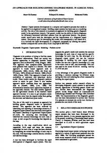
Behavioral Unit (BU): The BU keeps the state and the functionality of the module. The functional description is done by means of a Colored Petri net (CPN). Attributes and methods that operate over the attributes are expressed by means of a Non-Hierarchical CPN. From the structural viewpoint, the BU of an OMCPN is a strict CPN. Interface Module (IM): This is the element responsible for the communication between the BU and the rest of the system. To use an OMCPN module is necessary to invoke one of its services. Only through the IM, other components of the system may have access to the methods and attributes encapsulated inside the module. Moreover, only through the IM, the BU is able to access the services of other BU modules in the system. The IM is an abstract view of the module, hiding internal details of it. Inside the IM there are the name of OMCPN module and methods provided and used. The intuitive interaction model used by OMCPN modules is client-server. Thus, it is expected that after an invocation, the system start an activation of the invocated method. In addition, analogously, after every termination, a return is expected to occur. An example of class model by OMCPN is the Fire detector Class, presented in Figure 10 (a). In this model a token in P1 indicates the smoke sensor status (if est = active, then smoke is detected in the building, if est = inactive then no smoke is detected). The value of est is defined by the action associated with transitions t1 and t2, that are methods called by the Smoke Sensor. Similarly, a token in P2 indicates the status of the temperature (t= normal temperature, t= medium temperature, and t= high temperature). A token in P4 indicates the status of the Fire Controller (F= Fire Controller in stand by (sb), F= Fire Controller controlling fire). Another example of class model by OMCPN is the Ventilation controller, presented in Figure 10 (b). In this model color MSG defines the structure of the messages passed between objects. Color ADD is a pair of sender and receiver identifiers for the message. In this case the ventilator controller class receive messages from fire detector class (FDC) and cooling controller (CC). Fire detector class communicate fire detection (control FD) or normal conditions (sb). When fire detection is activated the ventilator controller class increased the ventilator speed. Cooling controller (CC) to communicate increased (hspd) or decrease (lspd) of the ventilator speed. Fire detector Class (FD)
Ventilation controller Class T12
If est=1 and t ≥ 1 then f = controlFD T1 est
Est = active
P1 est
T2 Est = inactive
est
EST est
f t
f
t t
t = high T5
t
P2
T7 t
MSG
f
TEMP
f
P6
T11 1 P7
P9 P10 MSG
MSG
MSG
T17
T16
t18
MSG
P12
mes
P5 INC
MSG
mes
T9
f
f
mes
f
P4 f
T14 mes T13
T8
INC
T3 t = normal T4 t = medium
INC P3
T6
MSG
P8
T10
P13
MSG
mes
mes
mes
P11
T15
If est=1 and t = 01 then f = sbFD
Color EST = with active | inactive Color TEMP = with normal | medium | high Color INC = with sbFD | controlFD Var est: EST Var t: TEMP Var f: INC
BU
Methods provided Methods used T1 Smoke detected T8 Turn on fire controller T2 No smoke detected T9 Turn off fire controller T3 Normal temperature detected T4 Medium temperature detected T5 High temperature detected IM
Color MSG = product ADD * DAT Color ADD = product ID * ID Color ID = with FD | V | CC Color DAT= with sb | controlFD | hspd | lspd Var mes: MSG
Methods provided T10 Turn on ventilation controller T18 Turn off ventilation controller
BU
Methods used T11 Turn on ventilator T17 Turn off ventilator T12 Set ventilator as high speed T13 Set ventilator as low speed IM
(a) Fire detector Class modeled by OMCPN (b) Ventilation controller Class modeled by OMCPN Figure 10. Class model by OMCPN 2. Formal Analysis In order to use the well-established concepts and powerful analysis methods developed for CPN, it is applyed a systematic way to obtain an equivalent CPN for each PN. Thus, it is used the CPN-Tools and Design/CPN tool to simulate and analyze the PN system. Basically, the models consider a scenario and they are analyzed using the occurrence graph (OG) to study the detection of deadlocks, or forbidden states in the model. An initial marking represents the initialization of the execution of an OMCPN with a selected method.
Based on the simulation and the occurrence graph it was verified properties that help the design of the system. An example is the verification of the fire strategy of the HVAC system. 5. Conclusion This work proposes an open distributed systems approach for building automation. The innovative point of the approach is the synergetic merging of ODP, UML and Petri net. The ODP viewpoints guide the design process. By using UML the object-oriented aspects of the system are highlighted through the different diagrams, while a formal representation of the system is provided by the use of Petri net. The viewpoints considered in this work were enterprise, information and computational. They represent a particular abstraction of the system. For modeling the viewpoints, the UML and Petri net were used. The UML was useful to structure the modeling process according to the viewpoints and the Petri net were used for formal modeling and analysis of system. Thus, the proposed approach is benefit from a graphical notation as well the use of the ODP, allowing a better control of the modeling process because the use of different level and views. Once the models have been analyzed, the approach should be translated into a programming language code in order to be implemented. Future directions of this work must contemplate a complete methodology for the building automation design that consider its implementation using engineering and technology ODP viewpoints. 6. Acknowledgements The authors gratefully acknowledge the financial support to the present project of the Brazilian Governmental Agencies CNPq, CAPES, FAPEAM and FAPESP particularly, the authors would like to thank TIDIA / KyaTera program under which the works is developed. 7. References Baresi, L. and Pezzè, M., 1998, “On formalising UML with high-level Petri nets”, Concurrent Object-Oriented Programming and Petri Nets, Lecture Notes in Computer Science, pp. 42-55 Springer Verlag, Berlin. Booch, G., Rumbaugh, J.and Jacobson, I., 1998, “The Unified Modelling Language User Guide”, Addison-Wesley Longman, Inc. Harlow, England. Callaghan, V., Clarke, G., Colley, M. and Hagras, H., 2001, “A Soft Computing DAI architecture for intelligent buildings”, Journal of Studies in Fuzziness and Soft Computing on Soft Computing Agents. Physica-VerlagSpringer. Berlin. Faroqui, K., Logrippo and L. Meer, J., 1995, “The ISO reference model for open distributes processing: an introduction”, Comp. Nets. and ISDN Systems 27, pp.1215-1229. Gaspoz, J. P., 1996, “Methodology for the development of distributed telecommunications services”, Journal Systems Software 33, pp. 253-271. Giese, H., Graf, J. and Wirtz, G., 1999, “Closing the gap between object-oriented modelling of structure and behaviour”, Proceedings of the Second International Conference on the Unified Modeling Language, Colorado, USA. ISO/IEC., 1995, “Open Distributed Processing -Reference Model Part 3: architecture”, International Standard. Katchabaw, M.J., Howard, S.L., Lutfiyya, H., Marsahall, A.D., Bauer, M.A., 1999, “Making distributed applications manageable through instrumentation”, Journal of Systems and Software 45, pp. 81-97. Pianegiani, F., Macii, D., Carbone, P., 2002, “Open distributed control and measurement system based on an abstract client-server architecture” Virtual and Intelligent Measurement Systems, VIMS '02. 2002 IEEE International Symposium, pp.63 – 69. Wang, S. and Xie, J. 2002, “Integrating Building Management System and facilities management on the Internet” Automation in Construction, Volume 11, Issue 6, October, pp. 707-715. OMG UML 2 2003 Infraestruture Final Adopted Specification. Object Management Group. Wong, J.K.W., Li, H and Wang S.W., 2005 “Intelligent building research: a review” Automation in Construction, Volume 14, Issue 1, January, pp. 143-159. 8. Responsibility notice The authors are the only responsible for the printed material included in this paper.