Development of Bayesian Networks from Unified Modeling Language Artifacts Philip S. Barry
Peggy S. Brouse
Dept. of Systems Engineering
Kathryn Blackmond Laskey
The MITRE Corporation
Dept. of Systems Engineering
George Mason University
1820 Dolley Madison Blvd.
George Mason University
Fairfax, VA 22032-4444
McLean, VA
[email protected]
examines
from
how
Bayesian
development
Unified
Process.
Process
models
The the
Networks
artifacts
Unified
relationship
can
intrinsic
Software
in
be the
Development
between
requirements in the Use-Case model.
functional
These relationships
are expanded in the Analysis Model and a clear mapping to
design
components
is
created.
By
exploiting
the
relationships intrinsic in the Use-Case Model, as well as the stereotypical classes and temporal ordering found in the
[email protected]
effort and often stage the design and implementation of
paper
generated
Fairfax, VA 22032-4444
[email protected]
Abstract This
22102-3481
analysis
model,
Bayesian
networks
system requirements can be generated.
that
represent
These networks
key
features
to
meet
release
schedules
and
budgetary
constraints. In practice, determining which Use-Cases are architecturally significant and how they may relate to other
Use-Cases
as
well
as
additional
system
requirements is usually determined by heuristic methods. We assert by exploiting the implicit structure in UML diagrams
an
algorithmic
and
mathematically
sound
method can be introduced to understand the importance of use requirements represented as Use-Cases as well as the system requirements they imply.
can then be used to model and assess the architectural
2
impact of the requirements early in the system lifecycle,
According to Ivar Jacobson [12] “it is absurd to believe
thus
promoting
design process. design
also
a
more
efficient
and
effective
system
Formal capture of requirements during
promotes
reusability
of
design
knowledge
across similar system.
1
systems
“The system shall…”. led
to
a
search
The futility of direct specification
for
more
human-friendly
ways
to
A highly promising and
popular approach is to develop requirements from a set of engineering
requirements
essential
to
it
is
analysis
development
reliable systems [4].
well
and
of
recognized
that
documentation
high
performing
is
and
This is equally true in software
engineering, where requirements management is generally recognized as a key indicator of organizational maturity [18].
relevant list of thousands of requirements of the form
develop system requirements.
effective
the
The Requirements Side of UML
that the human mind can come up with a consistent and
has
Introduction
Within
Use-Cases:
Methodologies for developing and documenting
software requirements [e.g., 8,11,19,21] have proliferated in the literature and have been employed with varying
Use-Cases.
Use-Cases
represent
functionality
of
the
system in terms of prototypical problems or processes the system
is
expected
to
execute.
Thus,
a
Use-Case
represents one distinct way of using the system from a given
external
generally
agent
or
specified
actor’s
using
a
view.
Use-Cases
graphically
are
based
methodology for defining the actions the system is to perform.
Analyzing
the
functionality
needed
for
successful execution of the Use-Case then derives system
degrees of success.
requirements.
The Unified Modeling Language (UML) [5] is rapidly
A Use-Case specifies a primary sequence of actions the
becoming the de facto standard for analysis and design within
the
provides
a
software
development
diagrammatic
requirements,
which
community.
approach
begins
with
to
describing
Use-Cases
and
UML user then
leads into more formal specification using stereotypical classes
in
an
analysis
model.
Key
elements
of
these
artifacts form the basis for architectural views into the system as well as providing the groundwork for design, implementation and validation and verification.
system is to perform, and may also include excursions from the main sequence.
Use-Cases have operations and
attributes. Thus, a Use-Case description can include state chart diagrams, collaborations and sequence diagrams. Use-Case attributes represent the values that a Use-Case instance uses and manipulates.
Use-Case instances do not
interact with other Use-Case instances because by design Use-Case models should be simple and intuitive.
The
flow of events and special requirements are captured in special textual descriptions.
From an architecture viewpoint, all Use-Cases are not equally important, necessitating the need to develop a
2.1
scheme to prioritize the most significant Use-Cases.
System designers can specify relationships between Use-
This
need comes from the requirement to focus the design
Structuring the Use-Case Model
Cases. These relationships can be used to form interesting
structures that can provide evidence to the importance of
system requirements contingent upon an agent’s goals is
requirements
often referred to as allocation and flowdown [9].
based
upon
their
relationships
to
other
requirements. There are three relationships used to model
We
Use-Cases:
from a computational mechanism to represent of system
generalization, extension and inclusion.
suggest
that
Generalization inheritance.
•
between
Use-Cases
Use-Cases
can
is
perform
a
all
kind
of
behavior
benefit
that engender them. To achieve this the relationship we define
an
abstract
interrelated
system
SRW is a directed graph in which the nodes represent
of actions.
system requirements and the edges represent relationships
These additions are contingent upon some
A
between requirements that we call weak implication. We
Inclusion between Use-Cases models the situation
say that one node weakly implies another node if it is
where
more
the
including
Use-Case
cannot
function
likely
second
that
node
requirements within
Within the Unified Software Development Process [12], analysis is used to address previously unresolved issues by analyzing the requirements in depth.
Key to analysis
is the development of the analysis model, which yields a more
precise
specification
of
the
resulted from the Use-Case model. described
introduce
in
more
the
language
formalism
of
and
requirements
than
As the analysis model the
can
developers be
used
about the internal workings of the system.
to
it
can
reason
The analysis
model can be considered a first cut at a design model and is an essential input to system design and implementation. The analysis model makes use of a number of diagrams. Of particular interest is the collaboration diagram, which describes
how
performed. analysis
a
specific
The
stereotypical
analysis
objects.
Use-Case
diagram
is
classes
These
is
drawn and
objects
realized in
their
focus
and
terms
of
instantiated on
handling
functional requirements and postpone the consideration of nonfunctional
requirements
by
designating
them
as
special requirements.
there are three stereotypical classes: boundary classes, entity classes and control classes. Boundary Classes are used
to
model
interaction
between
the
system
and
its
actors, e.g., information input and output and can be used to clarify system boundaries. Entity Classes are used to model information that is long-lived and persistent, which have
associated
behaviors
and
a
logical
data
structure. Control Classes are used to model coordination, sequencing, transactions and control of other objects.
system is the understanding of the relationships between
requirements
requirements. is
the
are
if
trigger
a
providing
the flow
a
represented
first of
model
one
weak for
by
is.
the
User
implication
allocation
and
demonstrated
that
flowdown of requirements. Previous
work
by
the
authors
has
Bayesian networks provide a natural computational model for SRWs
[2,3].
A Bayesian network is both a structured
representation for knowledge about the interrelationships among
uncertain
architecture
for
variables
reasoning
and
about
a
computational
these
variables.
A
Bayesian network is a directed graph composed of nodes and arcs.
The nodes represent variables whose value is
uncertain and the arcs represent dependency relationships between the variables.
In our application, the uncertain
variables represent requirements and the arcs represent weak implication.
A requirement can be in one of two
states: implied or unimplied (the semantics of these terms is described below). Conditional probabilities are used to model
the
strength
of
the
relationship
between
the
associated variables. As
a
computational
architecture,
a
Bayesian
network
allows the user or application to declare “evidence” on
result
often
In
of
addition,
user
generated.
needs, This
if
accumulation,” compute revised probabilities for all other nodes in the network.
a
other
system system
expansion
of
In the present application context,
user requirements can be declared as “evidence” in an SRW represented as a Bayesian network.
This evidence
propagates through the SRW via the weak implication links,
resulting
in
updated
probabilities
for
other
requirements in the SRW. Not only are Bayesian networks a useful visual metaphor to
aid
in
problem
Key to fully understanding the requisite functionality of a
requirement
requirement
needed
can
SRW,
the
appropriately
Bayesian Networks for Requirements
system
a
the
is
some of the nodes and, through a process called “evidence
In the analysis phase of the Unified Development process,
the
of
Extension models additions to a Use-Case’s sequence
Analysis Models
may
structure
requirements called a system requirement web (SRW).
without the included Use-Case.
4
can
described in the generalizing Use-Case.
conditions being satisfied.
•
is
engineering
requirements to each other and to the user requirements
•
3
requirements
at
construction
represent hand.
a
At
of
semantics any
SRWs,
they
appropriate
given
moment
to in
also the the
requirements definition process, the currently operating Bayesian network represents a set of requirements, some declared as implied, some undeclared, and possibly others declared
as
unimplied.
After
evidence
accumulation,
each node in the network carries an associated probability that
it
is
implied
given
the
current
set
of
declared
evidence.
All
unimplied
have
requirements
respectively. intermediate
declared
probabilities
All
of
undeclared
probabilities.
as
implied
unity
or
requirements
Mathematically,
or
zero, have
the
belief
propagation algorithm calculates for each requirement the probability it is implied given the current declared set of implied and unimplied requirements. the
current
represents
probability the
necessary
that
probability
element
of
a
Semantically, then,
requirement
that
this
is
implied
requirement
functionality
in
a
is
system
a
that
satisfies the functionality represented by the declared set. Declaring
new
requirements
as
either
implied
or
unimplied initiates a new evidence accumulation cycle that
results
in
revised
probabilities
requirements.
This
mechanism
exploring
for
formalism the
is
a
for
undeclared
powerful
design
interrelationships
among
requirements. Especially
important
among requirements.
to
the
requirements
definition
An attempt to specify incompatible
requirements results in an error condition in the associated Bayesian network.
Evidence accumulation generates an
error condition when the pattern of evidence is logically impossible according to the model.
When inconsistencies
are discovered, this means the associated requirements are Bayesian
given
the
network.
constraints
When
this
represented
occurs,
the
in
the
software
engineer can explore ways to adjudicate the conflict by use
of
a
feature
evidence.” varying
Mapping Use-Case Models to Bayesian
Networks As discussed, Use-Cases represent the external function view
of
user
of
Bayesian
networks
called
“soft
Soft evidence allows the engineer to declare
degrees
of
strength
requirement is implied.
with
which
a
given
user
Requirements deemed essential
can be declared as hard evidence; requirements deemed less than essential can be declared as soft evidence with strengths
related
to
outright
conflicts
their are
perceived
importance.
discovered,
the
declarations can be relaxed to soft evidence.
If
offending Varying the
strengths of the soft evidence declarations could be an
requirements
and
collaboration
elicitation
involves
an
element
of
actual need has been captured. relate
uncertainty
that
fall
short
of
outright
inconsistencies
and
to
find
clusters of requirements responsible for the conflict.
when
we
transform
them
into
diagrams.
the
requirements
Representing this uncertainty becomes very
models
such
SRW
broke
up
fragments
the that
larger
SRWs
into
corresponded
to
We
manageable a
potentially
conflicting
requirements
ability of the unaided human mind.
these fragments, different views into the domain could be created,
emphasizing
important to the analyst.
particular
aspects
that
explicitly
SRW chunks was labeled gluing.
Laskey and Mahoney
then
models
this
overwhelms
the
uncertainty
between
the
requirements as represented by Use-Cases and elements of
collaboration of
diagrams.
evidence
Contingent
such
as
the
upon
importance
the of
a
given actor, a quantitative assessment can be made as to how strongly we believe the requirement is indicated, or, in the parlance of SRWs, implied.
We therefore see the
ability to translate Use-Case models and their associated collaboration
diagrams
into
Bayesian
networks
as
important potential advance in software engineering. SRW
provides
a
way
of understanding
an
The
the degree to
which each of the specified requirements is implied by the information
encoded
in
the
user
requirements.
This
ability to represent degrees of implication is key to the identification
and
effective
management
of
conflicts
among requirements.
5.1
Generalization
A generalized Use-Case contains common functionality that is allocated to all specializing Use-Cases. Mapping the
generalization
relationship
fragments is straightforward.
to
Bayesian
network
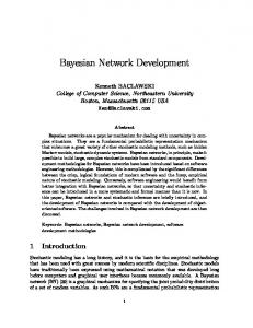
Consider Figure 5.1, where
Use-Case A is a generalization of Use-Case A1 and UseCase A2.
We view this as functional requirements A1
and A2 being specializations of functional requirement A.
Use Case Model
Use Case A
Use Case A2
Bayesian Network Fragment Requirement
were
The process for combining the
and
collaboration
A Bayesian network
natural
decomposition of the domain of interest. By combining
as
important when there the sheer number of interrelated and
In previous work [2], it became apparent that the behavior therefore
the
introduced
Use Case A1
of large SRWs was often difficult to predict and test.
that
Further uncertainty is
important sensitivity analysis tool in the design process. Conflict metrics [13, 16] can be used to identify conflicts
diagrams
specify the top-level system functionality. Requirements
introduction
process is the ability to identify and adjudicate conflicts
incompatible
5
A1 Requirement A
Requirement
took a similar approach by using network fragments to
A2
model situation assessment [17]. Figure 5.1
Generalization Mapping
This translates into a Bayesian network with an analogous structure.
The direction of implication flows from A to
A1 and A2 reflecting a top-down decomposition.
Use Case Model
This
indicates that one is more likely to encounter the general case than the specific requirement.
Use Case A1
Thus: Use Case A
P(A) = prior P(A1 | A) = P(A |A1)P(A1) / P(A) P(A2 | A) = P(A |A21)P(A2) / P(A)
5.2
Inclusion
Bayesian Network Fragment
Inclusion models the situation in which a Use-Case is composed of a number of sub-Use-Cases.
Requirement
inclusion, the top-level Use-Case cannot execute without the execution of one of the sub-Use-Cases.
Requirement A1
In the case of
A
To see how
Additional
this can be translated to Bayesian Network fragments, consider Figure 5.2.
Use-Case A is related to Use-Case
A1 and Use-Case A2 by an inclusion relationship. more
likely
that
the
need
for
Use-Case
A
It is
would
Figure 5.3:
be
elicited in a requirements generation activity, so we draw the implication arrow from Use-Case A to Use-Case A1 and Use-Case A2.
Criteria
Thus, the probability assignments for
the nodes are as before:
Consider
the
Figure 5.3.
general
Extension Mapping
case
shown
diagrammatically
This models the situation where some additional criterion triggers Use-Case A1 after Use-Case A executes.
P(A) = prior
in
Use-Case A is extended by Use-Case A1. The
additional criterion is described in the textual flow of
P(A1 | A) = P(A |A1)P(A1) / P(A)
events
P(A2 | A) = P(A |A21)P(A2) / P(A)
write-up.
Requirement
A1
This implied
situation by
is
modeled
Requirement
A.
as The
additional criterion is modeled as another requirement node.
Use Case Model
Use Case A1
The direction of implication is from the additional
criteria (AC) to requirement A1.
P(A1 | A, AC) = P(A|A1, AC)P(A1|AC) P(A|AC)
Use Case A
Use Case A2
Thus:
6
Exploiting the Analysis Artifacts
The analysis process is a refinement and a specification of the Use-Cases into a more formal language.
Baysian Network Fragment
Use-Case, Requirement A1
specifies
an in
analysis
generic
model
terms
the
can
be
For each
created
system
which
functionality.
Analysis models are formed from the instantiation of the
Requirement
stereotypical classes.
A
Requirement A2
Figure 5.2:
6.1 Collaboration Diagram Mappings
Inclusion Mapping
A collaboration diagram is the functional specification of an individual Use-Case using instantiated objects from the stereotypical
classes,
shown
in
Figure
6.1.
The
collaboration diagram relates the objects by links that
5.3
represent messages sent between the objects.
Extension
Extension models the case where a given Use-Case will branch into additional behavior given the satisfaction of some condition or conditions.
In the case of extension,
the first Use-Case does not need the additional Use-Case to execute.
The second Use-Case represents exceptional
behavior if conditions are met.
are
numbered,
representing
a
rough
The links
ordering.
The
messages model requests for services from the sending object to the receiving object.
These messages provide a
finer view of the functionality offered by a given object.
Rule 3: If I(C, di) = C, we write a requirement for functionality of type C
Stereotypical Analysis Model Classes
acting on information di.
This is represented as a like named
node in N.
Entity Class
Rule 3.1: If a message mi is sent to a control object C from another object O, we write a requirement for functionality M from object C.
Boundary Class
This is represented as a like named node M in the BN with an arc drawn from C to M.
We further draw an arc from the like
named node in the BN, which represents O to M.
Control Class
6.2
Prior and Conditional Probability
Assignment Represent as a requirement (node
A key step in the process of building a Bayesian network
in the BN) for persistent storage
model is assigning the local probability tables associated with the nodes.
Represent as a requirement for
Represent as a requirement for
data is available.
represents internal business logic this can be broken down into lower
In [2, 3] we found that heuristic probability assignment
level control classes
provided good results. specification
Stereotypical Analysis Classes
fragments
of
and
We used heuristics both for the
probability
the
tables
combination
in
of
individual
tables
nodes when fragments were combined. Collaboration diagrams are readily mapped into network fragments.
Let a collaboration diagram D consists of
three stereotypical classes B , C Control
and
Entity.
Let
and
function
I
E
for Boundary,
be an instantiator,
which can create objects instantiated from these classes. For example, I(B, d) = B would indicate that a boundary object
has
been
created
additional data d. the
in
a
way
that
depends
on
Let O consist of all of the objects in
collaboration
diagram
that
have
been
instantiated.
Thus, O = { I(B, d), I(E, d), I(C, d) } where d = {d1, d2, d3…dn}
and
∈
O
O.
With these assumptions, several
mapping rules can be readily written.
types
of
influence
additive
heuristic
This is
Rule 1.1: requirement
for
message
of
functionality
mi
type from
mi
to
B,
object
we B.
write This
a is
represented as a like named node M in the BN with an arc drawn from B to M.
the
a
instance
where
an
of
the
requirements
in
the
Taking away any one
parent
group
undermines
support for the requirement they together imply.
The
“noisy or” model was used in the case where each parent alone weakly implies the associated requirement (i.e., the weak
implication
is
an
“or”
relationship).
A
good
discussion of the “noisy or” distribution is provided in
concern
network
in
the
automated
fragments
is
the
generation
explicit
independence
of
Bayesian
introduction
between
of
requirements,
particularly when translating collaboration diagrams.
For
example, by rule 1.1 specified in Section 6.1 above, if an actor
sends
becomes
a
a
message
to
requirement
a
boundary
indicated
by
object an
B,
arc
that from
requirement for the boundary object to the requirement
Rule 1.2: We model the Actor A as evidence for requirement M. Rule 2: If I(E, di) = E, we write a requirement for persistent storage of type E containing information di.
This is represented as a like
named node in N.
for the functionality represented by the message, say M1. If a second message is sent to B, a second requirement is indicated
and
requirement
If a message mi is sent to an entity object E from another object O, we write a requirement for functionality M from object E.
This is represented as a like named node M in the BN with an We further draw an arc from the like
named node in the BN that represents O to M.
an
arc
M2.
independence
Rule 2.1:
arc drawn from E to M.
in
implication is a “and” relationship).
conditional
a
used
used,
The linear
more different requirements in combination (i.e., the weak
represented as a like named node in SRW network fragment N. sends
were
individual requirement is indicated by a group of two or
A
B which interacts with the actor for data of type di.
A
is
SRW
common
Specifically, two
methods
linear additive heuristic and the “noisy or”.
If I(B, di) = B, we write a requirement for actor interface of type
Actor
combination
for
[14].
Rule 1:
If
In
requirements engineering, it is rarely the case that such
high level functionality - usually
Figure 6.1:
The ideal situation would be to have
frequency data from which to estimate likelihoods.
interface to a specific actor
is
This
drawn is
relationship
from
modeled in
the
as
B a
to
the
new
conditional
Bayesian
Network,
where both the probability that M1 is really needed and the probability that M2 is needed are dependent upon the probability that B is indicated, but are independent of each other given B.
Should it be known with certainty
whether B is actually indicated, any additional evidence
functionality
for M1 will not effect the certainty of M2 or vice versa.
Selected Products,
of
Select
Products
requiring
Add Selected Products
and
Display Remove
Selected Products. In general, we believe that we can make the assumption of
conditional
independence
because
we
are
taking
advantage of the precedence relationships between the stereotypical classes and their associated functionality. the
example
above,
if
we
know
with
certainty
In
that
a
Browse Products
Log on
boundary object is not required, both M1 and M2 become (absent other evidence) improbable and independent of each other.
Browse w/ Search Criteria
That is, evidence for M1 would not affect the
probability that M2 is implied, absent the existence of a requirement relating the two.
that a boundary object is required, M1 and M2 become probable and independent of each other. that
M1
is
actually
not
Select Products
Conversely, if we know
required
Again, evidence
would
not
affect
Remove Selected
Display Selected
Buyer
Products
pbdog.com
Products
Add Selected
the
Products Provide FAQs
probability that M2 is required if that evidence did not cast doubt on the requirement for the boundary class. Rather, such evidence would indicate the existence of
Provide Index Help
some alternate way to satisfy the role that functionality
Provide On-Line Help Purchase Products
represented by M1 plays in the boundary class.
7
Figure 7.1:
A Mapping Example
To illustrate the ideas discussed in the previous section, consider the following example.
Suppose a requirement
elicitation activity has determined that there is a need to develop
an
purchase
application
products
over
that
allows
the
an
Internet.
individual A
number
to of
functional requirements have been defined, such as log on to the site, browse products, select products, etc. 7.1
shows
the
list
of
requirements
necessary
Table
for
this
system.
Purchase Using Credit Card
Top-Level Use-Case Model
Figure 7.2 represents a collaboration diagram for the UseCase
Purchase
stereotypical messages
Using
analysis
from
the
Credit
Card
classes. actor,
stereotypical classes.
developed
Notice
as
well
the
as
with
addition
between
of the
These will form the basis for the
functionality specified in the Bayesian network.
While a
loose temporal ordering is suggested by the numbering of the messages, sequencing requirements are not explicitly modeled with this diagrammatic technique but rather are
• Provide Index Help • Log on • Browse products • Browse with search criteria • Select products • Display selected products
shown by interaction diagrams, which are not examined
• Add selected products • Remove selected products • Provide On-line Help • Provide FAQs Purchase
here.
Products
• Purchase using Credit Card • Purchase Products
3. Get
:Order
4. Get
:Credit Card Validation
Total
Table 1:
On-Line Product Purchase Functionality List
5. New 2. Send credit card info 1. Input order
The decision is made to refine the textual descriptions of functional requirements by creating a top-level Use-Case model, provided as Figure 7.1. computer,
named
Handler 7. Request Purchase
In the figure, two actors
are identified, namely the buyer of the product and the company
:Request
information
pbdog.com.
The
Figure
6. Purchase : Buyer
Request
shows the association between the Use-Cases and the the
UI
In
particular,
the
requirement
of
:Financial Data Document
10. New
:Purchase 9. Get
:Order Handler
actors, as well as the relationships of generalization and inclusion.
8. Get
: Dog Food Order
Browse
w/Search Criteria has been identified as a generalization
:Order Details
of browse products, Provide On-Line Help generalizes Provide FAQs
and
Provide Index Help and P u r c h a s e
P r o d u c t is a generalization of Purchase Card.
The
inclusion
relationship
is
Using
illustrated
Credit by
the
Figure 7.2:
Collaboration diagram with Stereotypical Classes
Figure 7.3:
Bayesian Network from Use-Case Model
Figure 7.4:
Bayesian Network Fragment from Collaboration Diagram
Once
the
Use-Case
models
and
the
collaboration
diagrams have been created, it is straightforward to create the structure of the Bayesian Network using the rules described
in
Sections
5
and
6
above.
Figure
7.3
8
Implementation Architecture
The
real
power
represents the Bayesian Network constructed from the
transformation
Use-Case model shown in Figure 7.1.
Network
Notice how the
conditional independence has been directly modeled by application
of
the
rules
Add_Selected_Products Remove_Selected
as
stated.
For
conditionally
Product
Select_Product. standpoint,
is
given
the
example,
independent
requirement
of for
This is reasonable from a requirements
for
if
it
is
known
that
functionality
Select_Product is definitely not needed, any evidence for Add_Select_Products
fragments
this
approach
UML
that
are
is
diagrams then
glued
transparent
into
Bayesian
together
with
minimal user intervention. At the time of this writing, we are focusing on implementing the building blocks for this transparent translation.
We are using Rational Rose
TM
to
develop Use-Case models and collaboration diagrams in UML.
These models are saved in *.mdl format, which is
human readable text.
A parser has been written which
extracts the relevant information and sends it to an expert
b y
system that applies rules discussed in Sections 5 and 6.
Remove_Selected_Product can be reasonably discounted.
The expert system, written using Jess [10], outputs text
Similarly, if Select_Product is definitely indicated, it is
files in Bayes Interchange Format (BIF) which represent
reasonable
Bayesian Network fragments.
to
state
Add_Select_Products reasonably
p r o v i d e d
of
from
is
that
the
evidence
compelling
disregard
and
we
information
for can from
Remove_Selected_Product. Figure
7.4
represents
a
can Bayesian
network
fragment
developed to represent the collaboration diagram shown in Figure 7.2. 7.1,
a
For each Use-Case represented in Figure
collaboration
Currently, both JavaBayes [7] and the BOSH prototype
diagram
was
developed.
These
read
the
XML
BIF
files.
JavaBayes
is
together, as well as interpret the effect of nonfunctional requirements and other evidence on the glued network. BOSH,
introduced
in
[1],
is
a
prototype
agent-based
expert
network, wholly replacing the Use-Case node from which
evidence from a user requirements specification.
it
uses APIs from both JavaBayes and JESS.
has
been
derived.
As
mentioned,
the
collaboration
accordingly. truly
Conditional
are
reallocated
The glued Bayesian network then more
represents
functionality
probabilities
the
based
relationships upon
the
between
belief
that
system
the
user
requirements are truly needed, which are contingent upon the importance of the user.
system
that
infers
system
requirements
given BOSH
The common
nodes are identified and used as the basis for gluing the fragments.
to
The
BOSH prototype is used to glue the network fragments
diagrams can then be glued into the higher level Bayesian
diagrams contain common functionality.
used
visually inspect and debug the network fragments.
Implementation insight for
We are beginning work on two improvements that will generalize the applicability of the prototype.
First, the
XMI toolkit from IBM [6] provides an API that will read Rational Rose files and translate them into XMI format. We are rewriting the parser to read XMI files, so the system will work with any software that can output XMI as opposed to just one product.
The second improvement
pasting hierarchical Bayesian networks is provided in the
is more significant, and involves totally encapsulating the
object oriented Bayesian Network literature [15, 20].
implementation of the Bayesian network within the UML diagrams.
9
[6] Brodsky, S., “
Summary and Outlook
The Unified Software Development process provides a traceable
methodology
for
system
development,
iteratively improving on each of the specified software artifacts.
In
this
paper
we
have
suggested
that
augmenting the requirements specification process with Bayesian Networks provides an algorithmic approach to modeling
the
relationships
between
user
and
system
requirements, as well as determining their architectural significance.
We assert that a fuller understanding of the
requirements space allows for more effective design and implementation decisions as well as project planning.
confirm functional requirements with the user and to then put those requirements in a form that can be used by the This
transformation
from
functional
requirements to formal requirements usually introduces errors.
After problem analysis and the creation of Use-
Cases, which are validated with the user, a transformation must occur to a formalism that is not easily validated with the user. suggested
If the analyst is given a tool such as we have herein,
we
believe
this
transformation
will
result in considerably less error.
UML
temporal
than
discussed
in
considerations,
this
which
paper. may
For
be
example,
found
interaction diagram, have yet to be examined.
in
an
Similarly,
we have not looked at nonfunctional requirements that might
be
found
in
deployment
diagram.
The
full
integration of these additional types of requirements using Bayesian
Network
fragments
is
an
exciting
area
of
research that is yet to be explored.
http://www.cs.cmu.edu/~javaBayes/index.html/. [8] Darimont, R. and van Lamsweerde, A.
“Formal
Refinement Patterns for Goal-Driven Requirements Elaboration”, Proceedings of the Fourth ACM Symposium on the Foundations of Software Engineering (FSE4), San Francisco, Oct. 1996. [9] Dorfman, M.
“Requirements Engineering”, in nd
Edition, Thayer,
R. and Dorfman, M. editors, IEEE Press, Los Alamitos, CA, 1997. [10] Friedman-Hill, Ernest.
JESS source code and
documentation available at http://herzberg.ca.sandia.gov/. [11] Jackson, M.A.
System Development. Prentice Hall
Inc., Englewood Cliffs, NJ, 1983. [12] Jacobson, I., Booch, G. and Rumbaugh, J.
The
Unified Software Development Process. Addison-Wesley Publishing Company, Reading, MA, 1999. [13] Jensen, F.V., Chamberlain, B., Nordahl, T. and Jensen, F.
“Analysis in HUGIN of Data Conflict” .
Artificial Intelligence",
Elsevier Science Publishing
Company Inc., New York, NY 1991. [14] Jensen, F.V.
An Introduction to Bayesian Networks.
Springer-Verlag New York, 1996. [15] Koller, D. and Pfeffer, A. “Object-Oriented Bayesian Networks”. "Proceedings of the Thirteenth Conference on Uncertainty in Artificial Intelligence," Morgan Kaufmann Publishers, Inc., San Francisco, 1997. [16] Laskey, K. “Conflict and Surprise: Heuristics for Model Revision "Proceedings of the Seventh Conference
[1] Barry, P., An Agile Approach to Requirements Modeling, Ph.D. Dissertation, George Mason University, Fairfax, Virginia, May 1999. “An Application of
Uncertain Reasoning to Requirements Engineering”. "Proceedings of the Fifteenth Conference on Uncertainty in Artificial Intelligence”, Morgan Kaufmann Publishers, Inc., San Francisco, 1999. [3] Barry, P., Laskey, K. and Brouse, P.
“Modeling the
Requirements for Enterprise Control Systems”, Proceedings of the DARPA-JFACC Symposium on Advances in Enterprise Control, November 1999. [4] Blanchard, B. and Fabrycky, W., Systems Engineering and Analysis, Third Edition.
JavaBayes source code and
documentation available
on Uncertainty in Artificial Intelligence",
References
[2] Barry, P. and Laskey, K.
[7] Cozman, Fabio.
"Proceedings of the Sixth Conference on Uncertainty in
There are significantly more diagrams and views provided by
4.ibm.com/software/ad/standards/xmiwhite0399.pdf.
Software Requirements Engineering, 2
One of the challenges in requirements engineering is to
designer.
XMI Opens Application Interchange”,
http://www-
Prentice Hall, Upper Saddle
River, NJ, 1998. [5] Booch, G., Rumbaugh, J. and Jacobson, I.
The
Unified Modeling Language User Guide. AddisonWesley Publishing Company, Reading, MA, 1999.
Morgan
Kaufmann Publishers, Inc., San Mateo,California 1991. [17] Laskey, K. and Mahoney, S.,
“Network Fragments:
Representing Knowledge for Constructing Probabilistic Models”.
"Proceedings of the Thirteenth Conference on
Uncertainty in Artificial Intelligence," Morgan Kaufmann Publishers, Inc., San Francisco, 1997 [18] Paulk, M., et.al., The Capability Maturity Model Guidelines for Improving the Software Process. AddisonWesley Publishing Company, Reading, MA, 1995. [19] Peterson, J.L., Petri-Net Theory and the Modeling of Systems. Prentice-Hall, Englewood Cliffs, NJ, 1981. [20] Pfeffer, A., Koller, D., Milch, B. and Takusagawa, K.
“SPOOK: A System for Probabilistic Object-Oriented
Knowledge Representation”.
"Proceedings of the
Fifteenth Conference on Uncertainty in Artificial Intelligence," Morgan Kaufmann Publishers, Inc., San Francisco, 1999. [21] Rumbaugh, J. et. al., Object-Oriented Modeling and Design. Prentice-Hall, Englewood Cliffs, NJ, 1991.