1st International Conference on Sensing Technology November 21-23, 2005 Palmerston North, New Zealand
Development of Docking System for Mobile Robots Using Cheap Infrared Sensors K. H. Kima, H. D. Choia, S. Yoona, K. W. Leea, H. S. Ryub, C. K. Woob, and Y. K. Kwaka, * a Department of Mechanical Engineering Korea Advanced Institute of Science and Technology, Daejon, South Korea *
[email protected] b LG Electronics Co.
Abstract More and more researches on household mobile robots are being undertaken these days. Since commercial cleaning robots are now available for sale to the public, robots are being used in private homes. As the quality of household robots improves, docking stations, which have a variety of uses, including as automatic recharging ports, have become increasingly important. Generally in household robots, cheap infrared sensors are adopted as part of a homing system that is utilized in conjunction with a docking station, enabling the robot to approach and enter the dock successfully. However, systems that use cheap sensors cannot reach their full potential unless they also have a relatively accurate docking system. In this paper, we propose a homing system that utilizes cheap infrared sensors but that can operate in a broad region, and we suggest a passive docking mechanism that can compensate for docking errors. Experimental results using the proposed system show that the robot is able to home in at a radius of up to 2 m around the docking station. Also, the docking mechanism is able to compensate for an offset error of ±5 cm and an angle error of ±30°, and the probability of docking successfully on the first attempt is over 95%.
Keywords: mobile robot, docking, homing, cheap infrared sensor 1
docking over the course of a week using a robot similar to the Pioneer are described.
Introduction
Recently, many researches on household mobile robots, especially cleaning robots, have been published. Now that commercial cleaning robots such as RoombaTM, from iRobot Co., and TrilobiteTM, from Electrolux Co., have been put on the market, robots are being purchased for use in private homes. These robots are popular with consumers because they are cheap, compact, and multi-functional. As household robots evolve, docking stations are needed for various purposes. Automatic recharging, just one function of the docking station, is essential for achieving long-term autonomy. Oh et al. [1] proposed a method for automatically recharging the batteries on a mobile robot, the Nomad XR4000. The robot and the recharging system use a large number of expensive sensors such as Sick Laser Range Finder, IR and sonar sensors, and a long-range IR beacon constituting a complex IR LED array. The docking station presented by Silverman et al. [2] consists of a stationary docking station and a docking mechanism mounted to a Pioneer 2DX robot. This system also uses sensors such as a laser rangefinder and a color camera to locate the docking station. In [3] and [4], Hada et al. developed recharging capabilities to achieve long-term autonomous mobile robot control. In this paper, the results of repetitive
Colens [5] proposed a system of guidance and positioning relative to a fixed station for an autonomous mobile robot, utilizing a narrow directional infrared beam. The system is simply implemented but other infrared beams must be used to find the narrow beam. For commercial cleaning robots, cheap infrared sensors are usually adopted for use with a homing system that allows the robot to dock at the docking station. The homing systems for commercial robots often suffer from a simple capability and from an inability to overcome docking errors. So, for use with cheap sensors, a relatively accurate docking system is needed. In this paper, we propose a homing system that utilizes cheap infrared sensors but that can operate in a broad region, and a passive docking mechanism that can compensate for docking errors. In section 2, the homing system and the docking mechanism are simply described as an outline of the overall docking system. In section 3, the idea and algorithm of the homing system are explained. In section 4, experimental results using the proposed system are presented and, finally, in section 5, a summary of this paper is presented.
287
1st International Conference on Sensing Technology November 21-23, 2005 Palmerston North, New Zealand
2
Docking System
A docking system is used to implement various functions, such as automatic recharging. The proposed system is composed of a homing system and a docking mechanism, and most of the system, except for the infrared sensors and controller, is embodied in the docking station. When the robot is located within the designated boundary of the docking station, the homing system can direct the robot to move to a location just in front of the docking station. Despite its simple structure, the proposed system can operate in a broad region using cheap IR LEDs and sensors. The docking mechanism can compensate for an entrance error made by the robot when it is attempting to dock in the docking station. Also, the mechanism fastens the robot to the docking station to expand functions of the station later on. Because it is operated by the driving force of the robot, the docking mechanism does not require any sensors or active elements.
In practice, the shape of each region is not exactly like that of a fan. So, some simple apparatus is used to modify the shape. The current loaded on each LED should be minutely adjusted. If it is slightly smaller than needed, the transmission range is drastically reduced, and if it is slightly larger than needed, the transmission range rapidly increases. When the range is too large, problems such as infrared beam reflection occur. The six infrared sensors used by the receiver each have a reception angle of ±45°.Two of these six sensors are located at the front of the robot at an interval of 10 ° . The remaining four sensors are arranged at intervals of 40° on either side of the robot.
IR sensors
robot
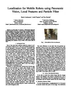
Figure 1 is a picture of the robot and the docking system. The robot is shaped like a broad disc and is 35 cm in diameter. Two wheels on either side enable movement. The docking mechanism is composed of a toggle switch and of two arms that clasp the robot during docking.
(-1)
(0)
(1)
(-2)
(2)
(-3)
(3)
(-4)
(4)
30° 40°
mobile robot
IR LEDs
docking station
docking station 1
2
3
4
5
Figure 2: The homing system and the regions divided by infrared beams
2.2 IR sensors IR LEDs
Figure 1: The robot and the docking system
2.1
Homing System
The homing system is composed of an infrared transmitter and an infrared receiver. The former is located at the center of the docking station and the latter is located at the front of the robot, as shown in Figure 2. The IR LED used by the transmitter has a transmission angle of ±20°. The transmission range of the LED beam is set to 2 m by adjusting the loading current. 5 LEDs are used in total and are arranged at intervals of 30°, resulting in the division into nine regions of a ±75 ° area at the front of the docking station.
Docking Mechanism
The docking mechanism shown in Figure 3 is designed to modify its posture to adapt to the robot when the robot approaches the docking station imperfectly and has an offset or an angle error. Also, the mechanism is designed to maintain a robust docking state against disturbances that may occur for various reasons during battery charges and tool exchanges. The proposed system has two great merits. First, the docking mechanism is operated by the driving force of the robot. When the robot docks, the impact releases a toggle switch. This two-latch switch is responsible for changing the configuration of the docking mechanism so that the robot can be clasped in the holding arms. The benefit of this system is that it does not require any sensors, driving units, or electronic devices to control the mechanism.
288
1st International Conference on Sensing Technology November 21-23, 2005 Palmerston North, New Zealand
Simultaneously, the toggle switch is contracted to be as short as the spring of the side pressure link, which doesn’t contract.
Gripper
Holding arm
Side-pressure link Toggle spring Base plate
(a)
(b)
(c)
(d)
Figure 3: Proposed docking mechanism
Second, the mechanism can automatically adjust itself to correct any offset errors or angle errors of the robot’s approach. The offset errors and angle errors that may occur can be compensated by the 1 DOF yaw motion and 1 DOF linear motion of the docking mechanism. The holding arms that are connected to the toggle switch raise the yaw motion, and the toggle switch has linear motion against a base plate. The yaw motion of each arm allows the docking mechanism to rotate to correct angle errors of an approaching robot. Torsion springs in the arms are used to bring an adjusting unit to the proper position for an offset error. The adjusting unit consists of holding arms, a toggle switch, a side pressure link, and a gripper. A prismatic joint between the toggle switch and the base plate compensates for offset errors made by the robot. A compression spring located in the prismatic joint brings the adjusting unit back to the initial position after undocking. After adjusting for offset errors and angle errors, the side-pressure links robustly maintain the docking state. The link consists of a serially connected spring and damper. When the docking mechanism is adapted to the robot, the toggle switch is on the going of contracting and the spring in the side-pressure link contracts to apply force to the gripper. As the robot reaches the docking station, the compression springs in the side-pressure link bring the grippers into contact with the robot. Then the toggle switch changes into its second state, which is the docking state. After the battery has been recharged, the robot pushes against the docking station again so that the state of the toggle switch changes back into the first state. Then the robot leaves the station to perform another task and the docking mechanism returns to its initial configuration. Figure 4 shows the docking procedure in detail. Figure 4 (a) shows the robot making contact with the holding arm. The torsion spring between the arm and toggle switch drives the adjusting unit to move in a direction that will correct an offset error.
Figure 4: Docking procedure
After that, the docking mechanism starts adjusting itself to the robot by reconfiguring the links and the springs, as shown in Figure 4 (b). When one of the holding arms is inserted into the robot’s groove while the gripper presses the groove, the robot automatically rotates to the required direction, thereby reducing an angle error. Next, the opposite gripper is vice versa. The two grippers strongly grasp the robot until docking is completed and the toggle switch changes to the second latch state, as shown in Figure 4 (c). A docking state cannot be released unless external force is applied to the toggle switch. After finishing the task in the station, the mobile robot pushes the toggle switch and then escapes from it backward in order to undock. Figure 4 (d) shows the undocked state. It is important that the grippers are opened by the torsion spring when the robot is released from them after pushing the toggle switch because this causes the toggle switch to return to the first state and allows the robot be released from the docking mechanism. After undocking is complete, the elasticity of the springs causes the docking mechanism to return to its initial configuration.
3 3.1
Homing system utilizing infrared sensors Idea
To implement homing movements, the relative angle between the robot and the docking station must be known. As shown in Figure 2, infrared beams emitted from the LEDs divide the semi-circle in front of the
289
1st International Conference on Sensing Technology November 21-23, 2005 Palmerston North, New Zealand
docking station into nine regions. Depending on where the robot is located among these nine regions, the robot repositions itself based on predetermined movement patterns. As shown in Figure 5, infrared signals from each LED are encoded like an infrared remote controller, so it is possible to know which LED is emitting the sensed signal. The coded signal is composed of a header and some pulses. The former is the beginning of a signal and the latter is information about which LED is emitting. In case interfering noise exists, the latter is repeated once. header
code1
When both the angle of the central region, and the distance from the robot to the docking station measured by a simple range sensor are smaller than the prescribed values, the homing movement is completed and the robot can then turn to the docking state. If the robot fails to dock, it will make subsequent attempts to achieve docking. To determine whether or not docking has been successful, a simple method, such as checking the recharging current, can be used. In Figure 6, a flowchart of the homing procedure is presented. Each state of the algorithm is programmed by using C language.
code2 (code1 repeated) homing starts
20ms 10ms 10ms(duty=0.5) 30ms
50ms
50ms
direction of the docking station
70ms
200ms turn
Figure 5: Code of IR LED signals located region No
For example, if only a signal from LED No. 4 is perceived, the robot must be in region No. 2, as shown in Figure 2. If signals from both LED No. 3 and No. 4 are perceived, then the robot must be in region No. 1.
central region?
back
turn
Yes forward
Therefore, using the LED signals enables the robot to estimate which region it is located in, and it can then move to the central region according to the predetermined movement pattern. After the robot is positioned in the central region, the robot moves through that region as a line-tracer moves in zigzags along a line until it finally reaches the docking station.
No
docking position? Yes angle < prescribe value ?
No
Yes docking starts
3.2
Algorithm
Figure 6: A flowchart of the homing procedure
When the robot reaches a predetermined location within range of the docking station and starts to home in on the docking station, the robot’s position is estimated using the aforementioned method. If the robot is not facing the docking station, it rotates until the center sensors perceive infrared signals from LEDs. The robot turns until its left- or right-hand side sensor faces the docking station. Then, it moves forward until the side sensor perceives the signal from the central LED and it moves to the central region. Once it reaches the central region, it turns to the front of the docking station and then, like a line-tracer, it zigzags along the central region to the docking station. If the robot goes out of the central region during this exercise, it will again rotate until it perceives signals from the central LED and can correct its directionality. By repeating this procedure, the robot can successfully reach the docking station.
4 4.1
Experiment Setup
The docking station was implemented and the experiments were carried out using the proposed system. In Figure 1, the implemented system is shown. The IR LED used is EL-8L and the applied current on each LED is 50 mA. It emits encoded infrared signals that have a 200 ms period and are modulated by 38 kHz. To generate encoded signals, LabViewTM from National Instruments Co. is used. The sensor for infrared detection is TSOP4838 from Vishay Co., which responds only to signals modulated by 38 kHz. To measure the distance from the robot to the docking station in a short range, GP2D120 from Sharp Co. is
290
1st International Conference on Sensing Technology November 21-23, 2005 Palmerston North, New Zealand
used. This distance-measuring sensor is primarily used to identify and locate obstacles. The board embedded for control of the robot and sensing is a DSP board that uses a TMS320F2812 chip from Texas Instruments Co. Software for the board is coded using Code Composer StudioTM. The interface between the DSP board and the computer for programming is JTAG XDS510 USB from Spectrum Digital Co. The robot samples infrared signals in a 2 ms period and determines the above-mentioned codes by analyzing the sampled data. Then, it estimates its position by a 100 ms period and chooses its movement patterns accordingly. To guarantee realtime processing, scheduling functions such as ‘mailbox’ and ‘task’ are used. These functions are supported by the DSP chip and Code Composer StudioTM.
4.2
Experimental results
Figure 7 shows the robot docking at the docking station. According to the experimental results, the range in which homing is possible is 0.5 ~ 2 m from the docking station, at an angle of ±75°. If the distance from the docking station to the robot is too far, the infrared beam cannot reach the sensors. On the other hand, if the distance is too short, the robot will collide with the docking station’s arms.
error of ±30°. The probability of successful docking on the first attempt is over 95%. If the robot fails to dock, successive attempts are usually successful. Unfortunately, there is a problem with infrared beam reflection on objects between the robot and the docking station, which could cause the robot to mistake its location within the nine regions. By modifying the control software of the robot so that it is appropriate to certain specific situations, the reflection problem can be solved so that docking is possible. However, it does not seem possible to find a general solution for this issue with this system.
5
Conclusion
This paper proposed an efficient docking system for household mobile robots. Despite the use of cheap infrared sensors, the proposed system was able to perform docking successfully. The homing system and the docking mechanism that constitute the docking system were explained, and the experimental results of using the system were presented. The robot was able to home in to the docking mechanism within a radius of 2 m around the docking station. The docking mechanism was able to compensate for offset errors of ±5 cm and angle errors of ±30°, and the probability of successful docking on the first attempt was over 95%.
6
Acknowledgements
This research was supported by LG Electronics Co. and Brain Korea 21.
7
References
[1]
Oh, S., Zelinsky, A., and Taylor, K., “Autonomous battery recharging for indoor mobile robots” Silverman, M.C., Nies, D., Jung, B., and Sukhatme, G.S., “Staying alive: a docking station for autonomous robot recharging,” IEEE International conference on robotics and automation, pp. 1050-1055 (2002) Hada, Y., Yuta, S., “Robust navigation and battery re-charging system for long term activity of autonomous mobile robot,” International conference on advance robotics,” pp.297-302 (1999) Hada, Y., Yuta, S., “A first experiment of long term activity of autonomous mobile robot – result of repetitive base-docking over a week,” International symposium on experimental robotics, pp. 235-244 (2000) Colens, A., Mobile robots and their control system, U.S. Patent No. 6,389,329 (2002)
[2]
[3]
Figure 7: The robot and the docking station under docking state
During experiments, some unexpected situations occurred, so we modified our software to cope with each instance. For example, it sometimes happens that the robot misses the infrared signal and then fails to find the dock. In this case, after a prescribed time elapses, the robot initiates the homing procedure over again.
[4]
[5]
The error range of the robot’s entrance that can be compensated by the docking mechanism is a maximum offset error of ±5 cm and a maximum angle
291