INTERNATIONAL JOURNAL OF PRECISION ENGINEERING AND MANUFACTURING Vol. 15, No. 6, pp. 1015-1022
JUNE 2014 / 1015
DOI: 10.1007/s12541-014-0430-x
Development of Hybrid Clinched Structure by using Multi-Cohesive Zone Models Chan-Joo Lee1, Jung-Min Lee1, Kyung-Hun Lee2, Dong-Hwan Kim3, Ho-Yeun Ryu1,
and
Byung-Min Kim4,#
1 Dongnam Regional Division, Korea Institute of Industrial Technology, 189, Dongjin-ro, Jinju-si, Gyeongsangnam-do, South Korea, 660-805 2 PNU-IFAM Joint Research Center, Pusan National University, 2, Busandaehak-ro 63beon-gil, Geumjeong-gu, Busan, South Korea, 609-735 3 Department of Mechanical & Automotive Engineering, International University of Korea, 965, Dongbu-ro, Munsaneup, Jinju-si, Gyeongsangnam-do, South Korea, 660-759 4 School of Mechanical Engineering, Pusan National University, 2, Busandaehak-ro 63beon-gil, Geumjeong-gu, Busan, South Korea, 609-735 # Corresponding Author / E-mail:
[email protected], TEL: +82-51-510-3074, FAX: +82-51-581-3075 KEYWORDS: Hybrid joining, Clinching, Multi cohesive zone models, Crashworthiness
Recent design concept of automotive body, as called multi-material design, is required a new joining method to join no-ferrous metal like aluminum alloy. One of new joining methods is hybrid joining combined with mechanical joining and adhesive bonding. The purpose of this study is to propose the multi- cohesive zone models (CZMs) for design of the hybrid joined structure with AA6063 alloy sheets. To evaluate the crashworthiness of hybrid clinched structure, the failure behavior of hybrid clinching was described by multi-CZMs. Cohesive parameters of mechanical joined and adhesive bonded parts in hybrid joining were determined by numericalexperiment approximation technique. The crashworthiness of top-hat specimen joined by hybrid clinching was designed based on the crash analysis with multi-CZMs. Also, the crash test was performed to verify the effectiveness of multi-CZMs. In crash analysis and experiment, the hybrid clinched specimen absorbed 1778 J and 1814 J of impact energy at half of total penetration depth than mechanical clinched specimen, respectively. Manuscript received: April 15, 2013 / Revised: March 20, 2014 / Accepted: May 7, 2014
NOMENCLATURE ti = Traction stress for normal and shear mode ti0 = Damage initiation traction stress D = Scalar damage variable GiC = Critical fracture strain energy η = Mode mixity
1. Introduction Recently, multi-material design concept of automotive body, used aluminum and magnesium alloy for light-weight, is required a new joining method to replace the conventional resistance spot welding.1-3 Mechanical joining methods, such as self piercing rivet (SPR) and clinching, are the most popular joining methods for non-ferrous materials like aluminum alloy in automotive industry. However, their joint strengths are 50~70% weaker than spot welding.
© KSPE and Springer 2014
In automotive industry, the hybrid joining method, combined with mechanical joining and adhesive bonding, is a good solution to improve the joint strength of mechanical joints. Also, it is well known that modern structural adhesive provides a better crash performance in automotive body. In the design f automotive body, the crashworthiness is one of important factors, and nowadays is commonly analyzed by FEanalysis.4,5 According to industrial observations, the behavior of spotwelding is defined as rigid in joined region of automotive body. Xiang et al.6 have been optimized crashworthiness of spot-welded thin-walled hat section using various joint models. Rigid-node spot-weld model has been suitable for crash analysis when no spot-weld failure occurred. But the hybrid joined structure generally includes the failure of mechanical joining during the crash test because mechanical joining is fastened by physically not chemically like spot-welds. Porcaro et al.7 predicted the joint strength of SPR using FE-analysis included the shape of mechanical joint. But it is impossible that the shape of mechanical joint applied to shell based thin-walled structure. Therefore, the shell based FE-model for hybrid joined structure required the failure model of hybrid joint to evaluate the role of hybrid joint in
1016 / JUNE 2014
INTERNATIONAL JOURNAL OF PRECISION ENGINEERING AND MANUFACTURING Vol. 15, No. 6
automotive part. The purpose of this study is to propose the multi-cohesive zone models(CZMs) for design of the crashworthiness of hybrid joined structure. The multi-cohesive zone model consisted with two region referred the mechanical joining and adhesive bonding, respectively. The failure behavior of each region depends on their cohesive parameters. The cohesive parameters of mechanical joint and adhesive bonding were evaluated by numerical-experimental approximation technique. In this study, the adhesive bonding and clinching was used for hybrid joining. The clinching process is one of mechanical joining methods to join the dissimilar materials by geometrical interlocking formed by punch and die. According to Varis,8 the clinching process is cheaper than any other mechanical joining method because additional joining element is no required. Lee et al. was proposed the design method of mechanical clinching process and optimized the joint strength of mechanical clinching with aluminum alloy. In this study, the mechanical clinching tools designed by Lee et al.9 were used for hybrid joining. The crashworthiness of the top-hat specimen joined by hybrid clinching was evaluated by crash analysis with multi-CZMs. Effects of the number of hybrid clinched joints on the peak load, penetration depth and absorbed energy were investigated. Based on the result of crash analysis the number of hybrid clinched joints was optimized to have similar crashworthiness compared with specimen joined with SPR. To verify the effectiveness of proposed multi-CZMs, the crashworthiness of hybrid clinched structure evaluated by crash analysis was compared with the result of crash test.
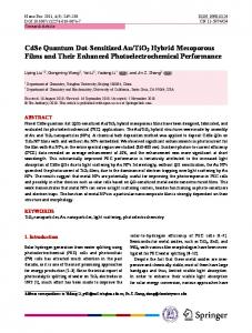
2. FE-Model for Shell Based Hybrid Clinched Structure 2.1 FE-model with multi-CZMs To evaluate the role of joint in automotive body, the shell-based joint models with failure criteria of joint are required in large-scale crash analysis. As shown in Fig. 1, the hybrid clinched joint was simplified by using cohesive elements. The section 1 and 2 referred the mechanical clinched joint and adhesive bonded area, respectively. In this study, the CZM supported in the commercial FE code ABAQUS was employed to analyze the fracture process of hybrid clinched joint. CZM is a two parameter failure criterion that describes the fracture process of an interface of joint.10,11 The traction-separation law of CZM is illustrated in Fig. 2. The damage initiation criterion is given by: ⎛ 〈 t n〉 ⎞ 2 ⎛ t s ⎞ 2 ⎛ t t ⎞ 2 -⎟ + ⎜ ---⎟ + ⎜ ---⎟ = 1 ⎜ ------⎝ t0n ⎠ ⎝ t0s ⎠ ⎝ t0t ⎠
(1)
Here, < > is Macaulay brackets, emphasizing that a pure 0 0 compression mode does not consider the damage initiation. tn , ts , and 0 tt are the peak value of traction stress for pure normal and shear mode deformation, respectively. The damage initiates when a quadratic 0 interaction function reaches a value of one. For tn < 0, the shear traction is only considered in damage initiation criterion. Once the damage initiation criterion is satisfied, the damage evolution law dominated the damage behavior of cohesive element until its failure. In this study, a scalar damage variable, D, is adopted to describe the damage behavior of cohesive element. The damage
Fig. 1 Simplification of hybrid clinched joint by using cohesive element
Fig. 2 Mixed-mode traction-separation law in CZM
evolution law is modeled by D as followings: ⎧ ( 1 – D )tn tn = ⎨ ⎩ t
tn > 0 tn ≤ 0
(2)
ts = ( 1 – D )ts , tt = ( 1 – D )tt Here, tn , ts and tt are the stress components predicted by the initial traction-separation behavior for current strains without damage. To consider the crack closing effect by compressive load, the compressive stress has no damage for tn < 0 . D develops from 0 to 1 by external loading after the damage initiation. Once the overall damage variable reaches D=1, the tractions in normal and shear modes are zero. Thus, the adhesives offer no resistance against the deformation of adhesively bonded structure. The dependence of the fracture energy on the mode mix used in this study is BK form12 as following: η
C C C C ⎧G ⎫ G = Gn + ( GS – Gn ) ⎨ -----S- ⎬ ⎩ GT ⎭
(3)
Here, GS = Gs + Gt, GS = Gn + Gs, and η = 1 are a material parameter related with mode mixity. Gn, Gt and Gs are work done of cohesive C C element. Gn , GS and GC are critical fracture energy in pure normal, pure shear and mixed mode fracture.
2.2 Cohesive parameters of hybrid clinched joints Cohesive parameters of mechanical clinching and adhesive bonded area were determined the values which provides the best numericalexperimental approximation to the load-displacement curves by comparison of the results of the FE-analysis and experiment. Hwang et al.13 and van den Bosch et al.14 proposed the evaluation method of cohesive parameters from the experimental data and showed that the
INTERNATIONAL JOURNAL OF PRECISION ENGINEERING AND MANUFACTURING Vol. 15, No. 6
JUNE 2014 / 1017
Table 1 Mechanical properties of AA6063 alloy sheet Elastic modulus 70.1 GPa
Yield stress 132.08 MPa
Flow stress σ = 502.46ε 0.177
cohesive parameters obtained by their method well-described the failure behavior of mechanical clinched joint. Based on numericalexperimental approximation technique, the normal and shear mode cohesive parameters were extracted from tensile mode and shear mode tests. Tensile mode cohesive parameters of mechanical clinched region and adhesively bonded area were evaluated by H-type tensile test and T-peel test. And the single lap shear tests were performed to evaluate shear mode cohesive parameters of mechanical clinched region and adhesively bonded area. In single lap shear test, the normal stress was occurred at the end of overlap due to the bending of adherends. To evaluate the cohesive parameters for shear mode, the tensile mode cohesive parameters were required preferentially. Numerical studies of single lap shear test were performed with tensile mode cohesive parameters to consider their contributions to fracture of single lap shear test was considered test. From the numerical studies including tensile mode cohesive parameters, the shear mode cohesive parameters neglecting the normal stresses generated in single lap shear test were determined as the case which described the failure behavior of single lap shear specimen. In numerical studies, the hybrid clinched area was modeled by using cohesive elements. Thickness of cohesive element was determined as 0.1 mm of adhesive layer thickness. The failure of cohesive element depended on the relative displacement of deformed adherends. To reduce the numerical instability, cohesive element size was modeled less than 0.2 mm. The adherends are modeled by solid element with elastic-plastic material model. AA6063 alloy sheet with 2.4 mm of thickness was used for adherends. The mechanical properties of Al6063 alloy sheets listed in Table 1 were evaluated by tensile test. Cohesive element and solid element were connected by node share technique. Newton-Raphson method was used for solving the constitutive equation of hybrid clinched structure with multi-CZM. To identify the cohesive parameters of mechanical clinched region, the H-type tensile and single lap shear test was performed for tensile mode and shear mode test, respectively. Punch with 7.0 mm diameter and die with 9.6 mm diameter designed by Lee et al.9 were used to fabricate the mechanical clinched specimens. The dimensions of specimens were illustrated in Fig. 3. For tensile mode, the damage initiation stresses and critical fracture energy of mechanical clinched region were 25.59 MPa and 47.21 kJ/mm2. For shear mode, the damage initiation stresses and critical fracture energy of mechanical clinched region were 35.40 MPa and 54.85 kJ/mm2. The cohesive parameters of adhesive bonded area were evaluated by T-peel and single lap shear test. The dimensions of specimens were shown in Fig. 4. The adhesive used in this study was Terokal 4555B made by Henkel technologies. The adhesive was cured at 180oC for 20 minutes. Specimens are pulled in one direction with 254 mm/min load velocity. For tensile mode, the damage initiation stresses and critical fracture energy of adhesive bonded area were 37.23 MPa and 1.006 kJ/ mm2. For shear mode, the damage initiation stresses and critical fracture energy of adhesive bonded area were 28.11 MPa and 3.198 kJ/ mm2.
Fig. 3 Identification of cohesive parameters of mechanical clinched region by tensile and shear mode test
Fig. 4 Identification of cohesive parameters of adhesive bonded area by tensile and shear mode test
1018 / JUNE 2014
INTERNATIONAL JOURNAL OF PRECISION ENGINEERING AND MANUFACTURING Vol. 15, No. 6
Fig. 6 FE-model for crash analysis of hybrid clinched structure
Fig. 5 Comparison of load displacement curves of hybrid clinched Tpeel specimen in FE-analysis and experiment
2.3 Verification of multi-CZM Hybrid clinched T-peel specimen was fabricated and T-peel test was performed to verify the effectiveness of proposed FE-mode with multiCZMs. Generally, an adhesive bonded joint showed inherently high strength in shear mode loading condition but has remarkable lower peel strength when peel load applied. T-peel test is a suitablemethod to evaluate the effect of hybrid joining on the joint strength because of its long failure displacement. Fig. 5(a) shows the dimensions of T-peel specimen joined by hybrid clinching. Total length of hybrid clinched region was 70 mm and a distance between peel arm and first mechanical clinched joint is 20 mm. A pitch between two mechanical clinched joints and is 30 mm. Fig. 5(b) shows the load-displacement curves obtained FE-analysis and experiment. Load increased to the point where to start peel as the result of T-peel test joined with adhesive and drop rapidly. And then joining load increase again to the point where first joint is fractured and drop after fracture over again. Load-displacement in FE-analysis showed a good agreement with experiment data. Maximum load of the joint amounts to about 1.8 kN. First clinched joint was fractured at around 4.5 mm of displacement and at around 12 mm of displacement, the Tpeel specimen was failed completely in FE-analysis and experiment. It notes that FE-analysis with multi CZMs could well describe the failure behavior of hybrid clinched joint.
Fig. 7 Configuration of top-hat specimen
3. Design of Hybrid Clinched Structure Using MultiCZMs 3.1 FE-model for crash analysis of hybrid clinched structure Crashworthiness of hybrid jointed structure with multi point was evaluated by crash analysis of top-hat specimen. Fig. 6 shows the FEmodel of multi hybrid clinched top-hat specimen under impact loading condition. Fig. 7 shows the dimensions of top-hat specimen. The tophat specimen consisted with hat specimen and flat reinforcement. The flange of hat specimen was joined with flat reinforcement by hybrid clinching. In FE-model, it was connected by two cohesive elements for adhesive bonded area and mechanical clinched joint, respectively. The end of top-hat specimen was fixed on the rigid wall. 3,000 J of impact energy was applied by impactor with 200 kg of mass and 5.48 m/s of initial velocity. The hybrid clinched joint located evenly along the flange length, L (=333 mm), with equal pitch, P. The pitch corresponding the number of hybrid clinched joint, n, is determined as following Eq. (4):
INTERNATIONAL JOURNAL OF PRECISION ENGINEERING AND MANUFACTURING Vol. 15, No. 6
JUNE 2014 / 1019
Fig. 8 Result of high speed tensile test of AA6063 alloy sheet
P = ( L – 2P0 – dC ⋅ n ) ⁄ n
(4)
Here, P0 (=20 mm) is the distance of clinched joint and end of specimen. dC is the diameter of clinched joint. AA6063 alloy sheet with 2.4 mm of thickness was used for material of specimen. The high speed tensile test was performed to evaluate the effect of strain rate on flow stress in dynamic loading condition. The result of high speed tensile test as shown in Fig. 8 was used for the flow stress of AA6063 alloy sheet. Rate dependent flow stress indicated that the cohesive properties of mechanical clinching are increased in high speed loading condition because mechanical clinching was separated with deformation and failure of materials of joined area. According to previous studies,15,16 the cohesive parameters of adhesive bonding have been influenced by strain rate. Especially, crashworthiness of adhesively bonded structure are improved because cohesive parameters have been increased in high speed loading condition. Thus, further studies to evaluate rate dependent cohesive parameters of hybrid clinching are required to describe collapse behavior of hybrid clinched structure more accurately in FE-analysis.
3.2 Crashworthiness of hybrid clinched structure Crash analysis was executed by commercial s/w ABAQUS 6.8. Impact load curves in crash analysis are represented in Fig. 9(a). The maximum load of top-hat specimen is similar and distributed in range of 163.9±1.35 kN. The number of hybrid clinched joint was not influenced to maximum load of top-hat specimen because the maximum load is mainly depended on the section properties of structure when the joint has enough strength to endure the external load. Thus, it notes that the hybrid clinching joint can provide the sufficient strength to act as structural joint. After collapse of top-hat specimen start, the load plateaus until end of collapse. At end of load-displacement curve, the load is slightly increased again because the stiffness of crashed specimen is increased by plastic deformation of substrate. The impact energy was consumed to disrupt the hybrid clinched joint. The fracture energy at flange of top-hat specimen is increased with increasing of the number of hybrid clinched joint. It results that the penetration depth was decreased plateau load was slightly increased with increasing of the number of hybrid clinched joint. To evaluate the crashworthiness of top-hat specimen, the absorbed energy was evaluated
Fig. 9 Result of high speed tensile test of AA6063 alloy sheet
Fig. 10 Drop tower test machine
during crash analysis, as shown in Fig. 9(b). The initial absorbed energy of each specimen was similar because the initial absorbed energy was dominantly depended on the maximum load and the fracture energy of hybrid clinched joint was relatively small amount. The effect of number of hybrid clinched joint on absorbed energy was observed over 30 mm of penetration depth with the plateau impact load.
3.3 Design of hybrid clinched structure Based on the result of crash analysis, the number of hybrid clinched
1020 / JUNE 2014
INTERNATIONAL JOURNAL OF PRECISION ENGINEERING AND MANUFACTURING Vol. 15, No. 6
joint was determined to design the top-hat specimen with equivalent crashworthiness of SPR specimen with 8 points of joints. The crashworthiness of SPR specimen under 3000 J of impact energy was evaluated by drop tower test, as shown Fig. 9(a). Fig. 9(b) shows the load-penetration curve of SPR specimen. The maximum load and penetration depth were 161.22 kN and 58.96 mm, respectively. And average plateau load was 39.2 kN. The absorbed energy at 29.74 mm which is 50% of total penetration depth was evaluated to exclude the end effect of crashed specimen and was 1789 J. The penetration depth of SPR specimen was similar value of 11 points hybrid clinched specimen. And the 8 points hybrid clinched specimen has similar the absorbed energy at 30.04 mm, as 1778 J, compared with SPR specimen. The crash resistant structure in automotive body should be guaranteed the safety against the impact load. Thus, the number of hybrid clinched joint was determined 11 points which could absorb impact energy more than 9 points.
Fig. 11 Comparison of load-displacement curves of hybrid clinched and SPR top-hat specimens
4. Impact Test of Hybrid Clinched Structure Crashworthiness of top-hat specimen with 11 points of hybrid clinched joint was evaluated by the drop tower test, as shown in Fig 11. Fig. 12 shows comparison of load-displacement curves of 11 point hybrid clinched top-hat specimen with SPR. From the drop tower test, 11 points hybrid clinched specimen has 161.38 kN maximum load and 56.78 mm penetration depth. At 28.39 mm of penetration depth, the absorbed energy was 1814 J. The absorbed energy of hybrid clinching in experiment was higher than FE-analysis. It indicated that the rate dependent cohesive parameters of mechanical clinching and adhesive bonding not considered in this study. Especially, in high speed condition, the visco-elastic deformation of adhesive can blunt moving cracks and the energy is more required for crack propagation.17,18 The collapse shape of hybrid clinched top-hat specimen in experiment was compared with crash analysis with shell based FEmodel with multi extended CZMs, as shown in Fig. 13. Both top-hat specimens in experiment and crash analysis showed regular progressive collapse. In crash analysis, 4 points of hybrid clinched joint was failed and the hybrid clinched joint near crashed part was partially damaged. In the experiment, 4 points of hybrid clinched joint was damaged. It notes that FE-analysis with multi CZMs could be well-described the failure behavior of hybrid clinched joint. The hybrid clinched specimen was separated with cohesive failure of adhesive and button separation mode failure of mechanical clinched joint, as shown in Fig. 13. It indicated that the top-hat specimen absorbed the impact energy with the failure of the hybrid joined area. And it is a good reason for using the multi-CZMs in crash analysis of hybrid clinched structure. However, failure of aluminum was observed in crashed part of specimen. It notes that the failure behavior of aluminum is required to increase accuracy of crash analysis.
Fig. 12 Collapse shapes of hybrid clinched specimen in crash analysis and experiment
5. Conclusions In this study, FE-model with multi CZMs was proposed to evaluate the crashworthiness of hybrid clinched structures. Cohesive parameters
Fig. 13 Failure mode of hybrid clinched joint
INTERNATIONAL JOURNAL OF PRECISION ENGINEERING AND MANUFACTURING Vol. 15, No. 6
of adhesive and clinched joint were evaluated by a numericalexperimental approximation technique. The crash-worthiness of hybrid clinched structure was evaluated the drop tower test with top-hat specimen. From the result of FE-analysis and experiment, following conclusion can be drawn: (1) The mechanical clinched joints were simplified to connect substrate with cohesive elements in FE-model. From the comparison of FE-analysis and experiment of T-peel test, it was confirmed that the simplified FE-model of hybrid clinched joint well-described the failure behavior of multi point hybrid clinched joints. (2) The maximum load, penetration depth and absorbed energy of top-hat specimen joined by hybrid clinching were evaluated by crash analysis. The number of hybrid clinched joint was not influenced significantly to maximum load. The penetration depth and absorbed energy were increased with increasing of the number of hybrid clinched joint. Based on the result of crash analysis, the number of hybrid clinched joint was 11 points which had equivalent crashworthiness of SPR specimen with 8 points. (3) From the result of drop tower test, absorbed energy in experiment was about 3.8 % higher than crash analysis because of effect of visco-elastic deformation of adhesive not considered in this study. However, the hybrid clinched specimen showed similar loadpenetration depth curve with SRP specimen. Collapse shape of specimen in experiment has a good agreement with crash analysis. Also, the number of un-failed hybrid clinched joints was exactly predicted by crash analysis. Thus, the FE-model with multi CZMs can be well-described the failure behavior of hybrid clinched joint under impact loading condition.
ACKNOWLEDGEMENT This work was supported by the National Research Foundation of Korea (NRF) Grant funded by the Korea government (MSIP) (No. 2012R1A5A1048294) and PNU-IFAM Joint Research Center.
REFERENCES
JUNE 2014 / 1021
Strength Analysis,” Int. J. Precis. Eng. Manuf., Vol. 12, No. 6, pp. 1031-1034, 2011. 5. Park, D. K. and Jang, C. D., “Optimum SUV Bumper System Design Considering Pedestrian Performance,” International Journal of Automotive Technology, Vol. 11, No. 6, pp. 819-824, 2010. 6. Xiang, Y., Wang, Q., Fan, Z., and Fang, H., “Optimal Crashworthiness Design of a Spot-Welded Thin-Walled Hat Section,” Finite Elements in Analysis and Design, Vol. 42, No. 10, pp. 846-855, 2006. 7. Porcaro, R., Langseth, M., Weyer, S., and Hooputra, H., “An Experimental and Numerical Investigation on Self-Piercing Riveting,” International Journal of Material Forming, Vol. 1, No. 1, pp. 1307-1310, 2008. 8. Varis, J., “Economics of Clinched Joint Compared to Riveted Joint and Example of Applying Calculations to a Volume Product,” Journal of Materials Processing Technology, Vol. 172, No. 1, pp. 130-138, 2006. 9. Lee, C. J., Kim, J. Y., Lee, S. K., Ko, D. C., and Kim, B. M., “Design of Mechanical Clinching Tools for Joining of Aluminium Alloy Sheets,” Materials & Design, Vol. 31, No. 4, pp. 1854-1861, 2010. 10. Blackman, B., Hadavinia, H., Kinloch, A., and Williams, J., “The Use of a Cohesive Zone Model to Study the Fracture of Fibre Composites and Adhesively-Bonded Joints,” International Journal of Fracture, Vol. 119, No. 1, pp. 25-46, 2003. 11. Kim, S. C., Kim, J. S., and Yoon, H. J., “Experimental and Numerical Investigations of Mode I Delamination Behaviors of Woven Fabric Composites with Carbon, Kevlar and their Hybrid Fibers,” Int. J. Precis. Eng. Manuf., Vol. 12, No. 2, pp. 321-329, 2011. 12. Benzeggagh, M. L. and Kenane, M., “Measurement of Mixed-Mode Delamination Fracture Toughness of Unidirectional Glass/Epoxy Composites with Mixed-Mode Bending Apparatus,” Composites Science and Technology, Vol. 56, No. 4, pp. 439-449, 1996.
1. Lee, C. J., Kim, J. Y., Lee, S. K., Ko, D. C., and Kim, B. M., “Parametric Study on Mechanical Clinching Process for Joining Aluminum Alloy and High-Strength Steel Sheets,” Journal of Mechanical Science and Technology, Vol. 24, No. 1, pp. 123-126, 2010.
13. Hwang, B. N., Lee, C. J., Lee, S. B. and Kim, B. M., “Analysis and Application of Mechanical Clinched Joint Using Cohesive Zone Model,” Trans. Mater. Process, Vol. 19, No. 4, pp. 217-223, 2010.
2. Abe, Y., Matsuda, A., Kato, T., and Mori, K. I., “Plastic Joining of Aluminium Alloy and High Strength Steel Sheets by Mechanical Clinching,” Steel Research International, Vol. 79, No. 1, pp. 649656, 2008.
Sheet,” Journal of Materials Processing Technology, Vol. 209, No. 1, pp. 297-302, 2009.
3. Kim, W. K., Won, S. T., and Goo, B. C., “A study on Mechanical Characteristics of the Friction Stir Welded A6005-T5 Extrusion,” Int. J. Precis. Eng. Manuf., Vol. 11, No. 6, pp. 931-936, 2010. 4. Heo, U., Kim, S. K., Song, M. J., Yang, I. Y., and Im, K. H., “Effectiveness Evaluation for Seat Parts by Seat Belt Anchorage
14. Van den Bosch, M., Schreurs, P., and Geers, M., “On the Prediction of Delamination during Deep-Drawing of Polymer Coated Metal
15. Blackman, B. R. K., Kinloch, A. J., Rodriguez Sanchez, F. S. R., Teo, W. S., and Williams, J. G., “The Fracture Behaviour of Structural Adhesives under High Rates of Testing,” Engineering Fracture Mechanics, Vol. 76, No. 18, pp. 2868-2889, 2009. 16. Iwamoto, T., Nagai, T., and Sawa, T., “Experimental and Computational Investigations on Strain Rate Sensitivity and Deformation Behavior of Bulk Materials made of Epoxy Resin
1022 / JUNE 2014
INTERNATIONAL JOURNAL OF PRECISION ENGINEERING AND MANUFACTURING Vol. 15, No. 6
Structural Adhesive,” International Journal of Solids and Structures, Vol. 47, No. 2, pp. 175-185, 2010. 17. Rahulkumar, P., Jagota, A., Bennison, S., and Saigal, S., “Cohesive Element Modeling of Viscoelastic Fracture: Application to Peel Testing of Polymers,” International Journal of Solids and Structures, Vol. 37, No. 13, pp. 1873-1897, 2000. 18. Wang, J., Kang, Y. L., Qin, Q. H., Fu, D. H., and Li, X. Q., “Identification of Time-Dependent Interfacial Mechanical Properties of Adhesive by Hybrid/Inverse Method,” Computational Materials Science, Vol. 43, No. 4, pp. 1160-1164, 2008.