22nd International Symposium on Automation and Robotics in Construction ISARC 2005 - September 11-14, 2005, Ferrara (Italy)
1
Development of MEMS-Based Vibration Sensor for Tunnel Construction and Maintenance Monitoring System Jung-Yeol Kim , Soon-Wook Kwon, Hyun-Seok Yoo, Moon-Young Cho
Abstract—Recently, the demand for sensor technology has increased remarkably in all industrial fields. Sensor technology is closely related to cutting-edge technologies such as semiconductor technology and minute structure building technology, and thus, the high demand for small and light devices with high performance provides the impetus for conducting studies in order to develop sensors with much better performance. In this study, we developed a MEMS-based vibration sensor for tunnel construction and maintenance monitoring system. For this, we investigated the definition and summary of MEMS technology and also analyzed the types and characteristics of MEMS processing technology and the strong points of MEMS technology. We also analyzed current research results on sensor applications based on MEMS for construction. The types of work, characteristic and frequency of tunnel measurement, and investigated the characteristics of measuring instruments for doing the pertinent works are analyzed. We manufactured the MEMS vibration sensor for tunnel construction in order to measure blast vibration and we also measured the vibration through experiments. Index Terms—MEMS, Accelerator, Sensor, Measurement, Tunnel Monitoring, Automation
I. INTRODUCTION A. Background and purpose of study uring the process of tunnel construction, there is a need to measure various spots during excavation in order to verify the feasibility and constructability of the construction based on the initial design. Also, with the recent increase in environmental interest, the frequency of measuring vibration and noise accruing during the excavation job has also increased. Recent sensor technology is closely related to cutting-edge technologies such as semiconductor technology and minute
D
This work is supported by the Ministry of Planning and Budget in Korea (ROK). Jung-Yeol Kim is with the Korea Institute of Construction Technology, Goyang, Korea (ROK) (e-mail:
[email protected]). Soon-Wook Kwon is with the Korea Institute of Construction Technology, Goyang, Korea (ROK) (corresponding author, phone: 82-31-9100-089; fax: 82-31-9100-544; e-mail: swkwon@ kict.re.kr). Hyun-Seok Yoo is with the Korea Institute of Construction Technology, Goyang, Korea (ROK) (e-mail:
[email protected]). Moon-Young Cho is with the Korea Institute of Construction Technology, Goyang, Korea (ROK) (e-mail:
[email protected]).
structure technology. Hence, many studies have been conducted in order to improve the performance of the various conventionally used sensors. The MEMS (Micro-Electro-Mechanical System) field, which has rapidly emerged with the advancements in semiconductor technology centering in the US, is a field of study for the production of micro-devices such as ultra-small structures, sensors, actuators and systems in which the MEMS technology is applied, and this has led to a new revolution in the world sensor market. The MEMS-based sensor market is expected to reach 10 billion dollars by 2006[1]. Recently, universities in the US, including Stanford Univ. and Carnegie Mellon Univ., have vigorously conducted researches on MEMS-based sensors for structural health monitoring[2]-[5]. As mentioned before, the sensors that utilize MEMS technology consume very little power, so that it can reduce the costs for data transmission and power supply. If a MEMS-based wireless measuring system is developed, it is expected that installation time and installation expenses will be cut by 75% and 50%, respectively, and it is also expected that it will have a remarkable spillover effect in case that the reduced expenses for sensors and maintenance are taken into consideration. Therefore, we manufactured a MEMS-based prototype in order to develop a measuring instrument for tunnels with high performance at a low cost. B. Scope and Method of Study There are a lot of measuring instruments for tunnels, but we confined the scope of the study to the development of a vibration sensor for construction (Low frequency, High durability). It is expected that the cases of sensor development presented in this study will contribute to develop other measuring instruments in the future. The methods of study are as follows: (1) Analyzed current research results of MEMS technology in the construction industry (2) Analyzed the types, characteristics of frequency of measurement, investigated the characteristics of measuring instruments used in measurement work, and analyzed the applicability of MEMS technology (3) Designed and developed a MEMS-based vibration sensor for tunnel construction to measure blast vibration, and we measured the vibration from tests
ISARC 2005
2
II. RESEARCH RESULTS OF MEMS BASED SENSING TECHNOLOGY IN THE CONSTRUCTION INDUSTRY
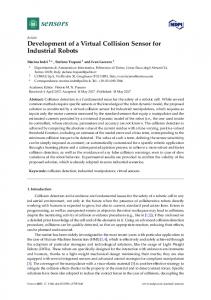
A. BiAST sensor for measuring the strain rate of tracks BiAST (Biaxial Strain Transducer) is a MEMS-based two-way strain sensor that was developed by the Seamans Center of the University of Iowa [5]. The sensor was developed for the purpose of estimating the fatigue life of rail structures by attaching the MEMS-based strain gauge on a track. An improved model from the UAST (Uniaxial Strain Transducer) prototype, which was developed as a one-way strain sensor, the BiAST sensor can be used for track structures that load weight in various ways or that change continuously. BiAST was also developed in order to improve the conventional metal foil-type strain gauge. The metal foil-type strain gauge has benefits such as cheaper price and ease of installment, but it also has barriers such as weak durability in outdoor environments, unstable linearity of signal, and measured values that change in the time lapse, so it is mainly used to measure dynamic strain for a short time. Therefore, it is expected that the MEMS-based strain sensor will solve the problems of conventional foil-type strain gauges[4]. B. Wireless piezoelectric vibration sensor for structure monitoring The piezoelectric vibration sensor was developed at Stanford University to provide decent performance at a high frequency for structures. To verify the initial vibration of a structure, it adopted the latest structural monitoring technique that measures the vibration of the structure at a high frequency.
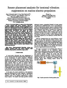
Fig. 1 Design of piezoelectric vibration sensor
As shown in Fig. 1, the pie-shaped piezoelectric vibration sensor is manufactured as follows. The proof mass is attached to a sensor housing using a cantilever, and then the wall of the cantilever is filled with piezoelectric material. If the sensor side is accelerated, then the proof mass is bent first and the piezoelectric material is strained almost simultaneously, which results in the electric resistance, which is the operational principle of the sensor [6]. It is configured a complete wireless sensing unit using a MEMS-based piezoelectric accelerator, a short-range wireless RF modem and a low-power micro-controller. The MEMS piezoelectric accelerator was attached on the interface board and the low-power micro-controller controlled both the sensor and the wireless modem. The wireless RF modem worked at 2.4Hz and it was designed to send and receive data within 350m.
① Wireless sensing unit
② Vibration experiment on a structure
Fig. 2 Vibration experiment on a structure and wireless sensing unit
The piezoelectric accelerator performance was measured by giving an artificial vibration to the -like model structure shown in Fig. 2 [6]. From the experimental result, we can verify that the piezoelectric vibration sensor has more excellent noise characteristics and better resolution compared to a capacitance vibration sensor with the same spec, and it is analyzed that there is a 0.3% error between the model and the theoretically analytic model.
②
III. ANALYSIS OF TUNNEL MEASUREMENT A. Overview of tunnel measurement Tunnel construction cannot always be conducted as planned because the investigated movement differs from the real movement due to the geological characteristics of the in-situ ground, even though enough investigation was done in the planning stage. For this reason, in the case of NATM (New Austrian Tunneling Method), which is mainly used in tunnel construction, it is possible to measure the vibration of various spots even during the excavation so that people can check the feasibility and constructability of the original design from time to time, and if necessary, the design can also be changed. When taking measurements, the purpose, usage, size, in-situ ground condition, surroundings and construction methods should be taken into consideration based on the preliminary investigation and analytical results worked on before the construction started in order to cope with the original design and construction. During the construction stage, the design should be changed if necessary, and then applied on the basis of the spot condition, ground condition and the initial measurement results. Tunnel measurement can be categorized into two kinds of measurements: measurement for construction and measurement for maintenance. The measurement for construction is divided into the representative points measurement and daily management measurement worked during all the phases of tunnel construction from the blasting and construction. B. Analysis of tunnel measurement Tunnel measurement for construction can be divided into daily management measurement and representative point
ISARC 2005 measurement. The daily management measurement is subject to all the construction area, which is to confirm the safety of the tunnel construction. The representative point measurement is subject to a representative ground or the first excavation area, which is to confirm the distribution of plasticity areas and movement such as support stress in order to verify the safety and design feasibility of support and to prepare the construction for future excavations. Table 1 shows a series of daily management measurements and representative point measurements [7].
3
beams. The sensing electrode is arranged in the right and left of the proof mass. It is designed to be a reverse between the movement direction of the proof mass and the change direction of the capacitance, which is called as the differential capacitance sensing method. This method improves linearity compared with single capacitance sensing.
TABLE I TUNNEL MEASUREMENT ITEM Group
Item
Face Mapping Daily management measurement
Represe ntative point measurement
Lining displacement measurement Tunnel Arch Subsidence Measurement Rock-bolt Pull-Out Test Soil Subsidence Measurement Underground Strain Measurement Rock-bolt Axial Force Measurement
Description -Sheets, joints & fractures of face & exposed surface -Ground water lakage conditions & volume -Strain and defects of supports -Lining strain convergence
size,
rate
and
-Tunnel arch crown subsidence degree -Subsidence rate & convergence -Adhesive strength of rock-bolts in place at different depths -Subsidence of soil over the crown of tunnel -Volume, rate and convergence of strain in semi circular area of racks around tunnel -Axial force distribution, variation rate and convergence of rock-bolts in place
Shotcrete Stress Measurement
-Radial and tangential stresses, their variation rates and convergence of shotcrete in place
Underground Subsidence Measurement
-Degree of subsidence measured at tunnel floor at different depth
Fig. 3 Concept map of the Accelerator
According to sensing principle of the accelerator, the relation between input acceleration and capacitance change is shown in Eq. (1). As mentioned before, sensitivity is in proportion to the area of the sensing electrode (A) and the mass of the proof mass (m), but is in inverse proportion to the distance between the sensing electrodes and the rigidity of the support beam (k).
(1) C. Manufacture of a MEMS-based vibration sensor For the actual manufacture, Fig. 4 shows the vibration sensor layout. The left picture shows the vibration sensor layout and the right picture shows the wafer layout. A maximum of 256 vibration sensors can be manufactured with a wafer.
IV. DEVELOPMENT OF MEMS-BASED VIBRATION SENSOR A. Considerations for MEMS-based vibration sensor From the analysis result of conventional vibration measurement sensors, here are the considerations for developing a MEMS-based vibration sensor: It should be cheaper than the conventional vibration measurement sensor but should have equivalent performance It should be installed and calibrated in an easy way. It should have enough durability under any construction environment (impact, heat, etc.). It can measure the vibration of a structure even at low frequencies (0~).
· · ·
B. Design of a MEMS-based vibration sensor The vibration sensor is a capacity-type vibration sensor that can read changes in the capacitance in accordance with external input acceleration, as shown in the concept map (Fig. 3). The accelerator consists of one proof mass and four support
Fig. 4 Vibration sensor layout and wafer layout
A Vibration sensor using MEMS manufacturing technology developed by a semiconductor manufacturing process. The sensor was made through a total of two lithographic processes and a total of three etching processes. Fig. 5 shows the manufacturing flow in brief. As shown in Fig. 5, a thin gold film was formed on the SIO (Silicon On Insulator) wafer, and then the thin film became the gold pad that would connect to the external signal processing circuit through lithography and etching processes. The pad was changed into a sensor-type through lithography and etching processes, and finally, when the silicon dioxide film that fixes the moving part of the sensor is removed in the last etching
ISARC 2005
4
process, the vibration sensor is completed.
Fig. 7 MEMS-based vibration sensor module
Fig. 5 Manufacturing process for the vibration sensor
The manufactured MEMS-based vibration sensor was used after being packaged in silicon DIP. Fig. 6 shows the complete MEMS-based vibration sensor.
Fig. 8 Vibration measurement screen using the MEMS-based vibration sensor Table 2 shows the performance index of the MEMS-based vibration sensor. Since it is a prototype, we designed it to be capable of measuring 1-axial acceleration. The measurement acceleration is between -20g~+20g. The sensitivity is 38mV/g and it can measure frequencies between 0~1000Hz. TABLE 2 PERFORMANCE INDEX OF THE MEMS-BASED VIBRATION SENSOR Number of Axes
Range
Sensitivity
Band Width (Hz)
Temp Range
1
+/- 20g
38 mV/g
0~100
-40°C to 85°C
Fig. 6 MEMS-based vibration sensor
V. CONCLUSION D. Vibration measurement using the MEMS-based vibration sensor We configured the MEMS vibration sensor module by equipping the MEMS-based vibration sensor on a signal processing circuit in a PCB. The measured value of vibration is shown as a 0.2V~1V output voltage. When calculated, vibration unit [g] and [Hz] were used. Here, we can determine the operational process through calibration with the standard vibration generator. However, the process is not included in this study, but it is planned in the future. Fig.7 shows the completed MEMS-based vibration sensor module, and Fig.8 shows the vibrations marked on the Oscilloscope.
The final product of this study is a MEMS-based sensor module that can be applied to a wireless sensor network for structure health monitoring. It is a SoC (System on a Chip) product that has a sensor, a signal processing circuit, a wireless transmitter/receiver circuit, and a driving power in a chip. We determined the appropriate performance value band within which the device can measure structural vibration through tests with a prototype of the developed MEMS-based vibration measurement sensor, and we used the values in designing the final product. The achievements include the drawing of the MEMS-based vibration sensor, the pertinent data, and the finished product (including packaging). The MEMS-based vibration sensor was manufactured as a module consisting of a MEMS-based sensor and a signal processing circuit, so it can be combined and used with a wireless transmitter/receiver "Mote.”
ISARC 2005 The driving power of the sensor uses the power of the Mote. The prototype of the MEMS-based vibration sensor can measure vibration by detecting changes in one-way acceleration, and it has a +/-50g measurement range (g is the acceleration of gravity) and a maximum 0 Hz ~ 1 kHz of vibration measurement broadband at a 10mg resolution. The measured changes in the acceleration of gravity will be exchanged through the wireless transmitter/receiver part after it is interpreted over the signal processing. We will complement the device to have a stable performance and to measure 2-axial and 3-axial acceleration in succeeding studies.
REFERENCES [1] [2] [3]
[4]
[5]
[6]
[7]
M. Bourne, It’s Raining MEMS: 2002 Industry Overview, In-Stat/MDR, July 2002 A. S. Ergun, G. G. Yaralioglu,2 and B. T. Khuri-Yakub3, “Capacitive Micromachined Ultrasonic Transducers: Theory and Technology”, Journal of Aerospace Engineering, Volume 16, Issue 2, pp. 76-84, April 2003. H. Xie1 and G. K. Fedder, “Integrated Microelectromechanical Gyroscopes”, Journal of Aerospace Engineering, Volume 16, Issue 2, pp. 65-75, April 2003. M. Obadat, H. D. Lee, M. A. Bhatti, and B. Maclean, “Full-Scale Field Evaluation of Microelectromechanical System-Based Biaxial Strain Transducer and Its Application in Fatigue Analysis”, Journal of Aerospace Engineering, Volume 16, Issue 3, pp.100-107, July 2003. J. P. Lynch, A. Partridge, K. H. Law et al., Design of Piezoresistive MEMS-Based Accelerometer for Integration with Wireless Sensing Unit for Structural Monitoring, Journal of Aerospace Engineering, Volume 16, Issue 3, pp.108-114, July 2003. Y. S. Oh, Tunnel Maintenance Manual, Korea Infrastructure Safety & Technology Corporation, 2002
5