2014 55th International Scientific Conference on Power and Electrical Engineering of Riga Technical University (RTUCON)
Development of Single-Switch Model for Current Sensorless Control of Bidirectional Half-bridge AC/DC Converter Alexander Suzdalenko (Researcher, Riga Technical University) Abstract – The cost and size of switched mode power supplies can be reduced by eliminating the measurement of inductor’s instantaneous current value. This paper discusses the implementation of current sensorless control algorithm for bidirectional half-bridge AC/DC converter that allows shaping inductor’s current without current sensor. The operation of halfbridge converter has been simplified to an equivalent singleswitch model that simplifies implementation of a digital control system. The simulation results have confirmed the analytical assumptions and correctness of mathematical model.
On top of that, there is an increasing interest for introduction of internal DC subgrid in contemporary households [15]. It is stated in [16] that it allows boosting the efficiency of energy use by eliminating reciprocal energy conversion stages, as all renewable energy sources contain internal DC link and most of the modern electrical appliances are DC load by fact. Thus, the bidirectional AC/DC converter that connects utility AC grid to internal DC subgrid, stabilizes voltage of DC bus by controlling power flow in both directions. Fig. 2 presents widely spread topologies that enable bidirectional power flow, such as full-bridge ([17], [18]), halfbridge ([19], [20]) or multilevel [21] types of converter. They are all relevant on some type of applications, while the halfbridge topology has minimal number of semiconductor switching elements in the current path that has positive influence on converter’s operation efficiency. This article is organized in the following way: first of all, the overview of current control techniques is done, afterwards, the single switch model for current sensorless control is described. The forth chapter contains simulation results and finally conclusions are drawn at the end of this article.
Keywords – AC-DC power converters, bidirectional power flow, current control.
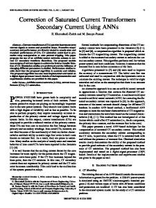
I. INTRODUCTION The applications of single-phase AC/DC converters are widely spread, starting with ballast circuits for CFL or LED lamps [1], [2] and finishing with rectifiers for railroad applications [3], [4]. As recent standards limits the harmonics content in the consumed current, the power factor correction circuits are utilized [5]–[8], that usually are implemented by means of diode rectifier and boost converter (see Fig.1.). However, the ability to control power flow in both directions makes AC/DC converters more versatile and demanded. It is requested by needs of contemporary households, where bidirectional AC/DC converters are utilized in harmonics compensation [9], energy storage applications [10], PV converters with snow melting functionality (that is relevant in Northern countries) [11], [12], electrical vehicle charger/dischargers (known as V2G-vehicle to grid concept) [13], [14].
D1
L1
D5
D3
C1 S1
D2
D4
Fig. 1. Mostly used single-phase unidirectional AC/DC converter’s topology.
S11
S21
S12
S22
S13
S23
C1 S1
S3
S1
C1
L1
L1
L1
C1
AC
AC C2
S2
S4
S2
AC
C2 S24
S14
(a)
(b)
(c)
Fig. 2. Widely spread bidirectional topologies: (a) half-bridge, (b) full-bridge and (c) multilevel type of converter.
978-1-4799-7462-7/14/$31.00 ©2014 IEEE
38
II. OVERVIEW OF CURRENT CONTROL METHODS
III. DEVELOPMENT OF SINGLE-SWITCH MODEL
Various number of switching techniques are known for shaping input current of switching mode power supplies [22]– [25]: delta modulation, hysteresis control, peak current control – just to name few. All of them require current sensor, which inherits limited bandwidth and introduces propagation delay in signal processing. Moreover, it is concluded in various publications [26]–[29] that instantaneous current measurement increases the cost and the size of a control system. Thus, the current sensorless control has been developed and evaluated mostly with traditional PFC circuit seen in the Fig. 1 [30]–[32]. Recently published article [33] has proposed bidirectional current sensorless control approach for the full-bridge converter. The comparison of mentioned sensorless control approaches is provided in Table I.
The main idea of the discussed current sensorless control is based on proper volt-second balance that shapes the inductor’s current in accordance with the reference signal of current value. The inductor’s voltage depends on conduction state of converter’s transistors. They are controlled by means of commutation signal, which is applied to one of two transistors depending on input voltage polarity and direction of power flow. Table II demonstrates commutated current paths and corresponding voltage applied to inductor. In order to track the changes of polarity of different variables in digital control system, simple Boolean function is defined as follows
⎧0, if x < 0 pos( x) = ⎨ . (1) ⎩1, if x ≥ 0 Now it is possible to write versatile inductor’s voltage equations that combine all variation as follows
TABLE I OVERVIEW OF DIFFERENT CURRENT SENSORLESS CONTROL PROJECTS Halfbridge
Topology
Boost
Boost
Boost
Immunity from nonsinusoidal voltage
-
-
√
√
√
DCM
-
-
-
-
√
CCM
√
√
√
√
√
25
160
50
40
25
Current control
Switching frequency [kHz] Inductance [mH]
4.65
1.2
4.56
4.6
*1
Capacitance [mF]
0.56
2.2
0.47
1.4
**(2x) 1
Power (W)
500
400
500
500
1000
AC voltage (RMS)
110
55
110
110
220
DC voltage
300
100
300
200
750
vL (d = 1) = [2 ⋅ (not ( pos(VAC ) xor pos(I M ))) − 1] ⋅ v AC + (not ( pos (VAC ) xor pos(I M ))) ⋅ vC 2
, (2)
− (not ( pos(VAC ) xor pos(I M ))) ⋅ vC1
. (3)
+ ( pos (VAC ) xor pos(I M )) ⋅ vC1 vL (d = 0) = [2 ⋅ (not ( pos(VAC ) xor pos (I M ))) − 1] ⋅ v AC − ( pos(VAC ) xor pos (I M )) ⋅ vC 2
The resulted single-switch model is presented on the Fig. 3. L1 d(t)=1
*Used in the simulation, but depends on the maximal acceptable current ripple of the capacitor in the physical converter **Used in the simulation, but should be selected in accordance with acceptable DC link voltage ripple in the physical converter
+
AC
d(t)=0
C1 +
C2 +
+
+
C2
C1
¬(AْB)·VC2
Proposed
(AْB)·VC1
[33] Fullbridge
(AْB)·VC2
[32]
¬(AْB)·VC1
[31]
(¬(AْB)·2-1)· VAC
[30]
Fig. 3. Equivalent single-switch model for half-bridge AC/DC converter (A=pos(VAC), B=pos(IM)).
As it can be noted from the table, the sensorless control is mostly used with low power converters (< 1 kW), where it is assumed that inductor operates only in continuous conduction mode (CCM) due to high switching frequency either bulky inductor. As a result, it leads to imprecise zero-crossing of inductor’s current, where inductor operates some switching cycles in discontinuous conduction mode (DCM), especially at light load condition. The avoidance of inductor’s DCM control is unacceptable for half-bridge topology due to the fact, that inductor is experiencing higher voltages during converter operation than in other topologies. This leads to more impetuous current rising and falling edges and, as a result, the inductor’s DCM period increases in comparison with other topologies. That is why it was defined in author’s previous publications [34] and [35] both DCM and CCM current control algorithms that provide precise current zero-crossing and smooth transition between DCM and CCM current peaks.
Fig. 4 demonstrates discontinuous and continuous current modes for input inductor that also has certain influence on average current calculation equations. iDCM_max,k
I [A]
iCCM_max,k
I [A]
iref(t)
iav g,k
iL(t) iref(t) iav g,k
Δ iref,k Δ iL,k
iL(t) iccm_min,k
t1,k
t [s]
t2,k Tsw (a) DCM
t1,k t2,k Tsw
t [s]
(b) CCM
Fig. 4. Inductor’s discontinuous and continuous current modes.
39
TABLE II COMMUTATED CURRENT PATHS IN AND CORRESPONDING INDUCTOR VOLTAGE
Input voltage is positive Input voltage is negative Transistor is conducting (d=1) Diode is conducting (d=0) Transistor is conducting (d=1) Diode is conducting (d=0) S1
-
vL
L1
Rectifier
+
C1
AC +
vAC iC2
S2
+
C2
S1 L1
Inverter
vC1
S1 L1 AC
iL
+
vAC
-
S2
vC2
+
+
C2
-
+ v - C1
S1 L1 AC +
iL
AC +
vAC
v L = −v AC + vC1
iC2 C2
S2
+ vC2 -
v L = −v AC − vC 2
v L (d = 1) ⋅ t1,k , L v (d = 0) − i DCM _ max,k = L ⋅ (t 2,k − t1,k ) , L where from t2,k is defined as t 2, k =
(5)
i DCM _ max,k ⋅ t 2,k
. (7) 2 ⋅ Tsw Substituting the t2,k in (7) by the definition in (6) and extracting transistor’s conduction time, the following control law is defined
iavg ,k ⋅ L ⋅ 2 ⋅ Tsw ⋅ v L (d = 0)
v L (d = 1) ⋅ (v L (d = 0) − v L (d = 1))
+ v - C2
.
vL
v L = −v AC − vC 2 + -
S1
vC1
L1 AC
iL
vAC
+
+
C1
vL
-
iC1
vC1
iL
iC2
S2
1 0.9 0.8 Dccm( k ) 0.7 0.6 0.5 Ddcm( k )0.4 0.3 0.2 0.1 0
(8)
v L (d = 1) v (d = 0) (9) ⋅ t1,k + L ⋅ (Tsw − t1,k ) . L L So, the transistor’s conduction time in CCM is defined as v L (d = 1) − v L (d = 0)
+ vC2 -
C2
+ -
S2
vC2
+ vC2 -
C2
v L = v AC − vC1
0
100
200
300
400
500
400
500
k
Δi ref ,k =
Δiref ,k ⋅ L − v L (d = 0 ) ⋅ Tsw
iC2 C2
(a) rectifier mode (IM=3.5 A)
The CCM control law can be extracted from the equation of volt-second balance during single switching period, which is defined as
t1,k =
C1
0.5 0.45 0.4 Dccm( k ) 0.35 0.3 0.25 Ddcm( k ) 0.2 0.15 0.1 0.05 0
(6)
The average current can be calculated as simple area of triangle divided by period as follows
t1,k =
S2
iL
Now it is possible to write the final equations for current sensorless control, using Boolean simplification formula ( A + A = 1 ) that results in definitions (11) and (12). Fig. 5 demonstrates analytical waveforms of DCM and CCM control laws for rectifier and inverter mode. The final commutation signal is selected as minimal value of DCM and CCM signals.
(4)
v L (d = 0) − v L (d = 1) . v L (d = 0)
i ref ,k = i avg ,k =
C2
v L = v AC + vC 2
The peak value of inductors current can be described by two formulas as follows i DCM _ max,k =
C1
-
-
+ v - C2
C2
AC +
S1 L1
+ vC1 -
S1 vL
vAC
S2
+ vC1 -
C1
vL
S2
L1
v L = −v AC + vC1
iL
vAC
-
+ v - C1
iL
vC2
v L = v AC − vC1
C1 iC1
vL
+
C1 iC1
vL
-
v L = v AC + vC 2
AC
-
iC1
-
-
vAC
+
C1
vL
L1 AC
iL
vAC
S1
vC1
0
100
200
300 k
(b) inverter mode (IM=−3.5 A)
.
(10)
Fig. 5. Analytical waveforms of duty cycle for current sensorless control (index k represents switching cycle number, fAC=50 Hz, fSW=25 kHz, VAC_M=311 V, VC1(t=0)=VC2(t=0)=375 V).
40
t1DCM ,k = t1CCM , k =
iref ,k ⋅ L ⋅ 2 ⋅ Tsw ⋅ [[2 ⋅ (not ( pos (VIN ) xor pos (I M ))) − 1]⋅ v AC − (not ( pos (VIN ) xor pos (I M ))) ⋅ vC1 − ( pos (VIN ) xor pos(I M )) ⋅ vC 2 ]
[[2 ⋅ (not ( pos(VIN ) xor pos(I M ))) − 1]⋅ vAC + (not ( pos(VIN ) xor pos(I M ))) ⋅ vC 2 + ( pos(VIN ) xor pos(I M )) ⋅ vC1 ]⋅ (− vC1,k − vC 2,k ) . (11) i ref , k ⋅ L − [[2 ⋅ (not ( pos (V IN ) xor pos (I M ))) − 1] ⋅ v AC − (not ( pos (V IN ) xor pos (I M ))) ⋅ v C1 − ( pos (V IN ) xor pos (I M )) ⋅ vC 2 ] ⋅ Tsw
. (12)
vC1, k + vC 2, k
IV. SIMULATION RESULTS
V. CONCLUSIONS
The PSIM software was used in order to implement current sensorless control algorithm, where “Simple C Block” was used to define mathematical equations. Fig. 6 demonstrates simplified power part of the simulation model.
The current-sensorless control for bidirectional half-bridge AC/DC converter allows eliminating the current sensor in the control system that potentially can reduce the cost and the size of the control system. The input current is shaped realizing proper volt-second balance that is described by 8 equations, as inductor voltage depends on transistor conduction state, input voltage polarity and direction of power flow. The singleswitch model allows reducing number of equations down to 2 that significantly simplifies implementation of the digital control system. The simulation results confirmed the ability to shape current by using current sensorless control. The average current value tracked the reference current signal both in discontinuous and continuous current mode, consequently, precise zero-crossing has been achieved. ACKNOWLEDGEMENTS This research work has been supported by Latvian Council of Science (Grant 673/2014 and Grant 416/2012).
Fig. 6. Power part of the simulation model.
The current source is attached to DC link. Initially it consumes 1 A, than at the time 0.1 s current source changes to −1 A, resulting in change of operation mode from rectifier to inverter, as it can be seen from simulation results in Fig. 7. I_pfc
AVGX(I_pfc,40u)
REFERENCES [1]
F. Sichirollo, S. Buso, and G. Spiazzi, “Analysis and optimization of the AHB-flyback topology for solid state lighting applications,” in IECON 2011 – 37th Annual Conference of the IEEE Industrial Electronics Society, 2011, pp. 2895–2900. [2] A. Suzdalenko and I. Galkin, “Choice of power and control hardware for smart LED luminary,” in Electronics Conference (BEC), 2010, 2010, pp. 331–334. [3] A. Ben Youssef, S. K. El Khil, and I. Slama-Belkhodja, “State ObserverBased Sensor Fault Detection and Isolation, and Fault Tolerant Control of a Single-Phase PWM Rectifier for Electric Railway Traction,” IEEE Trans. Power Electron., vol. 28, no. 12, pp. 5842–5853, Dec. 2013. [4] R. J. Hill, “Electric railway traction. Part 3: Traction power supplies,” Power Eng. J., vol. 8, no. 6, pp. 275–286, Dec. 1994. [5] O. Stihi, “A single-phase controlled-current PWM rectifier,” IEEE Trans. Power Electron., vol. 3, no. 4, pp. 453–459, Oct. 1988. [6] A. Suzdalenko, A. Stepanov, and I. Galkin, “Choice of power factor corrector for effective operation of MicroGrid and its elements,” in 2010 International School on Nonsinusoidal Currents and Compensation, 2010, pp. 234–238. [7] I. Galkin, A. Stepanov, and P. Suskis, “Selection of power factor corrector for modular uninterruptable power supply system,” in Proceedings of 14th International Power Electronics and Motion Control Conference EPE-PEMC 2010, 2010, pp. T13–17–T13–21. [8] Y. Denisov and S. Stepenko, “Power Factor Corrector Based on Parallel Quasi- Resonant Pulse Converter with Fast Current Loop,” Electr. Control Commun. Eng., vol. 3, no. 1, pp. 5–11, Jan. 2013. [9] G. Wrona and M. Jasinski, “AC-DC Converter with Asymmetrical Higher Harmonics Compensation Function in Sustainable AC Grid,” Electr. Control Commun. Eng., vol. 2, no. 1, pp. 5–13, Jan. 2013. [10] F. A. Inthamoussou, J. Pegueroles-Queralt, and F. D. Bianchi, “Control of a Supercapacitor Energy Storage System for Microgrid Applications,” IEEE Trans. Energy Convers., vol. 28, no. 3, pp. 690–697, Sep. 2013. [11] N. Takehara and N. Manabe, “PHOTOVOLTAIC POWER GENERATING SYSTEM,” US006093885A2000.
Vin/311*7
10 5 0 -5 -10 Vc1+Vc2 790 780 770 760 750 740 Idc 1 0.5 0 -0.5 -1 0.06
0.08
0.1
0.12
0.14
0.16
Time (s)
Fig. 7. Simulation results (current source changes from 1 A to −1 A at time 0.1 s).
41
[27] F. Javier Azcondo, A. de Castro, V. M. Lopez, and O. Garcia, “Power Factor Correction Without Current Sensor Based on Digital Current Rebuilding,” IEEE Trans. Power Electron., vol. 25, no. 6, pp. 1527–1536, Jun. 2010. [28] A. Garcia, A. de Castro, O. Garcia, and F. J. Azcondo, “Pre-calculated duty cycle control implemented in FPGA for power factor correction,” in 2009 35th Annual Conference of IEEE Industrial Electronics, 2009, pp. 2955–2960. [29] M. Rodriguez, V. M. Lopez, F. J. Azcondo, J. Sebastian, and D. Maksimovic, “Average Inductor Current Sensor for Digitally Controlled Switched-Mode Power Supplies,” IEEE Trans. Power Electron., vol. 27, no. 8, pp. 3795–3806, Aug. 2012. [30] H. Chen, “Single-Loop Current Sensorless Control for Single-Phase Boost-Type SMR,” IEEE Trans. Power Electron., vol. 24, no. 1, pp. 163–171, Jan. 2009. [31] W. Zhang, S. Member, G. Feng, Y. Liu, and S. Member, “A Digital Power Factor Correction ( PFC ) Control Strategy Optimized for DSP,” vol. 19, no. 6, pp. 1474–1485, 2004. [32] H.-C. Chen, C.-C. Lin, and J.-Y. Liao, “Modified Single-Loop Current Sensorless Control for Single-Phase Boost-Type SMR With Distorted Input Voltage,” IEEE Trans. Power Electron., vol. 26, no. 5, pp. 1322–1328, May 2011. [33] H. Chen and J. Liao, “Bidirectional Current Sensorless Control for the Full-Bridge AC / DC Converter With Considering Both Inductor Resistance and Conduction Voltages,” vol. 29, no. 4, pp. 2071–2082, 2014. [34] A. Suzdalenko and I. Galkin, “Analysis of Transformerless Bidirectional AC/DC Converter Based on Double Half-Bridge Topology with NonCommutating Neutral Wire,” in Proceedings of 54th International Scientific Conference of RTU, 2013, pp. P33.1–P33.6. [35] A. Suzdalenko, “Current Sensorless Control of Front-end Bidirectional AC/DC Converter Based on Half-bridge Topology,” Electr. Control Commun. Eng., vol. 4, no. 1, pp. 19–25, Jan. 2013.
[12] Y. Kyung-shick, L. Koo, H. Chang-Seon, K. Woo-Jin, Y. Sun-A, and C. Yong-Hyun, “SNOW REMOVAL DEVICE FOR A PHOTOVOLTAIC POWER GENERATION SYSTEM,” WO20111491162010. [13] B. Droste-Franke, B. P. Paal, C. Rehtanz, D. U. Sauer, J.-P. Schneider, M. Schreurs, and T. Ziesemer, Balancing Renewable Electricity, 1 edition., vol. 40. Berlin, Heidelberg: Springer Berlin Heidelberg, 2012, p. 301. [14] O. C. Onar, J. Kobayashi, D. C. Erb, and A. Khaligh, “A Bidirectional High-Power-Quality Grid Interface With a Novel Bidirectional Noninverted Buck–Boost Converter for PHEVs,” IEEE Trans. Veh. Technol., vol. 61, no. 5, pp. 2018–2032, Sep. 2012. [15] I. Cvetkovic, D. Dong, W. Zhang, L. Jiang, D. Boroyevich, F. C. Lee, and P. Mattavelli, “A testbed for experimental validation of a lowvoltage DC nanogrid for buildings,” in 2012 15th International Power Electronics and Motion Control Conference (EPE/PEMC), 2012, pp. LS7c.5–1–LS7c.5–8. [16] H. Kakigano, M. Nomura, and T. Ise, “Loss evaluation of DC distribution for residential houses compared with AC system,” 2010 Int. Power Electron. Conf. - ECCE ASIA -, pp. 480–486, Jun. 2010. [17] D. Dong, I. Cvetkovic, D. Boroyevich, W. Zhang, R. Wang, and P. Mattavelli, “Grid-Interface Bidirectional Converter for Residential DC Distribution Systems—Part One: High-Density Two-Stage Topology,” IEEE Trans. Power Electron., vol. 28, no. 4, pp. 1655–1666, Apr. 2013. [18] H.-S. Kim, M.-H. Ryu, J.-W. Baek, and J.-H. Jung, “High-Efficiency Isolated Bidirectional AC–DC Converter for a DC Distribution System,” IEEE Trans. Power Electron., vol. 28, no. 4, pp. 1642–1654, Apr. 2013. [19] F. Jauch and J. Biela, “Single-phase single-stage bidirectional isolated ZVS AC-DC converter with PFC,” in 2012 15th International Power Electronics and Motion Control Conference (EPE/PEMC), 2012, pp. LS5d.1–1–LS5d.1–8. [20] J. Lee, G. Moon, and M.-J. Youn, “Design of high quality AC/DC converter with high efficiency based on half bridge topology,” in PESC 98 Record. 29th Annual IEEE Power Electronics Specialists Conference (Cat. No.98CH36196), 1998, vol. 2, pp. 1054–1060. [21] A.N. Arvindan and V.K. Sharma, “Simulation Based Performance Analysis of High Frequency Improved Power Quality Bi-Directional Multilevel AC-DC Converters,” in 2006 IEEE Power India Conference, 2006, pp. 559–566. [22] L. Rossetto, G. Spiazzi, and P. Tenti, “Control techniques for power factor correction converters,” in Proc. PEMC’94, 1994, pp. 1–9. [23] N. Mohan, T. M. Undeland, and W. P. Robbins, Power Electronics: Converters, Applications, and Design, 3 edition. Wiley, 2002, p. 824. [24] H. Choi, “Interleaved Boundary Conduction Mode (BCM) Buck Power Factor Correction (PFC) Converter,” IEEE Trans. Power Electron., vol. 28, no. 6, pp. 2629–2634, Jun. 2013. [25] O. Husev, D. Vinnikov, C. Roncero-Clemente, and E. Romero-Cadaval, “New hysteresis current control for grid connected single-phase threelevel quasi-Z-source inverter,” in 2014 IEEE Applied Power Electronics Conference and Exposition - APEC 2014, 2014, pp. 1765–1770. [26] T. Qi, L. Xing, and J. Sun, “Dual-Boost PFC Converter Control Without Input Current Sensing,” in 2009 Twenty-Fourth Annual IEEE Applied Power Electronics Conference and Exposition, 2009, pp. 1855–1861.
Alexander Suzdalenko received B. Sc (2007), M. Sc. (2009) and Dr. sc. ing. (2013) degree in Riga Technical University in the field of electrical engineering. His research interests are related to design and control of power electronics converters. He contributed to intelligent household energy systems, studying the power balancing approaches, non-intrusive load monitoring algorithms and advantages of usage of LEDs. He has practical experience, working for two years in scientific and production association ELLAT Ltd as electronic device engineer. He is IEEE member since 2010 and joins PELS, IES and IAS societies. Postal adress: Postal address: Riga Technical University – Faculty of Power and Electrical Engineering, Azenes street 12 building 1, room 515, Riga LV-1048, Latvia. E-mail:
[email protected]
42