ABCM Symposium Series in Mechatronics - Vol. 1 - pp.58-67 Copyright © 2004 by ABCM
DEVELOPMENT OF SOFTWARE TO SIMULATE ROBOTICS MANIPULATORS Aline Souza de Paula EE/UFRJ – Departamento de Engenharia Mecânica C.P. 68503 – CEP 21945-970 – Rio de Janeiro – Brasil
[email protected]
Victor Cesar Vargas da Silveira Cunha Cruz COPPE/UFRJ – Programa de Engenharia Mecânica
[email protected]
Max Suell Dutra COPPE/UFRJ – Programa de Engenharia Mecânica
[email protected] Abstract. This paper consists of the development of a program capable to model the kinematics of robotics manipulators aiming at the supply of a tool to facilitate the project of these mechanisms. This program was written in the language Java facilitating your interface with the Internet and with VRML. The kinematics modeling is of great importance for the study of robotics manipulators and fundamental for its project and construction. In this modeling the direct kinematics was included, where the position of the endeffector in the space is function of the movements of its joints, and the inverse kinematics, that consists of the determination of the joint variables corresponding to a given end-effector position and orientation. As a result of this work it was made a simulation of the direct and inverse kinematics of robotics manipulators with several configurations of joints, allowing a graphic visualization of the obtained results Keywords. Kinematics, Simulations, Robotics Manipulators, Software
1. Introduction Long-distance education has been, in many countries, a viable alternative to take care of social interests and necessities, to provide a professional improvement, to facilitate the knowledge access to pupils with difficulty to attend a university course. The Internet, in turn, consists in the more adjusted media to this education type, in view of its world -wide reach, the low involved costs in the educational material needed and the possibility of the professor-pupil and pupil-pupil communication in a fast and efficient form (D’Aquino, 2002) Moreover it is important the simulations use in education in specific areas, as ni engineering, is long date recognized. The simulators use motivates the learning much more than the traditional education methods, once the main objective is the direct student participation (Maia, 2000). Considering the reasons above, the software presented in this paper carries through a graphic simulation controlled by the user of some predefined robotics manipulators, being able to run on the Internet. The program was written in Java language, in the form of an applet, and VRML 2.0. Where VRML 2.0 (Virtual Reality Modeling Language) was selected as the modeling language for the 3D environment and Java was chosen as the programming language to implement the user’s control. Both can be incorporated in a HTML document being executed by an Internet navigator. The programming language Java is independent of the used platform and is an object oriented language. This work platform was chosen in principal because two reasons: the existent interface between Java and VRML, and the existing possibility of both to be implemented on the Internet, the last reason is of great interest in view of the long distance education. The simulations are carried through from the inverse kinematics analyses. The used method to do this analyze, in turn, needs the direct kinematics result. The simulations built permits that the results can be visualized graphically in 3D, permitting a more real vision of the mechanisms movement and helping in the project and constructions of them. A related work of the use of Java/VRML simulators was the implementation by the DLR (Deutsches Zentrum für Luft- und Raumfahrt). In order to carry through a teleoperation control, the system prevents problems of delay and provides a better accomplishment of the tasks. This system was experimented in ROTEX (Roboter Technology Experiment) that was flown on space shuttle COLUMBIA (STS 55). In this operational experience a multisensory robot on board successfully worked in several modes, teleoperated by astronauts, as well as in different telerobotic ground control modes. While ROTEX was flown, its movements could be visualized and controlled using the simulation built (DLR, 2003). In the next section Java and VRML basics interface is described and the interacting type is explained. Then the kinematics analyze is done, including the direct and the inverse. The configurations of the chosen manipulators are presented, where two types of joints were used, prismatic and rotation. Finally the graphic structure and its results are presented.
2. Interacting Java and VRML There are two forms of interacting Java and VRML, one intern and another extern. In the first one a Script node program is used, Javascript or VRMLscript (which is actually a subset of Javascript). A script node is used to program behavior in a scene. Each script node has an associated programming language code, referenced by the url field, that is executed to carry out the script node's function (Carrey et al., 2002). In this kind of programming it is able to receive and process events, the eventIn, and to generate events in response to the incoming ones, the eventOut. The procedure with the events occurred are specified in the program code, not in the scripting. To indicate the scripting language, the field value starts with the script code. For example, a program written in VRMLscript controlled by Java, where there is a blue ball in the screen and when its surface is clicked it becomes red. There is as eventIn -> clicked ball and as eventOut -> color change (Fig. (1)). The procedure with the events is specified in the Java program, Color.java that after being compiled becomes Color.class. #VRML 2.0 (Part of the code that create the graphical structure) DEF ColorScript { url "Color.class" eventIn SFBool clicked eventOut SFColor newColor field SFBool on FALSE } Figure 1. The structure of a VRML program The external interface EAI (External Authoring Interface), proposed by Silicon Graphics, Inc. (SGI, 2003), defines the set of functions on the VRML browser that the external environment can perform to affect the VRML world. In other words, it defines how an external program in process can manipulate the VRML browser. In this interface, Java controls the VRML world by handling events to and from nodes. A VRML world is defined by nodes , which are types of object that have field (property of objects) and field values that describe their attributes, and are usually nested (an overall nesting of all nodes defines the scene graph). To make these nodes available to the external interface they have to be DEF’d (defined) in the VRML file (Fig (2)). The DEF name capability in VRML is a syntactic construct that allows nodes to be used and routes to be defined between nodes in the same VRML file scope (Finlayson, 2002). The nodes are controlled by Java (or other external languages) through the Browser.getNode( ) method. #VRML V2.0 utf8 DEF NODE Transform{} Figure 2. Creating a node and making it available to the external interface The EAI is being standardized by VRML Working Group (EAI working Group, 2002), but it is already implemented in some browsers. Most of the existent browsers support javaScript and VRMLscript and some also support Java. In relation to the differences between the internal and external interfaces, it can be said that the browser controls the events when the script node program is used, while in an application using EAI the Browser actuates as a direct controller (Baerten et al., 1999). The interacting type depends sometimes on the programmer’s style. Some statements try to clarify the functional difference between them, using the internal interface for behaviors purely within the world and the external interface for behaviors linking outside (Regan, 2002). Use the script node to deal with behaviors of individual objects in a VRML world and the external interface when creating integrated multi-media presentations (Marrian, 2002). The first one is used mostly for events like clicking objects, timer events, events generated by others script nodes. When constructing more complex scenes that involve simulations, animations the external interface is more appropriated. The external interface was chosen based on the possibility to run in the same time an applet and a VRML browser using only one Web page. The proposed software consists of a VRML world controlled by Java where exists an applet that runs in a Web page. It is able to run in any platform that supports Java and a VRML browser as Cortona® (this browser has to support the EAI).
3. The Kinematics Modeling In robot simulations and projects some analyses need to be done. One of them is the kinematics analysis, whose purpose is to carry through the study of the movements of each part of the mechanism and its relations between itself. The kinematics analyses is divided in direct and inverse kinematics. The direct kinematics consists to find the position of the end-effector in the space knowing the movements of its joint, and the inverse kinematics consists of the determination of the joint variables corresponding to a given end-effector position and orientation (Siciliano, 2000) (Fig. (3)). Direct Kinematics Geometric Parameters
Joints movements
Position and orientation of the end-effector
Inverse Kinematics
Figure 3. Kinematics Diagram block 3.1. Direct Kinematics A rigid body is completely described in space by its position to a reference frame (translation) and its orientation (rotation) (Cunha Cruz, 2002). Many methods can be used in the direct kinematics calculation. The Denavit-Hartenberg analyses is one of the most used, in this method the direct kinematics is determinate from some parameters that have to be defined, depending on each mechanism. However, it was chosen to use the homogeneous transformation matrix. In this analyze, once it is easily defined one coordinate transformation between two frames, where the position and orientation are fixed one with respect to the other (Fig. (4)), it is possible to work with elementary homogeneous transformation operations. z
y {B}
z
x
{A} y x Figure 4. {B} Referential rotated and translated in respect to {A} referential. The B referential can be written with respect to the A referential though translations and rotations that can be represented by homogeneous transformations matrices. The use of homogeneous transformation matrix leads to the same result gotten in the Denavit-Hartenberg analyzes. Its application is simplest but in complex mechanisms it seems to be more laborious (Naka, 2001). The homogeneous transformation matrix is a 4 by 4 augmented matrix that transports a vector expressed in homogeneous coordinates from one coordinate frame to another (and gives the orientation and position of this vector). This matrix can be divided in 4 sub-matrices (Fig. (5)). Representation of the orientation of the body
R3 x3 T= f 1x 3 Figure 5. Homogeneous transform matrix.
p3 x1 s1x1
=
n x n y nz 0
sx sy sz 0
ax ay az 0
Body point position
px p y pz 1
Where the 3 by 3 augmented matrix, R3x3 , represents the rotation, the 3 by 1 augmented matrix, P3x1 , represents the translation; the f1x3 represents the perspective transformation and S1x1 is the factor of universal scale. The direct kinematics is made from the composition of homogeneous transformation matrices, where each translation (prismatic joint) or rotation (rotation joint) correspond to one 4 by 4 augmented matrix: i
T
j
=i
T
i +1
.i+1 T i+ 2 .... j−1 T j
(1)
The anthropomorphic arm (Fig. (6)) analyze will be developed as an example. This mechanism is composed by 3 rotation joints as shown in the figure.
a3 a2 z
θ3 q
θ2
a1 y
θ1 x
Figure 6. Anthropomorphic arm structure The links lengths can be treated as translations, and each transformation matrix will be composed by the multiplication of a rotation matrix and a translation matrix. The direct kinematics is calculated by the composition: 0
T3 = 0T1.1 T2 . 2 T3
(2)
where:
Cos[θ1 ] − Sin[θ1 ] 0 Sin[θ ] Cos[θ ] 0 0 1 1 T1 = R( Z ,θ1 ).T (Z , a1 ) = 0 0 1 0 0 0 0 0 1 0 Cos [θ ] − Sin[θ ] 2 2 1 T2 = R( X ,θ 2 ).T (Y , a 2 ) = 0 Sin[θ 2 ] Cos [θ 2 ] 0 0 0
0 1 0 0 . 0 0 1 0 0 1 0 0 . 0 0 1 0
0 0 1 0 Cos [θ ] − Sin[θ ] 3 3 2 T3 = R( X , θ 3 ).T (Y , a 3 ) = 0 Sin[θ 3 ] Cos[θ 3 ] 0 0 0
0 1 0 0 . 0 0 1 0
0
0
1
0
0
1
0
0
0
0
1 0 0
0 1 0
0
0
1 0 0
0 1 0
0 0 (3) a1 1 0 a2 (4) 0 1 0 a 3 0 1
(5)
The composition of these matrices gives the resultant matrix:
− Cos [θ 2 + θ 3 ]Sin[θ 1 ] Sin[θ 1 ]Sin[θ 2 + θ 3 ] Cos [θ 1 ] − ( a 2 Cos [θ 2 ] + a 3 Cos [θ 2 + θ 3 ])Sin[θ 1 ] Cos [θ + θ ]Cos [θ ] − Cos [θ ]Sin[θ + θ ] Sin[θ ] (a Cos [θ ] + a Cos [θ + θ ])Cos [θ ] 2 3 1 1 2 3 1 2 2 3 2 3 1 0 T3 = Sin[θ 2 + θ 3 ] Cos [θ 2 + θ 3 ] 0 a1 + a 2 Sin[θ 2 ] + a 3 Sin[θ 2 + θ 3 ] 0 0 0 1 (6)
Considering the adopted frame orientation,
θ 1 is given in the counter-clockwise direction from axle y, in other
words, θ 1 is zero in x = 0. To carry through the anthropomorphic arm direct kinematics solution in the program, it is used the created function: anthropomorphic_direct
(θ 1 , a1 ,θ 2 , a2 ,θ 3 , a 3 )
3.2. Inverse Kinematics The inverse kinematics considers that given a specific trajectory desired it is necessary to determine the values that the mechanism must assume to carry through this way. As it can be perceived the solution of this kinematics problem is more important for robotic systems, once from this study it is possible to carry through the control of all system, from each action actuator determination. Its solution, however, is much more complex than direct kinematics there isn’t any global analytical solution method. Each manipulator needs a particular method considering the system structure and restrictions. As in the direct kinematics the anthropomorphic arm analysis will be developed as an example. The solution involves the use of the direct kinematics result. It was used the geometric and algebraic solutions. The first joint movement, defined by θ 1 , can be calculated using geometric parameters only:
y θ 1 = arctg[ ] x
(7)
Using the X, Y and Z resultants gotten in the direct kinematics:
X = −( a2 Cos[θ 2 ] + a3 Cos[θ 2 + θ 3 ]) Sin[θ 1 ] Y = (a 2 Cos[θ 2 ] + a3Cos[θ 2 + θ 3 ])Cos[θ1 ] Z = a1 + a2 Sin[θ 2 ] + a3 Sin[θ 2 + θ 3 ]
(8)
Z1 = Z − a1 The simplified equation is gotten:
X 2 + Y 2 + Z1 = a2 + a3 + 2a2 a3Cos[θ 3 ] 2
2
2
(9)
Thus Cos [ θ 3 ] is given by:
X 2 + Y 2 + Z1 2 Cos[θ3 ] = 2 a 2 a3
(10)
And Sin [ θ 2 ] by:
Sin[θ 2 ] =
Z1 a3 Cos[θ 3 ] + a 2
(11)
There are four solutions for each X, Y and Z given coordinates, the result above is one of them and was chosen to build the simulation. The built function code to solve the inverse kinematics is: anthropomorphic_inverse (X, Y, Z, a1, a2, a3) Differently of the direct kinematics, where all manipulators solution is done by the composition of homogeneous matrices, in the inverse analyze each manipulator has a different solution, and the anthropomorphic arm study shown in this paper is a particular case and could be solved in different forms, methods. 4. Chosen Manipulators Configurations The manipulators configurations chosen for this work are very known and normally found in robotic books. This is explained concerning that the proposal of this project is exactly to help in the education. This work intends to make the study become more concrete, once students can visualize the calculations and analyses they do.
4.1. Planar manipulator As the first manipulator, there is a three-link planar arm (Fig. (7)). Composed by 3 rotation joints, with all rotation about z axle, the lin ks are all lying in the plane. The direct kinematics is calculated from the composition of three equals homogeneous transformation matrix:
i
Ti +1
Cos[θ1 ] − Sin[θ1 ] Sin[θ ] Cos[θ ] 1 1 = 0 0 0 0
0 a i Cos[θ i ] 0 a i Sin[θ i ] 1 0 0 1
(12)
y a3
a2
θ3
θ2
a1
θ1
x
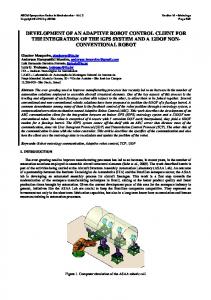
Figure 7. Three-link planar arm. 4.2. Anthropomorphic Arm Another chosen manipulator was the anthropomorphic arm (Fig (6)), which direct and inverse kinematics have been analyzed above. It can be noticed that this mechanism corresponds to a two-link planar arm with an additional rotation about the z (the frames have been illustrated in the figure). The mechanism consists of three rotation joints, the first rotation about the z, followed by two rotations about the x. 4.3. Gantry Manipulator The gantry manipulator (Fig. (8)) is composed only by prismatic joints, there are 3 joints each one translating in one axle. Such a structure allows obtaining a large volume workspace and manipulating objects of gross dimensions and weight, it is very used in industries for material handling and assembly.
Figure 8. The Gantry Manipulator.
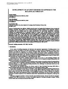
4.4. Standford Manipulator The standford Manipulator is composed by a spherical arm, that consists of two rotations and one translation; and a spherical wrist, that consists of three rotations. The result is a manipulator that consists of 5 rotation joints and one prismatic joint, as shown in the figure (Fig. (9)):
Figure 9. The Standford manipulator, where R corresponds to rotation joint and P to prismatic joint. 5. Software Structure The software is composed of four parts: a math library, an applet; a 3D graphical modeling and an interface between Java and VRML. These parts consist of three modules once the applet and the control are in the same Java code. 5.1. Math Library The math library was written in the Java language (Fig. (10)). In this library was defined a 4x4 augmented matrix, 4x4 identity matrix and the 4x4 matrix multiplication function. Using these concepts, functions to translate (along the X, Y, Z axes) and rotate (about the X, Y, Z axes) objects were built. As well as functions that carry through the direct kinematics, where by the joint movements and geometric parameters the result of the end-effector position (X, Y and Z axes) and orientation is calculated. In spite of already having classes built in Java that defines a 4x4 matrix and translates or rotates objects, build a new library with this functions gives procedures format more appropriated to get the information as it’s needed. For example, in the functions built after rotating and translating vectors (or objects) there is a 4x4 matrix as result, which gives us not only the positions of the end-effector but the orientation as well. While in the existents functions in the end of the operation it is only possible to get the final position, there isn’t further information as the orientation.
public class Matrix3D{ float e00, e01, e02…
//matrix components definition
public void multiply(entry parameters) {… } //function to multiply 4 by 4 matrices public void identity(entry parameters) {… } //function to create a identity matrix
…
//functions to rotate and translate objects
public void anthropomorphic(entry parameters) {… } //anthropomorphic arm direct kinematics
…}
//others manipulators
Figure 10. Structure of the built math library.
5.2. Visual Interface The visual interface was made in form of an applet, which is incorporated in a HTML document. Basically it is a HTML document (Fig. (11)), with buttons, textfields (boxes for text entry) and others utilities to get parameters entry and write back the result, the output. These commands are written in a java class that also makes the use of the Matrix3D class to carry through the direct kinematics and print the results. Robotics Manipulators Simulators Figure 11. A typical implementation of a simple HTML document 5.3. VRML world The VRML world is a simple VRML document with nodes declared as DEF. Once defined these nodes, Java is able to control it using the external interface (EAI). Like it was explained in the Interacting Java and VRML section, java controls the 3D environment with the Browser.getNode( ) method, modifying the graphical modeling without changing the VRML code. At first a simple VRML program was written to create the 3D environment, but the possibility to build the graphical part in SolidWorks is being studied. The SolidWorks can convert its document into VRML 1.0 and a specific converter makes this document a VRML 2.0 world. The structure of a written VRML document and a converted VRML document is the same, but while the last one has its graphical part based on coordinates the other is composed by successive codes (Fig (12)). #VRML V2.0 utf8
#VRML V2.0 utf8
... Appearance { material Material { ambientIntensity 0.752941 specularColor 0.662588 0.662588 0.662588 emissiveColor 0.158118 0.158118 0.158118 shininess 0.21 transparency 0 } } geometry IndexedFaceSet { coord Coordinate { point [ -0.029953 0 0.001672, -0.02983 0 -0.003194, -0.029585 -0.004693 0.001651, ...........]} (a)
... appearance DEF BallApp Appearance { material Material { ambientIntensity 0.25 diffuseColor 0.381944 0.748016 0 specularColor 0.963636 0.963636 0.963636 emissiveColor 0 0 0 shininess 0.981818 transparency 0 } } geometry DEF BallSphere Sphere {
…
(b)
Figure 12. (a) a VRML world converted from a SolidWoks program and (b) a program written in the VRML language. As it can be seen in the figure the beginning of the programs are similar (a), where the appearance is defined, but the geometric part is completely different (b). While in the constructed VRML there is just a Sphere code to draw a ball, in the converted VRML file there are many coordinates (it is not possible to show all coordinates once it involves lots of pages). The advantage to use the Solid Works to build the 3D environment is that the software offers lots of facilities to draw solid bodies. Its use to build manipulators is more specific than the VRML language.
5.4. Final Result Combining these parts, the program is built. In the first page of the program it can be chosen one of the four manipulators presented and the kinematics analyze type, direct or inverse. After choosing, a new page is open (Fig. (13)) in accordance with what was chosen.
Figure 13. Anthopomorphic Manipulator shown in the VRML browser controlled by a Java applet, both incorporated in a HTML document. Figure (13) corresponds to the anthropomorphic arm and direct kinematics chooses. In this case once the parameters entry, links lengths and rotations, are typed it is possible to get the X, Y, Z resultants and to visualizate the manipulator configuration. The inverse kinematics window is similar, but the entry parameters and the output are inverse. The entries are the X, Y, Z values and the links lengths (geometric parameters), and as a result it is gotten the joints variables, as well as the manipulator configuration shown by the VRML browser. The simulation is made from the inverse kinematics, where a trajectory (X, Y, and Z values that varies in the time) is the parameter entry and the answer is the manipulator animation shown by the VRML browser, where the end-effector follows the trajectory. 6. Conclusion The ideas and results presented in this paper are the first stage of the software development, there are many ideas to be implemented. So far four manipulators had been implemented in the program, but there is the intention to implement others. Besides that, there is the intention of making available to the user to build his own manipulators. In this case it would be possible to choose among rotation and prismatic joints (rotations and translations) and giving the geometric parameters, links lengths, the program would be able to calculate the direct kinematics and then show the configuration in the VRML browser. This generalization is possible from the concepts already formulated shown in this paper (Java and VRML interface; kinematics analyze; use of mathematical methods, as multiplication of matrices, in Java) and programming language knowledge. Moreover, the Java and VRML platform offers much more resources beyond the ones that had been used, like for example, remotely operating a simulated or real robot, what would be of great interest to implement in our lab. 7. References Bearten, H., Reeth, F. V., 1999, “Using VRML and JAVA to visualize 3D algorithms in computer graphics education”, Computer Networks and ISDN Systems, Vol. 30, pp. 1833-1839. Carrey, R., Bell, G., “Annotated VRML 97 reference”, website URL: http://www.web3d.org/resources/vrml_ref_manual. Accessed in August 2002. Chan, M. C., Griffith, S. W., Iasi, A. F., “Java 1001 dicas de Programação”, Makron Books, ISBN 85.346.0895-4, 1999, Brazil. Cunha Cruz, Victor Cesar V. S. “Estudo para o Desenvolvimento de um robô Cirúrgico Minimamente Invasivo”, Final Project DEM/EE/UFRJ/ 2002. D’Aquino, E. A., 2002, “Um simulador e o projeto de uma bancada experimental de pêndulo simples e invertido voltados para o ensino assistido por computador de controle nebuloso”, M. Sc. Thesis COPPE/PEM/UFRJ.
EAI working Group, 1999, website URL: http://www.web3d.org/WorkingGroups/vrml-eai/. Accessed in December 2002. Finlayson, R. A., “VRML 2.0 EAI FAQ”, website URL: http://www.frontiernet.net/~imaging/eaifaq.html. Accessed in September 2002. DLR website URL: http://www.robotic.dlr.de/TELEROBOTICS/rotex.html. Accessed in February 2003. L. Sciavicco, B. Siciliano, “Modeling and Control of Robot Manipulators”, Springer-Verlag, 2nd Edition, ISBN 185233-221-2, London, 2000. Maia, E. V., Calixto, J. M. F., Silva, R. P., et al., 2000, “Sobre uma metodologia de ensino de engenharia de estruturas através da Web”, Proceedings of the Brazilian Congress of Mechanical Engineering, 2000, pp. 56-63, Natal (RN), Brasil. Naka, M. H., 2001, “Estudo e projeto de uma mão mecânica de cinco dedos, com atuadores utilizando material com memória de forma”, M. Sc. Thesis COPPE/PEM/UFRJ. Regan, T., Marrian, C., website URL: http://www.frontiernet.net/~imaging/eaifaq.html. Accessed in September 2002. SGI, website URL: http://www.sgi.com/ . Accessed in January 2003.