Development of Verifiable Programs - Application of an Approach based on Executable Object-Oriented Specifications Natasha Sharygina1,3, James C. Browne2, and Delbert Tesar3 1
Bell Laboratories, 600 Mountain Ave., Murray Hill, NJ, USA 07974
[email protected] 2 The University of Texas at Austin, Computer Science Department, Austin, TX, USA 78712-0050
[email protected] 3 Robotics Research Group, The University of Texas at Austin, Austin, TX, USA 78712-1100 {natali,tesar}@mail.utexas.edu
Abstract Combining validation by testing with verification by formal methods offers great potential for development of robust and reliable object-oriented software systems. However, formal verification cannot be readily applied to software developed with conventional object-oriented development methods. This paper presents the first phase of a two-phase approach for development of object-oriented software systems which combines validation of OOA models formulated in xUML (an executable subset of UML[18],[24]) with formal verification through model checking. The second phase, application of model checking to the validated OOA model has been presented separately [22]. Model checking is accomplished by translating the validated OOA model to the COSPAN, automaton-based model checking system [5]. This paper defines, describes and illustrates an OOA model construction process leading to OOA models which can be both validated and verified. This process leads to efficient designs, which minimizes complexity of the resulting computer-controlled systems. Since OOA models in xUML are executable they can be validated by testing using simulation. Finally, since the OOA model complexity level is much less than the procedural programs to which they are translated, model-checking can be applied to the validated OOA model. We demonstrate the approach by applying it to reengineering of a NASA robotic system where testing and maintenance had been obstructed by complexity. A comparative analysis between the original robotic system, that was constructed following the Booch methodology [1], and the redesigned system is given. A number of inefficiencies and flaws in the original design which would have precluded model checking were found. An OOA model to which model checking has been successfully applied resulted from the redesign. Keywords: Object-Oriented Design and Analysis of Complex Software Systems, Formal Verification, Design for Verification, Integration of Model Checking with ObjectOriented Techniques.
1 Introduction Formal methods, in particular model checking, are increasingly being used to automatically establish the correctness of (and to find flaws in) finite-state systems, such as descriptions of hardware and protocols. Most
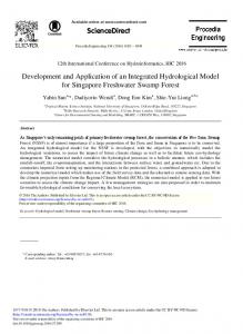
software systems however are not directly amenable to finite-state verification methods. The state spaces of procedural programs are typically dynamic and unbounded. Abstract models of the programs to which model checking can be applied are not validated so that model checking is impeded by an explosion of errors. In this paper we present and apply the first phase of a twophase OOA-based methodology (Figure 1) for software development based on representation of the software system as an executable OOA model, validation by simulation, application of model checking to the OOA model and translation of the validated and verified OOA model to a procedural language. The integrated environment is built on the xUML (xUML [18] is a subset of UML [19] with an executable semantics) version of the Shlaer-Mellor OOA (SM OOA) methodology [24] and the COSPAN, automaton-based model checking system [5]. The integrated methodology is based on the following premises: • the validated and verified software system must be fully functional (must be developed in an executable form) and efficient; • verification must be executed on an abstract model since a program which is fully functional and efficient will be far too complex for application of formal verification; • verification is practical only when the design model has been validated by conventional testing and is largely correct; • verification can therefore only be applied to a validatable (executable) specification; • the abstract model must therefore be validated before verification can be applied; • therefore, code development must be based on an executable model specification; • xUML is an executable specification language; • if verification is to be meaningful, the executable specification must be compilable to an efficient final program. • xUML is compilable.
This paper reports results of a project that has been conducted at Bell Laboratories and The University of Texas at Austin (where the ideology and support tools were developed) and The Robotics Research Group (where the methodology was applied). The project has been split into two phases: Phase 1: OOA-based modeling leading to a validated and verifiable OOA model; Phase 2: Verification based on the validated OOA model leading to the system with proven properties. This paper covers Phase 1 of the project. Phase 2, the OOA-based verification approach and its Design application are presented in [22]. Rules The rest of the paper is organized Static model as follows. Section 2 presents the integrated OOA and model checking System environment. Section 3 defines the Modeling problem of executable OOmodeling that leads to construction of verifiable models. Section 4 demonstrates results of application Dynamic model of the OOA modeling as a part of System application of the integrated Requirements methodology to redesign of a complex robotic system. Conclusions and related work end the paper. Desired
to the construction of the models with tractable state spaces are applied to the xUML model. 4. Specification of the system predicates. The desired properties to be verified are specified by the developer. 5. Formal Verification. The OOA-models are transformed into the syntax accepted by a model checker and formally verified against the specified properties. If errors exist, changes are made manually modifying the OB graphical model. Steps 2-5 are repeated until all desired properties hold. Design Enforcement
Source Code
Manual process Code Generation
2 Development Methodology
Specification
Automated process Work products
OOA Model
Static Structure Diagrams
Design
Tools
Analysis
Simulator
Collaboration Diagrams
Properties
Design Recommendations
Subsystem Diagrams State Transition Diagrams
Redesign
OOA model Formalization And Translation
Automata S/R Design Model
ω - automata theories for system properties
Design Verification
Model Checker
Divide and We present an OOA-based Conquer methodology that provides a formal Techniques basis for developing reliable programs. It integrates formal Figure 1. The OOA and Automata-based Model Checking Software Development Environment verification with software 6. Target system development. Requirements of a target development, and institutes mechanisms for checking system are specified. Automatic translation of the xUML design completeness and consistency. Formal verification model into executable code of the target application is by model checking is applied to OOA models that have performed. executable semantics specified as state/event machines The automation of our approach is provided though rather than to programs in conventional programming implementation of the OOA method, SES/Objectbench languages. The program development and maintenance based on system [21] (OB), automatic code generator, our approach involves the following steps: SES/CodeGenesis [20], automata-based model checking 1. System modeling. A system is constructed in the xUML tool, COSPAN [5], and the translator [25] that performs representation following the design rules defined in automatic translation of the OOA models into automaton Section 3. models. 2. The OOA model validation. Execution behavior of the designed model is validated by simulation with a discrete 2.1 OOA Modeling with Executable Semantics event simulator in terms of state consistency, concurrency among state model instances, proper event generation and We focuse on a subset of the SM-OOA notation that consumption, and values of attributes determining the path defines an executable subset of UML (xUML). Use of through the state model. OOA models with executable semantics is moving into 3. Manual source to source transformation of the model the mainstream of OO software development. The Object to verifiable form. Design rules (reported in [22] that lead
Management Group [18] has adopted a standard action language for the Unified Modeling Language (UML) [2]. This action language and SM-OOA semantics represented in UML notation define executable an executable subset of UML (xUML). xUML notation is suitable for modeling of objects, subsystems, their static structure, and their dynamic behavior. Object models are class diagrams, showing the classes and relationships between classes. A class diagram gives the fields and methods of a class. The execution behavior of a class is described by a state machine. Transitions between states are driven by events. The concepts used during the domain engineering are class, state, and event. Classes used in the design are C++ classes. A state of an object is defined as having one action and one state transition table. Since the action is considered to be associated with the receiving of an event by the object, this is most like a Moore state machine. The execution of the action occurs after receiving the event. A transition table is a list of any number of events, and “the next” states that are their result. Events have an arbitrary identifier, a target object, and associated data elements. The event class supports the event’s enqueing and dispatching. The communication between state models of the system supported by the SM methodology is asynchronous interleaved.
2.2 Automata-based Model Checking In the methodology presented in Figure 1 the OOA modeling provides the construction of validated executable specifications and model checking assures that the executable specifications meet the desirable requirements. Model checking [3] is a procedure that checks that a given system satisfies desired behavioral property through exhaustive enumeration of all states reachable by the system. When the design fails to satisfy a desired property, a counterexample is generated, which is used to identify the cause of the error. The semantics model of the COSPAN mode checker, used in this project, is based on ω-automata [12]. The automaton is defined in terms of a directed graph with a finite set of vertices called states, some of which are designated initial; a transition condition for each directed edge or state transition in the graph; and an acceptance condition defined in terms of sets of states and state transitions. Each transition condition is a nonempty set of elements called letters drawn from a fixed set called the alphabet of the automaton. There are several different equivalent definitions of acceptance in use. The acceptance condition of ω-automaton can capture the concept of something happening “eventually” or “repeatedly”, “forever” or “finally” (forever after). The set of subsets of the alphabet forms a Boolean algebra L (Language) in
which the singleton sets (words) are atoms. COSPAN programs are written in S/R, which is a declarative, dataflow language. The S/R language supports both synchronous and asynchronous coordination of components (including interleaving and non-interleaving semantics). The semantic model underlying S/R consists of coordinating components defined as interconnected Mealy- or Moore-like finite state machines each of whose respective outputs is a (non-deterministic) relation of its input and state. Moreover, the semantic model supports automaton acceptance conditions, giving S/R the expressive power of ω-regular languages. A straightforward approach to automata-based verification is to follow Kurshan’s methodology [12]. We represent the system’s model, its components and properties to be verified as respective L-processes, as explained in [12]. Coordination in a system of independent L-processes P1, ... Pk is modeled by behavior of the product L-process P P = P1⊗P2⊗...⊗Pk
(1)
Each component Pi imposes certain restrictions on the behavior of the product P, and the behavior of P is the “simultaneous solution” for behavior of the respective components. This is equivalent to the intersection of the respective language, L(P) = L(P1) ∩...∩L(Pk)
(2)
The formal definition of verification of property T for a program P is the automaton language containment check L(P) ⊂ L(T).
(3)
In words, this says that all behaviors of the program, P are behaviors “consistent with” (i.e., “of”) the property, T.
3 The OOA-based Modeling Constraints This paper defines and describes the problem of model construction and validation during the OOA design and analysis step. We identified three types of the OOA design constraints, which reduce complexity of the application domain during the design step and enable practical application of model-checking to verification of programs. These are design efficiency, dependability and verifiability. The OOA structural design principles and rules that support implementation of these constraints were developed and integrated within the proposed development methodology. 1. Design Efficiency. In the modeling system requirements, the first step is to capture the static and
dynamic structures of the system by abstracting objects, and their relationships in collaborating to perform a task. The object models are “data intensive” while “state transition diagrams” which present objects lifecycles are control intensive. Both the data and control parts of the system have to capture the system’s functionality in a manner that ensures efficient coordination of functional elements of the system. Design principle: A component is the appropriate design unit to capture the system’s functionality (not a class). This principle defines how the functionality of the system has to be captured. The following rules enforce efficient designs: Efficiency Design Rules: 1. No functional operations are defined outside of the component. Functionality is to be fully captured by the component. 2. No redundant operations within a component. 3. If an algorithm requires evaluation of multiple instances of an object, construct the design, which creates and executes the instances concurrently, assuring that all operations on these instances belong to the same functional component. Assuming a sequential type of evaluation of multiple choices can erroneously lead to distribution of functionality between the system’s components, or lead to the construction of unnecessarily complex components. 4. Allow minimal cyclic dependencies between objects of the component. Functionality of the system should be captured in a way that assures that dependencies between objects of a component are minimized. 5. No cyclic dependencies between the components. Full independence of the components of the system should be provided. 2. Design Dependability. After the system design is constructed, the next step is to assure that the design is consistent. “Internal” and “External” consistency is checked. All design fragments are “internally” consistent if they contain no syntax action-language errors, action language compilation errors or link errors. “External” consistency is defined by execution behavior of the system components and it is evaluated in terms of state consistency, concurrency among state model instances, proper event generation and consumption, and values of attributes determining the path through the state model. The system is dependable if: - it is “internally” and “externally” validated; - its design manages complex concurrent activities and support error resolution among multiple interacting objects.
The first statement is assured by simulating the model behavior with a comprehensive set of test scenarios. Testing of the analysis model is performed by specifying pre- and post-conditions for the actions of the system state machines. Pre- and post-conditions give us the ability to stop the simulation when unexpected conditions occur. The event tables with complete specification of allowable events are specified and allow generation of the code for catching incorrect event sequences. The second statement is assured by implementation of the following principle: Design Principle: Hierarchical ownership of lower-level objects is the appropriate style of the design. This principle defines how the structure of the system has to be organized. The following rules enforce this principle: Dependability Design Rule: 6. Create a process that controls the execution of other running processes. A process that controls the processes execution is called a controller. It controls cooperative concurrency and implements coordinated and disciplined error recovery, and maintains the consistency of shared resources. The controller has a set of states that are activated by the participating processes which cooperate within the component. Logically, the lifecycle of the controller starts when all processes have been activated and finishes when all of them reached the end of their lifecycles. The controller actions coordinate the processes following the specified control algorithm of the system, implement an error recovery if the coordination is not possible or propagate a failure exception to the participating processes. 3. Verifiable Design. The xUML models naturally complement to the application of the model checking techniques due to the fact that their complexity level is far less than the procedural language programs to which they are translated. They provide finite state representation of the systems design, abstraction of implementation detail prior to the actual code generation and support hierarchical system representation. For example, data representation of the xUML objects is expressed in terms of fundamental types (integer, double, char, boolean) and simple data structures (arrays). No complex data structures such as stacks, binary trees, etc., are used. Instead, if some entities require complex data structures to capture their functionality, relationships among objects, which include associations, composition aggregations,
generalizations and specializations, maybe used to represent such data structures. Control operations between objects, on other hand, are expressed as signals without reference to the internal states of the objects (function calls as used in C, C++ are substituted by events between processes). If model checking applied to the OOA models encounters the state-space explosion problem (which is the case for complex computer-controlled systems), a higher level of decomposition, along with abstractions and restrictions at the design level are required. Our approach initiates the use of design rules and recommendations (which are reported in [22]) for construction of the OOA models with tractable state spaces. These so called verifiability design rules are aimed at the development of the systems that support divide-and-conquer methods of model checking though implementing event mechanisms that allows to avoid coupling of internal states of classes and to develop fully self-contained units.
making problem of choosing among all possible joint configurations. A decision-making algorithm called direct search [10] has been redesigned in this project. It is based on the concept of a joint-level perturbation (or joint explorations). Perturbation at the joint level means D e c is io n M a k in g
K in e m a t ic s
OSCAR In t e r f a c e s
Figure 3. Functional Layout of the Robotic Decision Support System
Decision Making
4 The Case Study
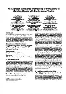
DecisionTree (DT) *DT_ID . optimal_solution
We applied the integrated OOA and model-checking methodology to reengineering of a robotic decision-support software system [10] which testing and maintenance were obstructed by its complexity.
Refer to http://robotics.utexas.edu/rrg/glossary for robotic terms
R12
SimpleSearchSpace(SSS) * SSS_ID . SS_ID (R18) . condition
R18
* SS_ID . SS_size . DT ID (R12)
9
has
Evaluates a trial configuration
Combinational SearchSpace(CSS)
R17
* FSS_ID . SS_ID (R17) . condition
Consists of a number of trial configurations R13
JointConfiguration (JC) *JC_ID . Joint_ID(R7)
. direction
1
has
Search Space (SS)
creates
. status
4.1 Robot Redundancy Resolution Problem1 A software system used for robot redundancy resolution was examined. A robot is considered redundant if it has more independent joints than a number of independent variables specifying position and z orientation of the robot’s x y θ+δ end-effector (which equals to 6). For a redundant robot an infinite number of the robot’s joint displacements can lead to a definite endθ-δ effector position. Figure 2 Initial C o nfiguratio n θ shows a redundant robot T rial C onfiguratio n demonstrating this phenomenon. Failure Figure 2. Plane Geometry recovery is one of the of a Redundant Robot, examples of redundancy Representing a Simple resolution application: if an Exploration Pattern of the actuator fails, the controller Direct Search Technique locks the faulty joint and the redundant robot continues operation. Multiple performance criteria [11] are used to solve a decision-
P erfo rm a n ce M o n i to r i n g
R7
. trial_angle . type . NoinSet . TS_counter . Status
TrialConfiguration (TC) *TC_ID can have different
R6
. configuration . validSolutions . SS_ID(R13) . status . LockConfiguraion . TP_ID(R5) . JC_ID(R6)
Is used for evaluation of a trial configuration
R15
Performance Criterion (PC) * PC ID . average value . status . FC_ID (R16) . scale . PC_name .TC_ID (R15)
R16
R10
OSCAR Interfaces *OS_ID . TC_ID(R10) . status
Specifies initial base point R5
TrajectoryPoint (TP) *TR_ID . point
Figure 4. Object Information Diagram of the Decision Making Component
temporarily changing one or more of the joint displacements in either the positive or negative direction. This project focuses on two different exploration strategies: “simple” and “combinational”. “Simple” exploration describes a strategy of perturbing only one joint displacement at a time. This exploration pattern finds the individual influence of each joint displacement on the arm configuration at any fixed end-effector position. “Combinational” perturbation pattern explores the effect of both individual and simultaneous displacements of redundant joints. Figure 2 demonstrates a “simple” exploration for one of the robot arm joints with θ - being a joint angle and δ - being a displacement. Direct search is a method of solving problems numerically using sets of trial solutions to guide a search. The search begins with an estimate of the solution which
represents an initial arm configuration and serves as an initial base point for the search. Explorations about the base point are generated to produce a set of trial configurations. The second phase of the search is application of performance criteria to the set of candidate solutions. Criteria fusion is used to assure a balance among the criteria. A decision-making process selects one trial configuration as the next base point. Explorations are then performed about this new base point. This process of explorations and decision-making continues until the search finds an acceptable solution. Search Space (SS)
Create CombinationalSS[SEARCH_ TYPE==”combinational”]
Create SimpleSS
Simple SearchSpace (SSS)
Combinational SearchSpace (FSS)
Request Joint Perturbation Request Joint Perturbation
Define JointSearchSpace
Error Recovery
Joint Configuration (JC)
Calculate Trail Configuration [JC satisfies the joint angle limit]
Delete JC [optimal_solution is found] Report status Error Recovery
Decision Tree (DT)
Find optimal solution Report status
Trial Configuration (TC)
Performance EvaluationRequest [ base point is defined]
Adjust Joints [optimal_solution is found]
Calculate Kinematics SearchSpace is built [Number of TC == SS size]
Calculate Performance Criteria
OSCAR Interfaces
Scheduling of concurrently running processes Controlling the direct search algorithm: Internal events External events
Figure 5. Collaboration Diagram of the Decision Making Component
4.2 Rigorous Specifications The robotic decision support system was rigorously specified using the xUML notation. We present the static and dynamic structures of the robotic system, which development followed the efficiency and dependability rules defined in Section 3.
4.2.1 Static Structure. The robot system was designed as a collection of four major functional components: OSCAR Libraries, Kinematics, Performance Monitoring and Decision Making. Each component consists of a number of tightly coupled, cohesive objects. OSCAR Libraries unit defines interfaces to the computational libraries of the existing robotic software, OSCAR [10]. The Kinematics unit captures the robot motion control algorithms. The Performance Monitoring unit specifies the mathematical description of the robot performance criteria, and criteria scaling and fusing algorithms. The Decision Making component formalizes the decision-making algorithms. The conformance to Rule 5 is illustrated in Figure 3. You can see that there are no cyclic dependencies among the system components. The architectural design of the Decision Making component is presented in Figure 4. Conceptual entities of this unit are defined by the following objects: DecisionTree (DT), SearchSpace (SS), SimpleSearchSpace (SSS), CombinationalSearchSpace (CSS), JointConfiguration (JC) and TrialConfiguration (TC). The Decision Making component interfaces the PerformanceCriterion (PC) object of the PerformanceMonitoring unit and the TrajectoryPoint (TP) object of the Kinematics unit (the interfacing relationships are depicted by dashed lines in Figure 4). Semantics of the objects is defined by attributes and relationships. Attributes of the JC object are illustrated below. Each instance of the JC object represents orientation of a joint displaced from its base position. JC_ID is a key attribute whose value uniquely distinguishes each instance of a JC object. Joint_ID is a referential attribute, which represents formalization of the relationship R7 and is used to tie an instance of the JC object to an instance of the Joint object which belongs to the Kinematics unit (if we change the value of Joint_ID from 1 to 2 it means that we are evaluating configuration of the second joint instead of the first one). Trial_angle, NoinSet and TS_counter are descriptive attributes and they provide facts intrinsic to the JC object. For example, trial_angle is used to keep the value of the joint angle that changes during exploration about the base point. Status, type and direction attributes are so called naming attributes which provide facts about the arbitrary labels carried by each instance of an object. The domain of the naming attributes is specified by enumeration of all possible values that the attribute can take on. Status represents status of the object instance, in other words the names of all states of the object’s state machine. Attribute direction domain is {“+delta”,”delta”,”comb+delta”,”comb-delta”}. Attribute Type domain is {“simple”,”combinational”}. The executable model of the Decision Making unit is
defined using a binary type of relationship. An example of one-to-many binary SearchSpace-TrialConfiguration relationship states that a single instance of the SearchSpace object consists of many instances of the TrailConfiguration object. 4.2.2 Dynamic Structure. The Collaboration Diagram SS Redundancy==2 &&SEARCH_TYPE==”combinational”
SSS1
SSS2
J.J_ID==1
JC1
JC3
CSS1
J.J_ID==2
JC2 JC4
CS_counter==1
JC5 J.J_ID==1
direction==”+delta”
CSS2 CS_counter==2
JC6 J.J_ID==2
JC7
JC8
J.J_ID==1 J.J_ID=2
direction==”-delta” direction==”comb+delta”
JC(1).trial_angle