energies Review
Diagnostic Measurements for Power Transformers Stefan Tenbohlen 1, *, Sebastian Coenen 2 , Mohammad Djamali 1 , Andreas Müller 3 , Mohammad Hamed Samimi 1 and Martin Siegel 1 1
2 3
*
Institute of Power Transmission and High Voltage Technology, University of StutFtgart, Stuttgart 70569, Germany;
[email protected] (M.D.);
[email protected] (M.H.S.);
[email protected] (M.S.) General Electric Grid Solutions; Moenchengladbach 41065, Germany;
[email protected] TÜV Süd Energietechnik, Filderstadt 70794, Germany;
[email protected] Correspondence:
[email protected]; Tel.: +49-711-685-67870
Academic Editor: Issouf Fofana Received: 24 February 2016; Accepted: 11 April 2016; Published: 6 May 2016
Abstract: With the increasing age of the primary equipment of the electrical grids there exists also an increasing need to know its internal condition. For this purpose, off- and online diagnostic methods and systems for power transformers have been developed in recent years. Online monitoring is used continuously during operation and offers possibilities to record the relevant stresses which can affect the lifetime. The evaluation of these data offers the possibility of detecting oncoming faults early. In comparison to this, offline methods require disconnecting the transformer from the electrical grid and are used during planned inspections or when the transformer is already failure suspicious. This contribution presents the status and current trends of different diagnostic techniques of power transformers. It provides significant tutorial elements, backed up by case studies, results and some analysis. The broadness and improvements of the presented diagnostic techniques show that the power transformer is not anymore a black box that does not allow a view into its internal condition. Reliable and accurate condition assessment is possible leading to more efficient maintenance strategies. Keywords: power transformer; condition assessment; reliability; failure statistic; partial discharge measurement; frequency response analysis (FRA); dissolved gas analysis (DGA); dielectric response measurement; moisture in oil; dynamic thermal modeling
1. Introduction The reliability of the electrical power system depends on the performance and availability of its components such as power transformers. Due to the increasing age of the transformer population condition assessment and thus onsite diagnostics are important issues to secure a reliable operation of the electrical power system. During the last decades, major works are being carried out for development of reliable and accurate condition assessment techniques [1]. Offline methods require disconnecting the transformer from the power network and are mainly used during scheduled inspections or when the transformer is already failure suspicious. In comparison to this, online methods are used during the operation and offer a possibility to record the condition under realistic operating conditions (e.g., electric field, load, and temperature). Monitoring is the continuous application of online measurement techniques which allows trending and the early detection of an oncoming fault by automatic evaluation of these data. The applicability of the different condition assessment techniques are depicted in Table 1. Localized internal insulation failures can lead to catastrophic breakdown. To reduce such risk, power transformers have to pass a range of factory tests including one for partial discharge (PD) activity before acceptance and commissioning. Onsite PD measurements are often restricted by high site Energies 2016, 9, 347; doi:10.3390/en9050347
www.mdpi.com/journal/energies
Energies 2016, 9, 347
2 of 25
interference. Hence the electrical PD-measurement set-up according to International Electrotechnical Commission (IEC) 60270 [2] usually has sensitivity limitations for onsite/online measurements. In contrast, the sensitivity of unconventional ultra-high frequency (UHF) PD measurements is sufficient and normally not affected by external disturbances. Especially in noisy surroundings, it is a helpful method to support other PD diagnostic techniques for example acoustic localization of PD. Table 1. Status of different condition assessment techniques. DGA: dissolved gas analysis; PD: partial discharge, IEC: International Electrotechnical Commission, UHF: ultra-high frequency, FRA: frequency response analysis, PDC: polarization and depolarization currents, FDS: frequency domain spectroscopy. Method Ageing of oil (e.g., color, moisture, and tan δ) Furan in oil analysis Gas-in-oil analysis (DGA) PD (IEC 60270) Unconventional PD-measurement (e.g., UHF PD measurement) Transfer function (FRA) Dielectric diagnostic (PDC and FDS) Thermal monitoring Degree of polymerization (DP-value)
Offline xxx xX xxx xxx xx xxX xx -
Online xXx XX xXx XX XX X -
Monitoring 1
x xXx X X XX -
Offsite xxx XX xxx XXX XX XXX XX XXX
XXX: generally accepted or standardized; XX: accepted by different users; X: under investigation or consideration; 1 moisture measurement; and -: not applicable.
Frequency response analysis (FRA) compares measured transfer functions of power transformers. Deviations between frequency response curves indicate electrical or mechanical damages of windings. Interpretation of the deviations between transfer functions is not a standardized process and promises to be more reliable and meaningful if skilled knowledge about the transformer design is incorporated. Especially, the established dissolved gas analysis (DGA) can provide relevant information about internal transformer faults. Natural aging, thermal and electrical failures generate typical fault gases, which dissolve in the insulating oil. By analyzing these fault gas profiles, evaluation of kind and severity of the fault can be estimated. Online monitoring of the content of dissolved gases is a powerful tool, enabling the control of fault gas development continuously and thus guaranteeing an optimal energy transmission. Another factor is the assessment of the transformer’s ageing condition. Ageing depends directly on operating temperature and time. The limiting factor of lifetime is the degradation of paper insulation. This goes hand in hand with moisture production from the ageing process. Thus, by knowing the moisture content in the solid insulation, it is possible to get an idea of the ageing condition and decide further actions. Moisture assessment can be done in various ways. For onsite offline measurements, dielectric spectroscopy is a viable tool. Moisture has an effect on the dielectric response of the insulating system. Among different methods frequency domain spectroscopy (FDS) will be presented in detail. The lifetime performance of a power transformer strongly depends on the temperatures its materials have been exposed to. Because of their significant effect, a profound knowledge about these temperatures is of great interest. Due to transient load conditions, changing ambient conditions, adjustable cooling systems and their design and operation principles, transformers represent a rather complex thermal system. In addition, the particular design of a certain transformer, with its applied materials and installed components, complicates precise simulations tremendously. However, knowledge about the exact temperature distribution inside a transformer may not be necessary within the scope of every desired application. For instance, the determination of a constant, non-critical level of overload might already be achieved by means of a simplified thermal model which additionally can offer the possibility of monitoring of the operational state of the cooling unit.
Energies 2016, 9, 347
3 of 25
2. Failure Statistic of Power Transformers Accurate information about service experience of high voltage (HV) equipment is of great Energies 2016, 9, 347 3 of 25 importance for both manufacturers and utilities of such equipment. It helps the manufacturers to improve their products, andTransformers provides important inputs for the utilities when buying equipment, 2. Failure Statistic of Power organizing maintenance and benchmarking their performance. Statistical analysis of past failure Accurate information about service experience of high voltage (HV) equipment is of great data can show useful features with respect to future failure behavior. Equipment reliability data importance for both manufacturers and utilities of such equipment. It helps the manufacturers to are also required when assessing the overall reliability of an electric power system. Furthermore, improve their products, and provides important inputs for the utilities when buying equipment, international standards applicable to HV equipment are being improved on of service experience organizing maintenance and benchmarking their performance. Statisticalbased analysis past failure and reliability data. data can show useful features with respect to future failure behavior. Equipment reliability data are International of large electric systems (CIGRE) working therefore developed also required council when assessing the overall reliability of an electric group powerA2.37 system. Furthermore, internationaltostandards applicable HV equipment aretransformers being improved based on service a questionnaire collect utility failuretostatistics for power in a standardized way [3]. experience and reliability data. Besides information about the population under investigation, failure data were collected for various electriclocations, systems failure (CIGRE) working group A2.37 therefore groups ofInternational transformerscouncil in termsofoflarge the failure causes, failure modes, actions, external developed a questionnaire to collect utility failure statistics for power transformers in a standardized effects and others parameters. way [3]. Besides information about the population under investigation, failure data were collected A major failure was defined as any situation that required the transformer to be removed for various groups of transformers in terms of the failure locations, failure causes, failure modes, from actions, serviceexternal for a period longer than seven days for investigation, remedial work or replacement. effects and others parameters. The necessary repairs should have involved majorthat remedial work, usually requiring the transformer A major failure was defined as any situation required the transformer to be removed from to be service removed its installation site and returned to the factory. A major would require at for from a period longer than seven days for investigation, remedial work failure or replacement. The least the opening of the transformer or the tap changer tank, or an exchange of the A reliable necessary repairs should have involved major remedial work, usually requiring thebushings. transformer to be removed from its installation site andprevents returned its to the A major failure would require at indication that the transformer condition safefactory. operation is considered a major failure, if least the opening of the transformer or the tap changer tank, or an exchange of the bushings. A remedial work (longer than seven days) was required for restoring it to the initial service capability. reliable indication transformer its safe operation is considered a major In some cases, failures that werethe also assigned condition as major, prevents if remedial work was shorter than seven days and failure, if remedial work (longer than seven days) was required for restoring it to the initial service extensive work with oil processing had to be done (e.g., exchange of bushings). capability. In some cases, failures were also assigned as major, if remedial work was shorter than The working group collected 964 major failures which occurred in the period 1996–2010, within seven days and extensive work with oil processing had to be done (e.g., exchange of bushings). a total population of 167,459 transformer-years, contributed by 58 utilities from 21 countries [3]. The The working group collected 964 major failures which occurred in the period 1996–2010, within year of manufacture unitstransformer-years, span from the 1950s up to 2009 the reference periods[3]. range a total populationofofthe 167,459 contributed by 58and utilities from 21 countries The from 3 years to 11 years. Because the number of operational transformers was only provided for one year of manufacture of the units span from the 1950s up to 2009 and the reference periods range year, the total of11 transformer-years (population per utility) was calculated under the assumption fromnumber 3 years to years. Because the number of operational transformers was only provided for one year, the total number of transformer-years per utility) was calculated under the of that the number of transformers in operation was(population constant during the reference period. The number assumption that the number of transformers inthe operation wasperiod constantinduring reference transformers was multiplied with the length of reference years the to obtain anperiod. estimate of The number number of was multiplied length of the reference period in years to(1): obtain the total oftransformers transformer-years. Failurewith ratethe was calculated according to Equation an estimate of the total number of transformer-years. Failure rate was calculated according to Equation (1): n1 ` n2 ` . . . ` n i
λ“
pN1 ` N . ....` N n12` n2. ni i q ˆ T λ
( N1 N 2 ... Ni ) T
ˆ 100%
100%
(1)
(1)
where ni = number of failures in i-th year; Ni = number of transformers operating in the i-th year; and where ni =period number of failuresone in i-th year; Ni = number of transformers operating in the i-th year; and T = reference (normally year) T = reference period (normally one year) The overall failure rate of substation and generator step-up units were all within 1% (Table 2). The overall failure rate of substation and generator step-up units were all within 1% (Table 2). The failure data of the full population were analyzed as a function of the primary location (component) The failure data of the full population were analyzed as a function of the primary location in the transformer where the failure was initiated. Figure 1 shows the failure location analysis for (component) in the transformer where the failure was initiated. Figure 1 shows the failure location substation transformers with voltages 100 kV and above, respectively. analysis for substation transformers with voltages 100 kV and above, respectively.
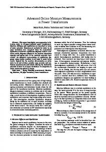
Figure 1. Failure locations of substation transformers (>100 kV) (based on 536 major failures) [4].
Figure 1. Failure locations of substation transformers (>100 kV) (based on 536 major failures) [4].
Energies 347 Energies 2016, 2016, 9, 9, 347
4 of 25
Table 2. Investigated population and failure rates of substation transformers [4]. Table 2. Investigated population and failure rates of substation transformers [4]. Population information Population Number of information transformers Number of Transformer transformers years Transformer years Major Major failures failures Failure rate Failure rate
69 ≤ kV < 100
100 ≤ kV < 200
69 ď2962 kV < 100
100 ď10,932 kV < 200
2962
10,932
15,267
64,718
144 144
280 280
0.94%
0.43%
15,267
0.94%
64,718
0.43%
Highest system voltage (kV) 200 ≤Highest kV < 300 300voltage ≤ kV