WEIDMANN
Transformer Seminar 2015
‘Large’ Shell-Type Power Transformers New Perspectives Through Advanced Thermal Modelling Techniques
Hugo M. R. Campelo, R&D Project Manager – Thermal and Fluids,
[email protected]
Prepared by EFACEC Energia, Transformers R&D, Portugal for presentation in Pfäffikon, Switzerland, April 2015
WEIDMANN
Transformer Seminar 2015
Motivation Shell Type Construction Shell-Type Transformers
Quick and Basic Overview
EFACEC Vision and Strategy New Perpectives – Thermal Performance
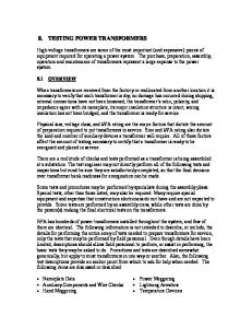
EFACEC biggest SHELL transformer, 900 MVA, Rincon Plant, Georgia, USA, 2013
Types of Cooling Channels Flow Rate Inlet Flow Distribution Flow Distribution Between the Coils Spacer Distribution Number of Inlets/Outlets
Innovative Activities Proprietary THNM for Shell Transformers Experimental Validations
Summary 2
Prepared by EFACEC Energia, Transformers R&D, Portugal for presentation in Pfäffikon, Switzerland, April 2015
WEIDMANN
Transformer Seminar 2015
Most of the transformers worldwide are CORE-Type. CORE-Type is a much more disseminated technology. More manufacturers. The available information on Shell-Type is scarce. Hence the public perception on the real cooling mechanisms acting on these machines is lower.
A significant contribution to the community is being conducted under the patronage of Cigré Working Group A2.38. A special chapter on this brochure is being dedicated to this particular technology.
EFACEC manufactures both large Core-Type and large Shell-Type Transformers up to 500kV. Its position is then priviliged. 3
Prepared by EFACEC Energia, Transformers R&D, Portugal for presentation in Pfäffikon, Switzerland, April 2015
WEIDMANN
Transformer Seminar 2015
Each winding comprises a variable number of pancake coils (rectangular shaped) Pressboard spacers that simultaneously guide the oil and help widhstanding forces 4
Prepared by EFACEC Energia, Transformers R&D, Portugal for presentation in Pfäffikon, Switzerland, April 2015
WEIDMANN
Transformer Seminar 2015
Quite similar geometric configurations between the different hydraulic circuits Different configurations are generated by adding or removing similar circuits Geometry of tank together with magnetic circuit shape guarantees oil is always directed – OD vs OF?
5
Prepared by EFACEC Energia, Transformers R&D, Portugal for presentation in Pfäffikon, Switzerland, April 2015
WEIDMANN Transformer Seminar 2015
6
Prepared by EFACEC Energia, Transformers R&D, Portugal for presentation in Pfäffikon, Switzerland, April 2015
WEIDMANN Transformer Seminar 2015
7
Prepared by EFACEC Energia, Transformers R&D, Portugal for presentation in Pfäffikon, Switzerland, April 2015
WEIDMANN Transformer Seminar 2015
8
Prepared by EFACEC Energia, Transformers R&D, Portugal for presentation in Pfäffikon, Switzerland, April 2015
WEIDMANN Transformer Seminar 2015
9
Prepared by EFACEC Energia, Transformers R&D, Portugal for presentation in Pfäffikon, Switzerland, April 2015
WEIDMANN Transformer Seminar 2015
10
Prepared by EFACEC Energia, Transformers R&D, Portugal for presentation in Pfäffikon, Switzerland, April 2015
WEIDMANN Transformer Seminar 2015
11
Prepared by EFACEC Energia, Transformers R&D, Portugal for presentation in Pfäffikon, Switzerland, April 2015
WEIDMANN Transformer Seminar 2015
12
Prepared by EFACEC Energia, Transformers R&D, Portugal for presentation in Pfäffikon, Switzerland, April 2015
WEIDMANN Transformer Seminar 2015
13
Prepared by EFACEC Energia, Transformers R&D, Portugal for presentation in Pfäffikon, Switzerland, April 2015
WEIDMANN Transformer Seminar 2015
14
Prepared by EFACEC Energia, Transformers R&D, Portugal for presentation in Pfäffikon, Switzerland, April 2015
WEIDMANN Transformer Seminar 2015
15
Prepared by EFACEC Energia, Transformers R&D, Portugal for presentation in Pfäffikon, Switzerland, April 2015
WEIDMANN
Transformer Seminar 2015
widely used in the US; ~100% of the nuclear fleet in Belgium; ~50% of the nuclear fleet in France; ~85% of the 400kV network in Spain.
16
Prepared by EFACEC Energia, Transformers R&D, Portugal for presentation in Pfäffikon, Switzerland, April 2015
WEIDMANN
Transformer Seminar 2015
Efficiency Smarter Design (…and Operation) High Order Models (Commercial)
Reduced Order Models (Proprietary)
Numerical Simulations
Algebraic models Experiments Real Transformers Other Experiments
17
Transformer Seminar 2015
High Order Models Computational Fluid Dynamics
Reduced Order Models THNMs Thermal-Hydraulic Network Analysis
Transformer Geometry
Experiments Validation Real Transformers
Mesh
Processor
Link
Prepared by EFACEC Energia, Transformers R&D, Portugal for presentation in Pfäffikon, Switzerland, April 2015
WEIDMANN
Post-Process (a) Thermal Data (b) Hydraulic Data
Statistics
T field V field
Scaled-Down Apparatus
End
18
Prepared by EFACEC Energia, Transformers R&D, Portugal for presentation in Pfäffikon, Switzerland, April 2015
WEIDMANN
Transformer Seminar 2015
High-Order Models (CFD) Discretization of Navier-Stokes equations. Meaning more detail, hence more capabilities.
Resource intensive – demand for specific data as input, computational infrastructure, specific skills…. The ‘transformer designer’ does not need such amount and type of information.
Reduced-Order Models (THNMs) Algebraic sets of simplified equations. Highly flexible and faster time-to-solution. Can be tuned and more easily adapted to new geometries. More easily combinated with other existing models. No licensing costs. No dependence on versions. Some important flow characteristics cannot be modelled. The solution depends on fitting expressions.
Neither is perfect. But the combination of both is almost….
Prepared by EFACEC Energia, Transformers R&D, Portugal for presentation in Pfäffikon, Switzerland, April 2015
WEIDMANN
Transformer Seminar 2015
CFD (Computational Fluid Dynamics) and
THNMs (Thermal-Hydraulic Network Models) represent the most advanced thermal modelling techniques
these techniques enable unprecedented comprehension capabilities
20
Transformer Seminar 2015
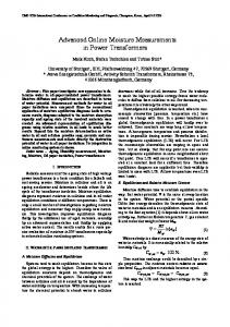
100 95 90
85 80 fRe
Prepared by EFACEC Energia, Transformers R&D, Portugal for presentation in Pfäffikon, Switzerland, April 2015
WEIDMANN
75 70 65 Transverse-450W Transverse-1000W Radial-450W Radial-1000W R. K. Shah & A. L. London Parallel Plates Limit
60 55
50 0
2
4
6 8 Aspect Ratio
10
12
Results are originally extracted from H.M.R. Campelo et al., “Extracting Relevant Transport Properties Using 3D CFD Simulations of Shell-Type Electric Transformers”, ICHMT International Symposium on Advances in Computational Heat Transfer, NJ, USA, May 2015 (to be published) 21
Prepared by EFACEC Energia, Transformers R&D, Portugal for presentation in Pfäffikon, Switzerland, April 2015
WEIDMANN
Transformer Seminar 2015
Zig-Zag typical flow pattern
Recirculation areas
Oil Velocity Vectors
Results are originally extracted from P. J. Gomes et al., “Large Power Transformer Cooling – Flow Simulation and PIV analysis in an Experimental Prototype”, Advanced Research Workshop on Transformers, Baiona, Spain, 2007. 22
Prepared by EFACEC Energia, Transformers R&D, Portugal for presentation in Pfäffikon, Switzerland, April 2015
WEIDMANN
Transformer Seminar 2015 Scale Minimum = 0 cm/s Scale Maximum = 3𝑣𝐺
0.25Q
2Q
Results are originally extracted from H.M.R. Campelo et al., “Extracting Relevant Transport Properties Using 3D CFD Simulations of Shell-Type Electric Transformers”, ICHMT International Symposium on Advances in Computational Heat Transfer, NJ, USA, May 2015 (to be published) 23
Transformer Seminar 2015 15%
Mass Flow Rate [%]
Prepared by EFACEC Energia, Transformers R&D, Portugal for presentation in Pfäffikon, Switzerland, April 2015
WEIDMANN
12%
9% 0.25Q
6%
2Q
3%
0% 1
2
3
4
5
6
7
8
9
10
11
Channel ID
0.25Q
2Q
Results are originally extracted from H.M.R. Campelo et al., “Extracting Relevant Transport Properties Using 3D CFD Simulations of Shell-Type Electric Transformers”, ICHMT International Symposium on Advances in Computational Heat Transfer, NJ, USA, May 2015 (to be published) 24
Transformer Seminar 2015 Scale Minimum = 𝑇𝑖𝑛𝑙𝑒𝑡 Scale Maximum = 2 ∗ 𝑇𝑜𝑢𝑡𝑙𝑒𝑡
1.0
0.25Q0.8
24-4 Channel Vertical Position
Prepared by EFACEC Energia, Transformers R&D, Portugal for presentation in Pfäffikon, Switzerland, April 2015
WEIDMANN
(Toil , z ,i Tinlet ) (T massweighted ,outlet Tinlet )
0.25Q 0.5Q Q 1.33Q 2Q
0.6
0.4
2Q0.2
0.0 0.0
0.2
0.4
0.6
0.8
1.0
Dimensionless Oil Temperature Results are originally extracted from H.M.R. Campelo et al., “Extracting Relevant Transport Properties Using 3D CFD Simulations of Shell-Type Electric Transformers”, ICHMT International Symposium on Advances in 25 Computational Heat Transfer, NJ, USA, May 2015 (to be published)
Transformer Seminar 2015
120
120 MAX-1.95H-450W MAX-1.46H-450W MAX-1.33H-450W AVG-1.95H-450W AVG-1.46H-450W AVG-1.33H-450W
MAX-1.95H-450W MAX-1.46H-450W MAX-1.33H-450W
110
110
AVG-1.95H-450W Hot Plate Temperature [°C]
AVG-1.46H-450W Oil Temperature [°C]
Prepared by EFACEC Energia, Transformers R&D, Portugal for presentation in Pfäffikon, Switzerland, April 2015
WEIDMANN
AVG-1.33H-450W
100
90
80
100
90
80
70
70
60
60
0.25Q
0.5Q
Q Flow Rate
1.38Q
2Q
0.25Q
0.5Q
Q
1.38Q
2Q
Flow Rate
Results are originally extracted from H.M.R. Campelo et al., “Extracting Relevant Transport Properties Using 3D CFD Simulations of Shell-Type Electric Transformers”, ICHMT International Symposium on Advances in 26 Computational Heat Transfer, NJ, USA, May 2015 (to be published)
Transformer Seminar 2015
Pressure BC = 0.33Q - Mass Flux BC = 0.25Q 1.0
1.0 0.9
Using Pressure BC
0.9
Using Pressure BC
0.8
Using Mass Flux BC
0.8
Using Mass Flux BC
Y Inlet Position
Inlet
0.6 0.5
0.4
y
0.3
Inlet
0.7
0.7
Y Inlet Position
Prepared by EFACEC Energia, Transformers R&D, Portugal for presentation in Pfäffikon, Switzerland, April 2015
WEIDMANN
0.6 0.5
0.4
y
0.3
x
0.2
x
0.2
0.1
0.1
0.0 0.95
0.0 0.96
0.98 0.97 Dimensionless Pressure
0.99
1.00
0.0
0.2
0.6 0.4 Dimensionless Velocity
0.8
1.0
Inlet Profile Not Affected by Imposed Flow Rate. Dependent on pure geometrical aspects. Crucial difference comparing with Core-Type. Results are originally extracted from R.T. Oliveira, MSc. Thesis, “Modelling and Simulation of Flow and Heat Transfer in Shell-Type Power Transformers”, Chemical Engineering Department, University of Porto and EFACEC R&D, 2014. 27
Transformer Seminar 2015 Pressure BC = 0.33Q
1.0
1.0
0.9
0.9
0.8
1.33H
1.33H
0.8
1.95H
1.95H
Y Inlet Position
Inlet
0.6 0.5 0.4
y
0.3
Inlet
0.7
0.7 Y Inlet Position
Prepared by EFACEC Energia, Transformers R&D, Portugal for presentation in Pfäffikon, Switzerland, April 2015
WEIDMANN
0.6 0.5
0.4
y
0.3
x
x
0.2
0.2
0.1
0.1
0.0 0.95
0.96
0.97 0.98 Dimensionless Pressure
0.99
1.00
0.0 0.00
0.20
0.40 0.60 Dimensionless Velocity
0.80
1.00
Inlet Profile Not Affected by Washer Height. Crucial difference comparing with Core-Type. Results are originally extracted from R.T. Oliveira, MSc. Thesis, “Modelling and Simulation of Flow and Heat Transfer in Shell-Type Power Transformers”, Chemical Engineering Department, University of Porto and EFACEC R&D, 2014. 28
Prepared by EFACEC Energia, Transformers R&D, Portugal for presentation in Pfäffikon, Switzerland, April 2015
WEIDMANN P
P
48 L A Q Dh2
48 L A v Dh2 A
Transformer Seminar 2015
P RH Q
P
RH v A
The flow distribution between the coils is linear. This simplifies the modelling approaches. More controllable technology. Results partially reproduced from Cigré WGA2.38 brochure to be pubished (expectably in 2015). The plots herein presented belong to JST Transformers. The plots are herein used for the sole purpose of demonstarting how the oil flow is typically distributed between the different coils of a shell-type transformer. More information on the coming brochure. 29
Prepared by EFACEC Energia, Transformers R&D, Portugal for presentation in Pfäffikon, Switzerland, April 2015
WEIDMANN
Transformer Seminar 2015
Optimization and control of pressboard spacer distribution. Results are originally extracted from P. J. Gomes et al., “Large Power Transformer Cooling – Flow Simulation and PIV analysis in an Experimental Prototype”, Advanced Research Workshop on Transformers, Baiona, Spain, 2007. 30
Prepared by EFACEC Energia, Transformers R&D, Portugal for presentation in Pfäffikon, Switzerland, April 2015
WEIDMANN Original
Transformer Seminar 2015
Optimized Original
Optimized
Oil Flow Area (%)
64
63
Thickness (mm)
5
5
Non-Supported Copper Distance (mm)
90
60
Even with an optimized flow distribution, the corresponding impact on temperatures is weak. Another crucial difference comparing with Core-Type.
31
Prepared by EFACEC Energia, Transformers R&D, Portugal for presentation in Pfäffikon, Switzerland, April 2015
WEIDMANN
Transformer Seminar 2015
In Shell-Type typical configurations the areas near the inlets and the outlets are typically more stagnant due to the curvature of the pancake geometry.
That effect is typically controlable by moddifying the number of inlets/outlets.
32
Prepared by EFACEC Energia, Transformers R&D, Portugal for presentation in Pfäffikon, Switzerland, April 2015
WEIDMANN 13 INlets
Transformer Seminar 2015 7 INlets
33
Prepared by EFACEC Energia, Transformers R&D, Portugal for presentation in Pfäffikon, Switzerland, April 2015
WEIDMANN
13 OUTlets
Transformer Seminar 2015
7 OUTlets
34
Prepared by EFACEC Energia, Transformers R&D, Portugal for presentation in Pfäffikon, Switzerland, April 2015
WEIDMANN
Transformer Seminar 2015
13 INlets /13 OUTlets B Curved Zone 1 G Curved Zone 2 A
7 INlets / 7 OUTlets
Taverage (%)
Tmaximum (%)
44.3 42.5 43.4 43.8 47.5
90.0 93.6 98.6 84.9 84.5
B Curva 1 G Curva 2 A
Taverage (%)
Tmaximum (%)
42.9 42.5 43.8 43.8 45.7
90.0 95.4 100 84.0 84.0
35
Prepared by EFACEC Energia, Transformers R&D, Portugal for presentation in Pfäffikon, Switzerland, April 2015
WEIDMANN
Transformer Seminar 2015
13 inlets
7 inlets
Taverage (%)
43.8
43.8
Tmaximum (%)
98.6
100
The stagnant oil zones are easily manageable with simple design decisions. Their impact on the solid temperatures are reduced by the high thermal conductivity of the copper. 36
Prepared by EFACEC Energia, Transformers R&D, Portugal for presentation in Pfäffikon, Switzerland, April 2015
WEIDMANN
Transformer Seminar 2015
An innovative THNM approach has been developed for Shell-Type Transformers. 37
Prepared by EFACEC Energia, Transformers R&D, Portugal for presentation in Pfäffikon, Switzerland, April 2015
WEIDMANN
Transformer Seminar 2015
Typical Outputs from the THNM
Cooling Fluid Velocity Field
Solid Temperature Field
38
Transformer Seminar 2015
20
20
FluSHELL-Base Q FluSHELL-Base Q/10 FluSHELL-i1 Q FluSHELL-i1 Q/10
Temperature Difference FluSHELL-CFD [°C]
Temperature Difference FluSHELL-CFD [°C]
Prepared by EFACEC Energia, Transformers R&D, Portugal for presentation in Pfäffikon, Switzerland, April 2015
WEIDMANN
15
10
5
0
FluSHELL-Base Q FluSHELL-Base Q/10 FluSHELL-i1 Q FluSHELL-i1 Q/10
15
10
5
0
20
24
28
28s
24s
Line ID
Solid temperatures
20s
20
24
28 28s Line ID
24s
Fluid temperatures
20s
39
Prepared by EFACEC Energia, Transformers R&D, Portugal for presentation in Pfäffikon, Switzerland, April 2015
WEIDMANN
Transformer Seminar 2015
Measured
ANSYS Fluent®
Results are originally extracted from P. J. Gomes et al., “Large Power Transformer Cooling – Flow Simulation and PIV analysis in an Experimental Prototype”, Advanced Research Workshop on Transformers, Spain, 2007. 40
Prepared by EFACEC Energia, Transformers R&D, Portugal for presentation in Pfäffikon, Switzerland, April 2015
WEIDMANN
Transformer Seminar 2015
A scaled down model of a Shell-Type winding has been built in EFACEC in order to validate the THNM. 41
Prepared by EFACEC Energia, Transformers R&D, Portugal for presentation in Pfäffikon, Switzerland, April 2015
WEIDMANN
Transformer Seminar 2015
The lack of public information about Shell-Type can conduct to a lower degree of confidence. The cooling mechanisms acting in Shell-Type transformers can be highly controllable (optimized spacer distribution, number of inlets…). The flow distribution in Shell-Type is more dependent on geometrical aspects, enabling more simplified modelling approaches. The current IEC recommendations about H factors are more appropriate for Core-Type reality. Further knowledge dissemination is needed. The flow distribution between the coils is more linear and less dependent on the inertia of the flow. This is a crucial difference to Core-Type. Shell-Type Transformers can be also designed with low hot-spot factors. EFACEC has developed an innovative THNM approach for Shell-type Transformers. A proven record on these techniques is being built, for both transformer technologies, over the last 10 years. EFACEC has also been developing proper scale models to progressively validate present and future thermal modelling approaches. 42
Prepared by EFACEC Energia, Transformers R&D, Portugal for presentation in Pfäffikon, Switzerland, April 2015
WEIDMANN
Transformer Seminar 2015
Part of the reproduced results have been co-funded by Fundação de Ciência e Tecnologia (FCT) and FEDER under Programe COMPETE (Project PEstC/EQB/LA0020/2013) and also by QREN (Project SHELL-CTC), ON2 and FEDER. The presenter would like to make a special mention to EFACEC Shell-Type design departments in Porto Plant, Portugal for their valuable participation and belief during this work. A last, but not the least, a special mention to Cigré Working Group A2.38 and to all those colleagues who jointly contributed with useful information about this technology for all the transformers community.
43
WEIDMANN
Transformer Seminar 2015
Thanks for your attention. Questions?
EFACEC Energia S.A. Power Transformer Manufacturer Porto, Portugal
44