y Presently with Design Technology Center, Hewlett-Packard Co., Palo. Alto, CA. ... sented a simulation-based diagnostic test generation algo- rithm for large sequential .... us call this faulty machine the target machine. Internally, only the base ...
DIAGNOSTIC TEST PATTERN GENERATION FOR SEQUENTIAL CIRCUITS Ismed Hartantoy , Vamsi Boppana, Janak H. Patel Coordinated Science Laboratory University of Illinois Urbana, IL 61801
Abstract A method to perform diagnostic test generation in sequential circuits by modifying a conventional test generator is presented. The method utilizes circuit netlist modification along with a forced value at a primary input in the modified circuit. Techniques to reduce the computational effort for diagnostic test pattern generation in sequential circuits are also presented. Speed-up of the diagnostic ATPG process is achieved by the identification of states that are impossible to justify with three-valued logic.
1 Introduction The aim of fault location or diagnosis is to locate device failures. Diagnosis of VLSI circuits may be intended for the identification and replacement of a faulty sub-circuit or may be performed with a view to improving the manufacturing process. To perform an efficient diagnosis, a test set with good diagnostic capability is needed. Therefore, diagnostic ATPG is a critical part of fault diagnosis. In diagnostic test generation, the goal is to find a test sequence such that the circuit produces a different response under one fault than it does under another. The problem of diagnostic test generation is much harder than conventional test generation, since it has to deal with pairs of faults. The diagnostic test generation problem for sequential circuits is more acute than its combinational circuit counterpart, mainly because of multiple time-frames that need to be handled. The problem is compounded by the unknown values in state elements; these unknown values increase the number of fault pairs that need to be considered by a diagnostic test generator. Therefore, diagnostic test pattern generaThis research was supported in part by the Semiconductor Research Corporation (SRC) under grant 95-DP-109, by the Office of Naval Research (ONR) under grant N00014-95-1-1049, by the Defense Advanced Research Projects Agency (DARPA) under contract DABT63-96-C-0069, and by an equipment grant from Hewlett-Packard. Any opinions, findings and conclusions or recommendations expressed in this material are those of the authors and do not necessarily reflect the views of DARPA. y Presently with Design Technology Center, Hewlett-Packard Co., Palo Alto, CA.
W. Kent Fuchs School of Electrical and Computer Engineering Purdue University West Lafayette, IN 47907-1285
tion for sequential circuits remains a difficult and unsolved problem. Previous research on diagnostic test generation has primarily focused on combinational circuits [6, 7, 11, 13, 25]. Formal techniques have also been used for sequential circuit diagnostic test generation [4, 15]; however, the drawbacks of these approaches are the assumption of a fault-free reset state and the inability to handle large circuits due to memory requirement problems. Recent work [5] has presented a simulation-based diagnostic test generation algorithm for large sequential circuits, but there is a lack of indistinguishability identification. A method to modify a conventional test generator into a diagnostic test generator is presented in Section 3. The method utilizes circuit netlist modification along with a forced 0/1 or 1/0 [24] value at a primary input in the modified circuit. With this modification technique, any test generator can be converted into a diagnostic test generator. If the original test generator has the capability to force a 0/1 or 1/0 value at any primary input, then no source code modification is needed; the modification of the circuit netlist is sufficient to convert the test generator into a diagnostic test generator. Previous work [4, 11, 13, 15] also indicates that the main burden of diagnostic test generation is in proving indistinguishability. It has been mentioned [4] that detectionoriented test sets usually have good diagnostic capability. From our experiments, Table 1 in Section 6 shows that a detection-oriented test set leaves too many undistinguished fault pairs for the diagnostic test generator to handle. To overcome this problem, several heuristics are introduced to identify sequentially indistinguishable fault pairs. First, a theorem that links initializability of the good circuit with the undetectability and distinguishability of two faulty circuits is presented. Next, a technique to rapidly identify states that are impossible to justify with three-valued logic [1] is presented. This rapid identification is achieved by performing test generation on certain transformed circuits to identify state elements (flip-flops) that are not settable by the test generator to specific logic values. This technique is
useful in reducing the time to perform diagnostic test generation. To demonstrate the efficiency of the techniques presented in this paper, HITEC [18] is converted into a diagnostic test generator, DIAGGEN. Results of DIAGGEN are presented in Section 6.
2 Sequential Machine Indistinguishability There are three known different test strategies for sequential circuits: the multiple observation time test strategy [21–23], the single observation time strategy [21–23], and the traditional gate level test generation strategy (using three-valued logic) [2]. Since our technique is implemented in tools that use the traditional three-valued logic, this particular test strategy is used throughout this paper. The following are formal definitions for distinguishability and indistinguishability in sequential circuits with three-valued logic [2]. Definition 1 (Distinguishability) A fault pair (f1, f2) is said to be distinguishable if there exists an input sequence Y such that the output responses produced by the two faulty machines, when starting from the completely unspecified state (i.e., with all Xs, representing the entire state space) and as determined by three-valued logic simulation, are different on a specific time unit and on a specific primary output (i.e., 0 in one machine and 1 in the other or vice versa). Definition 2 (Indistinguishability) A fault pair (f1, f2) is said to be indistinguishable if it is not distinguishable.
3 Diagnostic Test Pattern Generation
f1
3.1
�
PO
f2
1
f1
)+(P O2
�
PO
f2
2
f1 )+ : : : +(P Op
�
PI 1 PI 2
PIq
1001 0101 0101 1100 1100
00111100
00111100
f1 1
f1
PI 1
PO
f1
PI 2
1001 0101 0101 f1 PI
f1 f1 PO 2
M
PO
q
f2
PO
f2
1001 0101 0101 f2 PI q
p
11000011 00110011 00110011
f2 1
PI1
PI 2
11000011 00110011 00110011 f1
M
f2 f2 PO 2
11000011 00110011 00110011 f2 PO p
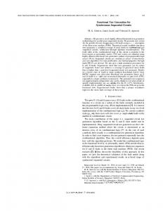
Figure 1: Diagnostic Test Generation using XOR Gates
The diagnostic test generation problem can be viewed as a test generation problem, but with slightly different objectives. The objective of test pattern generation is to generate a test sequence that distinguishes the good machine and a faulty machine, while the objective of diagnostic test pattern generation is to generate a sequence that will distinguish two faulty machines. Suppose there is a sequential machine M with p primary outputs P O1 ; P O2 ; : : : ; P Op ; M f 1 is the sequential machine M that contains fault f 1 and has primary outputs P O1f 1 ; P O2f 1 ; : : : ; P Opf 1 . Similarly the machine f 2 and has primary outputs M that contains fault f 2 is M f2 f2 f 2 P O1 ; P O2 ; : : : ; P Op . The objective of diagnostic test pattern generation is to generate a test sequence that makes the following Boolean function evaluate to a value of 1 at some particular time frame t. (P O1
of the circuit netlist are generated; the first copy implements M f 1 and the second copy implements M f 2 . First, the corresponding primary inputs of the two netlists are tied together so that the number of primary inputs in the new netlist is the same as the number of primary inputs in the original netlist. Next, the corresponding primary outputs from each circuit are XORed and the outputs of the XOR gates are fed into an OR gate. A test generator can then be used to test the satisfiability of the value 1 on the primary output of this new circuit. Figure 1 shows the implementation of a diagnostic test generator using this XOR gates approach.
f 2)
P Op
Diagnostic Test Generator using XOR Gates
Let us first describe a straightforward approach to generate a test sequence that distinguishes M f 1 from M f 2 . The idea is to implement the above Boolean function with circuit netlists as shown in Figure 1. Two different copies
The drawback of the XOR gates approach is that the size of the circuit is doubled and global reconvergences are introduced; hence, it increases the complexity of the test generation task. The advantage of the approach is that no modification is needed in the source code of the test generator; the creation of the two faulty circuits M f 1 and M f 2 connected through XOR gates is enough to generate a test sequence that distinguishes M f 1 from M f 2 .
3.2 Diagnostic Test Generator through Efficient Netlist Modification Conventional test generators use the good machine as the base machine, and target a single fault for detection; let us call this faulty machine the target machine. Internally, only the base machine description is kept. The test generator carries two logic values per node; one value for the base machine and the other value for the target (faulty) machine. The value pair is typically written as base value / target value. The task of a test generator is to generate a test sequence that will distinguish the base machine from the target machine. We view the diagnostic test generation prob-
111 000
target fault Machine: M
f1
PASS I
f1 (s-a-1) A B C
value in base machine
f1 (s-a-1) A B
Base M f2 f1 Target M
0/1
D
value in base machine
A
f2
new input
B
value in target machine
C
D
target fault
1/0 A
f2 (s-a-0)
D
C
new input
Machine: M
value in target machine
PASS II f1 Base M f2 Target M
B
f2 (s-a-0) C
D
Figure 2: Diagnostic Test Generation through Netlist Modification
lem as a test generation problem and consider the base machine as M f 1 and the target machine as M f 2 or vice versa. In order to use a conventional test generator for diagnostic test generation, the circuit netlist is modified such that the base machine is M f 1 and the target machine is M f 2 or vice versa. The modification as illustrated in Figure 2 is done by cutting the line where the fault is located and replacing the line with a two-input OR gate (for stuck-at-1 fault) or a twoinput AND gate (for stuck-at-0 fault); the other input of the added gate is made into a new primary input. A 0/1 or 1/0 value is then assigned to this new primary input. After the netlist modification is done and the new primary input has been assigned a value of 0/1 or 1/0, a conventional test generator can be run to detect the target fault in the new modified netlist. As an example, Figure 2 shows the netlist modification used to generate a sequence that distinguishes f 1 (f1 is a stuck-at-1 fault on line A-B) from M f 2 (f2 M is a stuck-at-0 fault on line C-D). When the base machine is M f 2 , the value 0/1 is assigned to the new input; by this assignment, the output of the added AND gate will always be 0 in the base machine (M f 2 ), representing the stuck-at0 fault on line C-D. Because the second value assigned to this new input is 1, in the target machine the stuck-at-0 fault on line C-D is bypassed. As shown in Figure 2, two passes may be needed for distinguishing the faulty machines corresponding to faults f1 and f2. In the first pass, an attempt is made to excite and propagate a 0/1 or 1/0 from the location of f1 using M f 2
as the base machine and M f 1 as the target machine. If the first pass fails to generate a test sequence that distinguishes f 2 from M f 1 , then the excitation and propagation of a M 0/1 or 1/0 from the location of f2 is attempted; in this second pass, M f 1 is used as the base machine and M f 2 is used as the target machine. Note that the value assigned to one of the inputs of the added gate (the new primary input) should be 0/1 or 1/0. For example, in the first pass in Figure 2, if a value 0/0 is assigned to the new primary input then instead of distinguishing M f 1 from M f 2 , the generated test sequence will distinguish M f 1 from M f 1f 2 (the machine M with the presence of multiple faults f 1 and f 2). In this particular example, the value 0/1 at the new primary input injects fault f 2 ) and at the same time ref 2 into the base machine (M moves the effect of fault f 2 from the target machine (M f 1 ); hence, the generated test sequence will distinguish M f 1 from M f 2 . To declare that M f 1 is indistinguishable from M f 2 , in pass one, the target fault (f 1) has to be declared untestable and in pass two, the target fault (f 2) also has to be declared untestable. This two-pass algorithm is needed because either faulty location might serve as the starting excitation point of a test sequence that distinguishes the two faulty circuits. The advantage of this netlist modification technique is that the complexity of the test generator is not significantly altered, since the size and structure of the circuit are maintained. Furthermore, no source code modification is needed
if the original test generator has the capability of forcing a 0/1 or 1/0 on a primary input.
4 Reducing the Problem Size of Diagnostic Test Generation We have just described a technique for performing diagnostic test generation. However, because the number of fault pairs that needs to be considered during diagnostic ATPG is very large, it is still an expensive process. In this section, we simplify the problem by developing a result that significantly reduces the number of pairs that need to be considered. A theorem that links initializability of the good circuit with the undetectability and distinguishability of two faulty circuits is presented. As mentioned in Section 2, the traditional gate level test generation strategy (using three-valued logic) is employed in this paper. The following definition is used in the context of this particular test generation strategy. Definition 3 (Initializability) A machine M is initializable with three-valued simulation, if there exists an input sequence Y, such that when the starting initial state is completely unspecified (consisting of all Xs), the resulting state of M (evaluated by three-valued simulation) on the application of Y is completely specified (no Xs). From experiments performed using RAPSIM [12, 27] and from the data presented in Table 1, two observations are obtained. First, the good machine is initializable for most circuits. Second, most undistinguished pairs are caused by faults that have potentially detected (the good circuit response is either a 1 or 0 and the faulty circuit response is X, P1), potentially excludable (the good circuit response is X and the faulty circuit response is either a 1 or 0, P2) [27] or strictly undetected (the faulty circuit response is exactly the same as the good circuit response, N) [27] fault status. Theorem 1 Consider two faults f1 and f2. If the good circuit is initializable by the sequence I, generating an additional test sequence D, that distinguishes f1 and f2 implies the detection of at least one of the faults by the sequence I followed by D. Proof We shall prove this result by contradiction. Let us assume that the fault pair (f1, f2) is distinguished by the additional test sequence D, without detecting either f1 or f2. Since the fault pair is distinguished, there must be a difference (i.e., 0 in one machine and 1 in the other or vice versa) at a specific time td and on a specific primary output oj . Initializability of the good circuit means that after the application of the initialization sequence I all state elements will be completely specified; hence, all the primary outputs of the circuit will also be completely specified. Let the length of the sequence I be i. If we apply the initialization sequence I
followed by the additional sequence D then at time ti+d and output oj ((f1, f2) is distinguished here), the good circuit output will have either a 1 or 0 value; this will cause either f1 or f2 to be detected. Hence a contradiction is reached. In the experiments presented in Section 6, fault pairs that do not include at least one detected fault are not considered for diagnostic test pattern generation. Since the primary objective of a diagnostic test pattern generator is to distinguish fault pairs and not to get more detections, Theorem 1 provides the justification for the removal of these fault pairs.
5 Speeding-Up the Diagnostic Test Generation Process In this section we describe two techniques to speedup diagnostic ATPG. First, a technique to rapidly identify states that are impossible to justify with three-valued logic [1] is presented. This is achieved by performing test generation on certain transformed circuits to identify state elements (flip-flops) that are not settable by the test generator to specific logic values. A powerful technique for proving the undetectability of faults is the identification of illegal states. Formal methods are known to find illegal states [8–10, 16, 26]. The drawback of many such approaches is the assumption of a faultfree reset state. Recent approaches [17, 20] use BDD’s, but do not require the fault-free reset state assumption; these methods find illegal states by identifying those states that do not have an incoming arc in the state transition graph. Sometimes it is not necessary to find illegal states; finding states that are impossible to traverse with three-valued logic simulation [1] can be sufficient to speed-up diagnostic ATPG or conventional ATPG, and can even be used for selecting partial-scan elements [12, 14]. Let us consider a sequential machine M with n state elements (flip-flops) s1 to sn . The sequential circuit is assumed to have no global fault-free reset line. The following definitions [12, 14] are required to understand our procedure. Definition 4 (Three-Value Illegal State) A state Sill of a sequential machine M is a three-value illegal state if there exists no input sequence (evaluated by three-valued logic simulation) that can bring the machine M from the completely unspecified initial state (consisting of all Xs and corresponding to the entire state space) to Sill . Definition 5 (Three-Value-Unsettable Flip-Flop) A state element su in a sequential machine M is threevalue-unsettable to v (a 0 or 1) if there exists no input sequence (evaluated by three-valued logic simulation) that can bring the machine M from the completely unspecified initial state (consisting of all Xs and corresponding to the entire state space) to a state where su is v .
Table 1: Undistinguished Fault Pair Classification Based on Detection Status Cct. FC (%) # Pairs D-D D-P1 P1-P1 P1-P2 P1-N P2-P2 P2-N s298 86.0 2300 194 1326 28 0 256 0 0 s344 96.2 1847 176 1593 15 12 30 1 10 s400 82.6 6512 1269 3290 105 0 720 0 0 s420 5.3 81085 12 119 1081 2349 14382 1177 15300 s526 19.8 86815 88 822 190 380 7520 171 7144 s641 86.5 2359 125 343 21 0 385 0 0 s713 81.9 2472 154 365 21 0 392 0 0 s820 95.6 1459 95 698 0 0 36 0 0 s832 93.8 1551 74 697 0 0 39 0 0 s953 8.2 482229 47 192 2340 20555 42435 42125 185730 s1238 94.7 69 66 0 0 0 0 0 0 s1423 36.6 361530 1987 2108 703 0 30704 0 0 s1488 97.2 3436 74 2542 1 2 76 0 38 s1494 96.5 3394 67 2547 1 2 74 0 37 s5378 68.4 905251 1486 2612 2701 12506 81400 14196 185900 s35932 89.2 74648 4098 39175 45 0 2410 0 0 D: Detected, P1: Potentially Detected, P2: Potentially Excludable, N: Strictly Undetected
We use the procedure to obtain three-value-unsettable flip-flops [12, 14] for the knowledge to speed-up diagnostic test generation. Since fault pairs that do not have at least one detected fault are not considered by the diagnostic test pattern generator, the majority of the remaining fault pairs that need to be processed by the diagnostic ATPG tool have fault status of D-P1. Fault pairs with fault status D-P2 and D-N are always distinguished by definition, because at the specific output and specific time at which the detection occurs, faults with P2 and N status have to have the good circuit value. Two observations are made regarding the behavior of faults that have P1 status after the three-valued simulation of a test set. First, many faults with status P1 create faulty circuits that have state elements that were never set to either a 0 or a 1 during the fault simulation. Second, a few faults with status P1 create faulty circuits that have unknown values on all state elements during the fault simulation. Further observation of the faults that cause all of the state elements to have unknown values during three-valued simulation reveals that the primary output values of these faulty circuits are also unknown. If we can prove that all primary outputs of these faulty circuits will always be unknown under three-valued simulation, then we can prove that these faults are indistinguishable from other faults. To prove that these faulty circuits always have unknown values on all primary outputs, a simple procedure using the three-valueunsettable flip-flop identification algorithm [12, 14] is used. For the faulty circuits where there are state elements that
N-N 496 10 1128 46665 70500 1485 1540 630 741 188805 3 326028 703 666 604450 28920
were never set to either a 0 or a 1 during fault simulation, the three-value-unsettable flip-flop identification algorithm [12, 14] is used to determine whether these state elements are actually unsettable to a particular value. The information obtained from the identification step enables early backtracks in the DIAGGEN algorithm; the backtrack routine is engaged if there is a match between an entry in the three-value-unsettable flip-flops list and the state requested to be justified.
6 Experimental Results A diagnostic test pattern generator, DIAGGEN, that uses the technique presented in Section 3.2 is implemented using the HITEC [18] test pattern generator, the PROOFS [19] fault simulator and the RAPSIM [12, 27] diagnostic fault simulator. Since HITEC [18] and PROOFS [19] do not have the capability to force a 0/1 or 1/0 on a primary input, the source codes are modified to add this capability. Information from RAPSIM [12, 27] governs the manner in which DIAGGEN chooses the faults; the fault that has the largest number of faults undistinguished from it is chosen. Once a fault is chosen by the algorithm, the original netlist is modified to convert the good machine into the base machine. The faults that are undistinguished from the chosen fault are listed as the target faults. Next, the test generator attempts to detect the target faults in the base machine. The DIAGGEN algorithm was implemented and tested on the ISCAS89 circuits [3]. The ISCAS89 circuits chosen are the circuits that have good fault coverages and for which the good machine is initialized after the application
Table 2: DIAGGEN Results Cct.
s298 s344 s400 s526 s641 s713 s820 s832 s1238 s1423 s1488 s1494 s5378
Before After DIAGGEN CPU # # # # # # Eff. Hours Vect. Pairs Vect. Indist. Abt. Dist. (%) Pairs Pairs Pairs 259 1520 1168 872 532 116 65 2.05 108 1769 140 735 1026 8 42 3.36 2069 4559 2639 336 3530 693 23 18.87 192 910 2683 43 603 264 34 3.66 211 468 265 382 70 16 85 0.64 175 519 236 486 13 20 97 0.37 968 793 1457 653 83 57 90 1.69 967 771 1324 75 661 35 14 2.20 478 66 525 39 0 27 100 0.03 88 4095 813 140 1997 1958 51 14.36 1192 2616 1551 21 2564 31 2 11.05 1285 2614 1616 21 2564 29 2 11.10 900 4098 1195 349 3500 249 15 19.98
of a HITEC [18] test set. All experiments in this section were done on a SparcStation 20 workstation with 320 MB of memory. To gain a better understanding of the undistinguished fault pairs in sequential circuits, combinationally redundant faults were identified and removed from the original collapsed fault lists of the full-scan versions of the ISCAS89 circuits. Next, we did further pruning by using a combinational circuit diagnostic test generator [11] and a combinational circuit equivalence identification algorithm [13]. These reduced sets of faults and fault pairs are used for our experiments. Table 1 shows the classification of undistinguished fault pairs based on the fault status of individual faults at the end of diagnostic fault simulation [12, 27] using a detectionoriented test set generated by HITEC [18]. The fault coverages of the test set are shown in the column labeled FC. The symbols for the fault status are D (detected), P1 (potentially detected), P2 (potentially excludable) and N (strictly undetected) [12, 27]. As can be seen from Table 1, the number of fault pairs left undistinguished by a detection-oriented test set, HITEC [18], is huge for most circuits. Table 2 shows the results of DIAGGEN without any of our proposed enhancements to either reduce the number of pairs or speed-up the diagnostic ATPG process. The number of test vectors and number of pairs before the execution of DIAGGEN are listed in columns 2 and 3 respectively. Columns 4 to 7 of Table 2 list the number of vectors and the numbers of indistinguishable, aborted and distinguished fault pairs after the execution of DIAGGEN respectively. The fault pairs processed by DIAGGEN in Table 2
Table 3: DIAGGEN with Enhancements Results Cct.
s298 s344 s400 s526 s641 s713 s820 s832 s1238 s1423 s1488 s1494 s5378 s35932
Before After DIAGGEN CPU # # # # # # Eff. Hours Vect. Pairs Vect. Indist. Abt. Dist. (%) Pairs Pairs Pairs 259 1520 550 1261 138 121 91 0.63 108 1769 147 1470 290 9 84 0.93 2069 4559 2839 1865 1960 734 57 12.28 192 910 538 247 394 269 57 2.05 211 468 263 400 52 16 89 0.40 175 519 236 488 11 20 98 0.26 968 793 1457 705 31 57 96 0.30 967 771 1324 705 31 35 96 0.30 478 66 525 39 0 27 100 0.01 88 4095 852 166 1871 2058 54 14.30 1192 2616 1634 2392 183 41 93 1.28 1285 2614 1649 2404 175 35 93 1.23 900 4098 1291 2253 1536 309 63 10.48 383 4098 417 3986 81 31 98 23.30
are the D-D and D-P1 fault pairs. Efficiency of DIAGGEN, shown in column 8 of Table 2, is defined as the number of proven and distinguished fault pairs divided by the number of initial pairs. The total times in CPU-hours are given in the last column of Table 2; this total time is the time to run the two-pass D-ATPG algorithm. A 10-second time limit per fault pair was given to DIAGGEN for each run. Table 3 shows the results of DIAGGEN with threevalued-unsettable flip-flops. The total times in CPU-hours given in the last column of Table 3 include the times to identify P1 fault candidates whose faulty circuits have state elements that were never set to either a 0 or a 1 during fault simulation, run the three-valued-unsettable flip-flop identification algorithm, and run the two-pass D-ATPG algorithm with three-valued-unsettable flip-flop knowledge. For s35932, since there are too many D-P1 pairs, only D-D pairs are considered. As seen in Table 3, for most ISCAS89 circuits the total time to perform DIAGGEN is significantly reduced. In addition to the improved efficiency of DIAGGEN, for some circuits the number of distinguished fault pairs is also increased.
7 Conclusions This paper has addressed the difficult problem of diagnostic test generation for sequential circuits. This work has overcome the lack of indistinguishability identification with previous simulation-based solutions [5]. Our technique was based on the modification of a conventional test generator into a diagnostic test generator. This modification enabled the diagnostic test generator to exploit the ef-
fectiveness of the original test generator. We have provided techniques to simplify and speed-up the diagnostic ATPG process. Experimental results on the ISCAS89 circuits have demonstrated that diagnostic test generation can be performed even for large circuits.
[13]
8 Acknowledgements
[14]
The authors gratefully acknowledge discussions with Professors I. Pomeranz and S.M. Reddy on the topic of this paper. Dr. R.C. Aitken comments on an earlier version of this paper are also acknowledged.
References [1] M. Abramovici, M. A. Breuer, and A. D. Friedman. Digital System Testing and Testable Design. AT&T Bell Laboratories and W. H. Freeman and Company, 1990. [2] V. Boppana, I. Hartanto, and W. K. Fuchs. Characterization and Implicit Identification of Sequential Indistinguishability. In Proc. of the 10th Intl. Conf. on VLSI Design, pages 376–380, Jan. 1997. [3] F. Brglez, D. Bryan, and K. Kozminski. Combinational Profiles of Sequential Benchmark Circuits. IEEE Intl. Symp. on Circuits and Systems, pages 1929–1934, May 1989. [4] G. Cabodi, P. Camurati, F. Corno, P. Prinetto, and M. S. Reorda. An Approach to Sequential Circuit Diagnosis Based on Formal Verification Techniques. Journal of Electronic Testing: Theory and Applications, 4:11–17, Jan. 1993. [5] G. Cabodi, P. Camurati, F. Corno, P. Prinetto, and M. S. Reorda. GARDA: A Diagnostic ATPG for Large Synchronous Sequential Circuits. In Proc. of the European Design & Test Conf., pages 267–271, Mar. 1995. [6] P. Camurati, A. Lioy, P. Prinetto, and M. S. Reorda. Diagnostic Oriented Test Pattern Generation. In Proc. of the European Design Automation Conf., pages 470–474, Mar. 1990. [7] P. Camurati, D. Medina, P. Prinetto, and M. S. Reorda. A Diagnostic Test Pattern Generation Algorithm. In Proc. of the Intl. Test Conf., pages 52–58, Sept. 1990. [8] H. Cho, G. D. Hachtel, E. Macii, B. Plessier, and F. Somenzi. Algorithms for Approximate FSM Traversal. In Proc. of the Design Automation Conf., pages 25–30, June 1993. [9] H. Cho, G. D. Hachtel, and F. Somenzi. Redundancy Identification/Removal and Test Generation for Sequential Circuits Using Implicit State Enumeration. IEEE Trans. on Computer Aided Design, 12(7):935–945, July 1993. [10] O. Coudert and J. C. Madre. Symbolic Computation of the Valid States of a Sequential Machine: Algorithms and Discussion. In Proc. of the Intl. Workshop on Formal Methods in VLSI Design, Jan. 1991. [11] T. Gr¨uning, U. Mahlstedt, and H. Koopmeiners. DIATEST: A Fast Diagnostic Test Pattern Generator for Combinational Circuits. In Proc. of the Intl. Conf. on Computer-Aided Design, pages 194–197, Nov. 1991. [12] I. Hartanto. Diagnostic Test Set Evaluation and Enhancement. Technical Report CRHC-96-14, Center for Reliable
[15]
[16]
[17]
[18]
[19]
[20]
[21]
[22]
[23]
[24]
[25]
[26]
[27]
and High-Performance Computing, University of Illinois at Urbana-Champaign, Nov. 1996. I. Hartanto, V. Boppana, and W. K. Fuchs. Diagnostic Fault Equivalence Identification Using Redundancy Information & Structural Analysis. In Proc. of the Intl. Test Conf., pages 294–302, Oct. 1996. I. Hartanto, V. Boppana, and W. K. Fuchs. Identification of ATPG-Unsettable Flip-Flops for Partial Scan & Faster ATPG. In Proc. of the Intl. Conf. on Computer-Aided Design, pages 63–66, Nov. 1996. K. E. Kubiak. Symbolic Techniques for VLSI Test and Diagnosis. Technical Report UILU-ENG-94-2207, Center for Reliable and High-Performance Computing, University of Illinois at Urbana-Champaign, Feb. 1994. B. Lin, H. J. Toutati, and A. R. Newton. Don’t Care Minimization of Multi-Level Sequential Logic Networks. In Proc. of the Intl. Conf. on Computer-Aided Design, pages 414–417, Nov. 1990. D. E. Long, M. A. Iyer, and M. Abramovici. Identifying Sequentially Untestable Faults Using Illegal States. In Proc. of the VLSI Test Symposium, pages 4–11, Apr. 1995. T. Niermann and J. H. Patel. HITEC: A Test Generation Package for Sequential Circuits. In Proc. of the European Design Automation Conf., pages 214–218, Feb. 1991. T. M. Niermann, W. T. Cheng, and J. H. Patel. PROOFS : A Fast, Memory-Efficient Sequential Circuit Fault Simulator. IEEE Trans. on Computer Aided Design, pages 198– 207, Feb. 1992. C. Pixley. A Computational Theory and Implementation of Sequential Hardware Equivalence. 1990. E. M. Clarke and R. P. Kurshan editors. I. Pomeranz and S. M. Reddy. The Multiple Observation Time Test Strategy. IEEE Trans. on Computer Aided Design, 40(5):627–637, May 1992. I. Pomeranz and S. M. Reddy. Classification of Faults in Synchronous Sequential Circuits. IEEE Computer, 42(9):1066–1077, Sept. 1993. I. Pomeranz and S. M. Reddy. On Improving Fault Diagnosis for Synchronous Sequential Circuits. In Proc. of the Design Automation Conf., pages 504–509, June 1994. J. P. Roth, W. G. Bouricius, and P. R. Schneider. Programmed Algorithms to Compute Tests to Detect and Distinguish Between Failures in Logic Circuits. IEEE Trans. on Electronic Computers, EC-16:567–579, Oct. 1967. J. Savir and J. P. Roth. Testing for, and Distinguishing Between Failures. In Proc. of the 12th Fault Tolerant Computing Symp., pages 165–172, June 1982. H. Touati, H. Savoj, B. Lin, R. K. Brayton, and A. Sangiovanni-Vincentelli. Implicit State Enumeration of Finite State Machines Using BDD’s. In Proc. of the Intl. Conf. on Computer-Aided Design, pages 130–133, Nov. 1990. S. Venkataraman, I. Hartanto, W. K. Fuchs, E. M. Rudnick, S. Chakravarty, and J. H. Patel. Rapid Diagnostic Fault Simulation of Stuck-at Faults in Sequential Circuits using Compact Lists. In Proc. of the Design Automation Conf., pages 133–138, June 1995.