AbstractâSubspace-based methods are known to provide a practical solution ... it to the generalized difference subspace (GDS) for multi-class subspaces, and ...
1
Difference subspace and its generalization for subspace-based methods Abstract—Subspace-based methods are known to provide a practical solution for image set–based object recognition. Based on the insight that local shape differences between objects offer a sensitive cue for recognition, this paper addresses the problem of extracting a subspace representing the difference components between class subspaces generated from each set of object images independently of each other. We first introduce the difference subspace (DS), a novel geometric concept between two subspaces as an extension of a difference vector between two vectors, and describe its effectiveness in analyzing shape differences. We then generalize it to the generalized difference subspace (GDS) for multi-class subspaces, and show the benefit of applying this to subspace and mutual subspace methods, in terms of recognition capability. Furthermore, we extend these methods to kernel DS (KDS) and kernel GDS (KGDS) by a nonlinear kernel mapping to deal with cases involving larger changes in viewing direction. In summary, the contributions of this paper are as follows: 1) a DS/KDS between two class subspaces characterizes shape differences between the two respectively corresponding objects, 2) the projection of an input vector onto a DS/KDS realizes selective visualization of shape differences between objects, and 3) the projection of an input vector or subspace onto a GDS/KGDS is extremely effective at extracting differences between multiple subspaces, and therefore improves object recognition performance. We demonstrate validity through shape analysis on synthetic and real images of 3D objects as well as extensive comparison of performance on classification tests with several related methods; we study the performance in face image classification on the Yale face database B+ and the CMU Multi-PIE database, and hand shape classification of multi-view images. Index Terms—Subspace method, mutual subspace method, canonical angles, difference subspace, 3D object recognition.
F
1
S
I NTRODUCTION
UBSPACE -based methods [1], [2], [3], which provide a practical solution for pattern recognition in image sets, have been a central research topic for object recognition in computer vision. This is because a set of images of an object can be effectively modeled by a low-dimensional subspace of a high-dimensional vector space [4], [5], [6], [7], [8]. The recognition task in this framework is to compare an input image or a set of input images to the image sets of reference class objects, and classify the (set of) input images into the correct class. It is assumed that each object region is roughly segmented and normalized with respect to size in advance of classification [5], [7], [9], [10], [11], [12], [13], [14]. In the recognition process, an image of a 3D object, represented by w×h pixels, is treated as a vector in a w×h-dimensional vector space. A set of images of the object is thus represented as a low-dimensional subspace of the vector space. Such a subspace is typically generated by applying to the image set either the Karhunen–Lo`eve expansion (also known as principal component analysis (PCA)), or Gram–Schmidt orthogonalization. Subspaces considered in this paper implicitly contain information about the shape of a 3D object. When the image set of a 3D object with a convex Lambertian surface under a fixed viewpoint and several different illumination conditions is considered, the subspace generated from the image set is called an illumination subspace. It contains explicit information about the shape and albedo of the object in the form of their inner products [4], [5], [6], [7], [8]. If an object has uniform albedo, its illumination subspace contains shape information only. This implies that structural similarity between two illumination subspaces is related to shape similarity between the objects represented by those subspaces [10], [15], [16].
The structural similarity between two subspaces can be mathematically measured by a set of canonical (or principal) angles between them [17], [18]. A canonical angle is a natural extension of the angle between two vectors. All canonical angles between perfectly coincident subspaces are zero; all canonical angles between orthogonal subspaces are 90◦ . One of the most popular methods of classification by canonical angles is the mutual subspace method (MSM) [9]. MSM is a natural extension of the classic and well-known subspace method (SM) [1], [2], [3], whose input is one vector. In contrast to SM, MSM classifies on the basis of the canonical angles between an input subspace and the object class subspaces. These subspaces are generated from the sets of images of the unknown object and those of the reference class objects, respectively. The characteristics of SM and MSM make them both excellent at handling multiple classes by their nature, unlike binary classifiers including support vector machines. This ability to handle multiple classes is extremely important for multi-class applications such as facial recognition. Both SM and MSM generate a subspace for each class; this also makes them quite different from the Eigenface [19] and Fisherface methods [20]. Despite the strengths of SM and MSM, their ability to directly classify objects is still limited in the sense that the class subspaces are generated independently of each other [3]. Although each subspace is a good representation, in terms of least mean square approximation of the distribution of the training images, there is no reason to assume a priori that these representations are the optimal subspaces for classification. When distinguishing between similar objects, a measure of similarity based on such naively chosen subspaces will be inherently unreliable, because it captures just the global shape similarity between the objects. Our insight
2
is that local shape differences between objects should be a more stable and sensitive measure for dealing with objects having subtle differences. In this paper, we propose a framework to extract local shape differences between distinct objects and then perform a classification using those differences. To simplify the following discussion, we primarily consider the case that all objects under consideration have uniform albedo. In this case, since the shape information of each object is well modeled by the corresponding illumination subspace, the shape difference between two objects is well captured by the difference components between the corresponding illumination subspaces. If desired, this framework can be extended to objects that do not have uniform albedo by simultaneously considering differences in shape and albedo. The problem we address here is, therefore, how to extract the subspace corresponding to the difference components of a pair of original subspaces. To address the problem, we first geometrically define the concept of difference subspace (DS), which represents the difference components between two subspaces; these components are based on the canonical angles. A DS is a natural extension of the difference vector concept to a pair of subspaces. Therefore, the projection of a vector or a subspace onto a DS enables us to extract difference components between two class subspaces from the vector or subspace. To handle more than two class subspaces, we generalize the concept of a DS to a generalized difference subspace (GDS), which contains the difference components among the class subspaces. For this generalization, we first show that a DS between two subspaces can be defined analytically by using the two projection matrices of the subspaces. From this analytical definition, we can then systematically generate a GDS. The projection on a GDS allows us to extract difference components between multiple class subspaces. In the context of 3D object recognition, this projection extracts shape differences between 3D objects. Interestingly, in addition to the above qualitative understanding, the properties of GDS projection can be understood quantitatively: it expands the canonical angles between different class subspaces towards an orthogonal relationship. In this respect, GDS projection is closely related to the orthogonalization method proposed by Fukunaga and Koontz [21], [22]. Specifically, our approach to enhancing the classification ability of SM and MSM is to incorporate GDS projection into the framework of SM or MSM. See Figure 1, which shows the concept. We call the enhanced SM and MSM constrained SM and MSM (CSM and CMSM), respectively. CSM and CMSM use the canonical angles θc between the projected subspaces, P C and QC , as a new measure of similarity. The term “constrained” reflects the fact that we perform conventional SM and MSM on a constraint subspace which satisfies some constraints. Various types of constraint subspaces are possible depending on the application. We choose to use GDSs as constraint subspaces in this paper. Furthermore, we take nonlinearity of inputs into account. Although GDS projection works well for many datasets, the performance may degrade significantly as is the case with SM and MSM for image sets, such as multiview images of 3D objects, due to their highly nonlinear
Illumination subspace P KLexpansion
Projection
Projected subspace
Illumination subspace Q KL expansion
Projection
Projected subspace Constraint subspace C (Generalized difference subspace)
Fig. 1. Conceptual diagram of the constrained mutual subspace method. The canonical angles {θC } between the two projected subspaces P C and QC onto the GDS are measured. Since it is not possible to depict the subspaces in a high-dimensional space, we show these schematically.
structure. To cope with this problem, we use nonlinear subspaces generated by kernel principal component analysis (KPCA) [23] and then construct a nonlinear kernel DS (KDS) and a kernel GDS (KGDS) from these subspaces. We will show that KGDS can improve the performances of kernel SM [24], [25] and kernel MSM (KMSM) [11], [26] in the way that GDS can improve the performances of SM and MSM. The main contributions of this paper are summarized as follows. 1)
We describe the intrinsic characteristics of the types of difference subspaces (DS, GDS, KDS and KGDS) both theoretically and practically. 1-1)
1-2)
2)
3)
We confirm that these difference subspaces represent difference components between subspaces through their visualization by illumination subspaces of 3D objects. We discuss a close relationship between projecting class subspaces onto a GDS/KGDS and the orthogonalization method of the class subspaces. We demonstrate that the projection works effectively as a pseudoorthogonalization of class subspaces.
By using the above, we show that the optimal dimension of a GDS/KGDS should be set to the value that maximizes the overall mean of the canonical angles between projected class subspaces. We demonstrate clearly by three different types of evaluation experiments that GDS/KGDS projection is an effective method to enhance the performance of conventional subspace-based methods.
Although some ideas in this paper have appeared in earlier publications [15], [27] in preliminary form, the present paper contains a more general formulation of our framework as well as the novel GDS, and provides a more indepth discussion on the natures of the difference subspaces. We also report the results of new extensive experiments on object recognition, as well as on demonstrations of difference subspaces. These results are evidence for the utility of our proposed methods. The rest of this paper is organized as follows. Section 2 reviews related work, especially the relationship to orthog-
3
onalization. Section 3 describes the concept of canonical angles and the algorithms of SM and MSM. In Sections 4 and 5, the novel concepts of DS and GDS are introduced and their optimal dimensionalities are discussed. KDS and KGDS are constructed in Section 6. In Section 7, GDS/KGDS projection is incorporated into MSM/KMSM. In Section 8, the characteristics of DS and GDS using synthetic and real 3D objects are shown, and the validity of GDS/KGDS projection is experimentally confirmed by using public and in-house databases. Section 9 summarizes our conclusions.
2
R ELATED WORK
In this section, we describe the close relationship between GDS/KGDS projection in CSM and CMSM and the orthogonalization transformation (whitening transformation) [3], [22], a well-known method to enhance the performance of subspace-based methods such as SM and MSM [3], [28], [29], [30], [31]. The orthogonalization of given class subspaces can be accomplished by whitening the mixture auto-correlation matrix R of the basis vectors (the learning vectors) of all the class subspaces. Matrix R can be diagonalized by using an orthogonal matrix U as URUT =Λ. The orthogonalization transformation matrix is then given as Λ−1/2 U [3], [22]. This equation means that the orthogonalization transformation has been realized by minimizing the variance of variances in the direction of basis vectors in the image vector space. In contrast, projecting a subspace to GDS/KGDS is equivalent to removing the principal components of each class subspace, as described in Section 4. This operation discards basis vectors with larger variances and keeps those basis vectors with relatively smaller variances in the image vector space. Consequently, the variance of the variances due to the remaining basis vectors becomes smaller than that from the whole set of basis vectors. This means that characteristics similar to those achieved by the orthogonalization transformation are realized. Despite this positive effect, the above operation also has the drawback of reducing orthogonality between class subspaces by projecting a vector (resp. subspace) onto a GDS (resp. KGDS) with smaller dimension than the original space. Thus, these two factors need be considered to fully describe how GDS/KGDS projection achieves quasi-orthogonality. We opt to demonstrate the quasi-orthogonality by GDS/KGDS projection experimentally, as theoretical analysis is beyond the scope of this paper. The orthogonalization method achieves the maximum possible orthogonality. In particular, complete orthogonalization can be achieved with a kernel mapping function. However, performance degrades in cases where common subspaces exist between the given class subspaces. These common subspaces affect classification because orthogonalization does not remove them. In contrast, our method automatically removes common subspaces and is hence hardly affected by their existence. In terms of orthogonalization, CMSM and kernel CMSM (KCMSM) are also related to the whitening MSM [29], the orthogonal subspace methods (OSM) [28], and the kernel orthogonal MSM (KOMSM) [31]. From what has been discussed so far, CMSM and KCMSM are expected to have the
same level performance as those methods. Moreover, CMSM relates to discriminant analysis of canonical correlations (DCC) as discussed in [13]. DCC attempts to maximize the canonical angle of between-class subspaces while minimizing the canonical angles of within-class subspaces. This operation is closely related to orthogonalization. In a broader sense, the proposed methods are also related to analysis on the Grassmann manifold [32], [33], [34]. It is defined by a set of r-dimensional subspaces in an f dimensional vector space as Gr(r, f ). In this framework, each subspace is treated as a point on the Grassmann manifold. In this respect, MSM can be seen as the simplest form using the distance between two points on the manifold. Hence, for our reference, we also study the performance of Grassmann discriminate analysis (GDA) [32], an example of Grassmann manifold–based methods, and additionally discuss its relation to our proposed methods.
3
T HE FORMULATION OF SUBSPACE - BASED METH -
ODS
In this section we define canonical angles, and then outline the MSM algorithm.
3.1
Definition of canonical angles
Suppose an f -dimensional vector space with an Np dimensional subspace P and an Nq -dimensional subspace Q. For convenience, we suppose Np ≤ Nq . The canonical angles {0 ≤ θ1 , . . . , θNp ≤ π2 } between P and Q are recursively defined as follows [17], [18]:
cos θi = max max uT v = uTi vi , u∈P v∈Q
(1)
s.t. ∥u∥ = ∥v∥ = 1, uTi uj = viT vj = 0, j = 1, . . ., i − 1, where ui and vi are the canonical vectors that form the ith smallest canonical angle, θi . The first canonical angle θ1 is the smallest angle between P and Q. The second smallest angle θ2 is the smallest angle in a direction orthogonal to that of θ1 . The remaining θi for i = 3, . . . , Np are calculated analogously, in a direction orthogonal to all smaller canonical angles. There are several methods to calculate canonical angles [9], [17], [18]. The simplest and most practical method is singular value decomposition (SVD). Assume that A = [Φ1 . . . ΦNp ] ∈ Rf ×Np and B = [Ψ1 . . . ΨNq ] ∈ Rf ×Nq form unitary orthogonal bases for the two subspaces P and Q. Let the SVD of AT B ∈ RNp ×Nq be AT B = UΣVT , s.t. Σ = diag(κ1 , . . . , κNp ). The canonical angles {θi }M i=1 can be obtained as {cos−1 (κ1 ), . . . , cos−1 (κNp )} (κ1 ≥, . . . , ≥ κNp ). The corresponding canonical vectors, ui , vi (i ]= 1, . . . , Np ) [ are obtained by the equations u u . . . uNp = AU and 1 2 [ ] v1 v2 . . . vNp = BV. The similarity between the two subspaces P and Q is measured by t angles as follows:
1∑ cos2 θi , 1≤t≤Np . t i=1 t
S[t] =
(2)
4
Subspace
(a)
Subspace
(b)
Fig. 2. Conceptual diagram of difference subspace: (a) difference vec˜ 2 between Np tor d between u and v; (b) difference subspace D dimensional subspaces P and Nq -dimensional Q is defined with the canonical vectors ui ∈ P and vi ∈ Q forming the i th canonical angle Np ˜ 2 are obtained by θi between them. The orthogonal bases {d¯i }i=1 of D normalizing the difference vectors di between ui and vi .
3.2
Process flow of mutual subspace method
MSM proceeds as follows. Let us consider a set of L images of a class k object (k = 1, . . ., C) and denote the images as f (= w×h) dimensional vectors, {xkl }L l=1 , for images with w×h pixels. In the training phase, 1) 2)
3)
an f ×f auto-correlation matrix is computed as ∑ k kT Rk = L1 L from the given {xkl }L l=1 , l=1 xl xl the orthonormal basis vectors of an Nd -dimensional subspace Pk of each class k are obtained as the eigenvectors corresponding to the Nd largest eigenvalues of Rk , and all of the class subspaces {Pk }C k=1 are generated.
In the testing phase, 1)
2) 3)
an Nin -dimensional input subspace, I , is generated ′ ′ L from a set of L input images {xin l }l=1 for an unknown object, the similarities {S k }C k=1 between I and all the class subspaces {Pk }C are calculated using Eq. (2), and k=1 I is classified into the class subspace with which it exhibits the highest similarity.
Note that in the SM [1], [3], I is replaced with an input vector for the testing phase.
4
C ONCEPT OF DIFFERENCE SUBSPACES
In this section, we first define the DS between two subspaces geometrically. This definition is based on the canonical vectors that form the canonical angles between the subspaces. We then offer an equivalent analytic definition of the difference subspace by using the orthogonal projection matrices of the subspaces.
˜ 2 . The tilde is to distinguish the difference subspace Q as D from the generalized difference subspace between P and Q, and the index “2” represents the number of classes to be classified. This will be defined shortly. When there is no intersection between the two subNp spaces, Np canonical angles {θi }i=1 (we assume Np ≤ Nq ) are obtained between the subspaces as shown in Figure 2 (b). Let di be the difference vector ui −vi between canonical vectors ui ∈ P and vi ∈ Q, which form the ith canonical Np are all mutually orthogonal, angle θi . The vectors {di }i=1 since the directions of all the canonical angles are orthogonal to each other as described in Section 3. After normalizing the length of each di to 1, we regard the set of normalized ¯ ˜2 . D ˜ 2 is difference vectors basis of D ⟨ di as an orthonormal ⟩ ¯ ¯ ¯ then defined as d1 , d2 , · · · , dNp . 4.2 Analytic definition of difference subspace ˜ 2 analytically by using the concept of We now define D an orthogonal projection matrix, which corresponds to the orthogonal projection operator onto a subspace. For the two subspaces P and Q considered in Section 3, the corresponding projection matrices P and Q are calculated ∑Np ∑Nq as i=1 Φi Φi T and i=1 Ψi Ψi T , respectively. In the following discussion, we assume that Np is equal to Nq for simplicity. Lemma. λi =(λ∗i − 1)2 where λ∗i and λi are the ith largest eigenvalue of matrix P + Q and that of matrix PQ, respectively. Proof: Let ∆2 be a diagonal matrix whose entries are the positive eigenvalues of P + Q. Let W be a matrix with each column containing the normalized eigenvector of P + Q for the corresponding eigenvalue in ∆2 . The relationship (P + Q)W = W∆2 holds. By premultiplying the above equation by P and Q, we obtain the two equations P(QW) = PW(∆2 − I) and Q(PW) = QW(∆2 − I), respectively. Further, by substituting the second of these equations into the first, we obtain the equation (PQ)(PW) = 2 (PW)(∆2 − I) . Hence, the relationship λ = (λ∗i − 1)2 holds. □
¯ i of the difference subspace D ˜ 2 is Theorem. The ith basis vector d equal to the normalized eigenvector xi of P + Q that corresponds to the ith smallest eigenvalue smaller than 1. ∗ Proof: From the Lemma, we can see √ that the eigenvalues λi of P + Q are written with 1 ± λi . Thus, we obtain the following equation for an eigenvector x: √ (P + Q)x = (1 ± λi )x. (3)
4.1 Geometrical definition of difference subspace
Although the equation has two forms, depending on the sign of the right-hand side, we focus on the case where the magnitude of the eigenvalue is smaller than 1.0. In this case, √ the eigenvalue of P + Q is 1 − λi . First, we consider the i = 1 case, as follows: √ (P + Q)x1 = (1 − λ1 )x1 . (4)
The difference subspace is a natural extension of the difference vector between two vectors, u and v, as shown in Figure 2 (a). We denote the difference subspace between the Np dimensional subspace P and the Nq -dimensional subspace
Note that x1 is the desired eigenvector, corresponding to the smallest eigenvalue of P + Q. Since vector x1 is an eigenvector of P + Q, it can be represented by a linear combination of Np pairs of canonical vectors, ui ∈ P and vi ∈ Q, with weights ai and bi such
5
∑Np
that x1 = into Eq. (4),
i=1
ai ui +
∑Np
i=1 bi vi .
Sum subspace
Substituting this equation
Np Np ∑ ∑ (P + Q)( ai ui + bi vi ) i=1
= (1 −
√
i=1 Np
λ1 )(
∑ i=1
ai ui +
Subspace P
∑
bi vi ).
(5) Difference subspace Fig. 3. Direct sum decomposition of sum subspace W2 of P and Q into ˜ 2 and D ˜2 . M
(6)
i=1
Here, since the vectors {u1 ,. . .,uNp ,v1 ,. . .,vNp } are linearly independent, all the coefficients of the vectors ui and vi must be zero. Hence, the following relationships hold.
= 0, = a2 µ2 + b2 µ1 = 0,
Principal component subspace
= aNp µNp + bNp µ1 = 0.
Illumination subspace
(8) Difference subspace
(9)
˜ 2 , We define the subDefinition. In addition to D space that is spanned by the eigenvectors of P + Q corresponding to eigenvalues larger than 1 as the ˜ 2 , in the sense that principal component subspace (PCS), M it consists of the principal components of the two subspaces P and Q. The correspondence relationships described above can be summarized as follows.
2)
Illumination subspace
(7)
From Eq. (7) we obtain that a1 = −b1 , and from Eq. (8) that (a2 + b2 )(µ1 + µ2 ) = 0. Here, since µ1 + µ2 ̸= 0, also a2 = −b2 . Thus, we obtain that a2 (µ2 − µ1 ) = 0 and b2 (µ2 − µ1 ) = 0 by substituting the above relationship into Eq. (8). Since µ2 ̸= µ1 , we obtain that a2 = b2 = 0. Similarly, the Np Np other coefficients, {ai }i=3 and {bi }i=3 , are all zeros. Finally, the eigenvector x1 , which satisfies Eq. (4), can be written as x1 = a1 (u1 − v1 ). Np In the same way, the eigenvector √ {xi }i=2 , which satisfies the equation (P + Q)xi = (1 − λi )xi , can be written as xi = ai (ui − vi ). Since xi is a normalized eigenvector, it ¯ i = xi from the definition that di = ui − vi . □ holds that d
1)
90 degree
i=1
Np Np ∑ ∑ (ai µi + bi µ1 )vi = 0. (bi µi + ai µ1 )ui +
a1 µ1 + b1 µ1 a2 µ1 + b2 µ2 .. . aNp µ1 + bNp µNp
Subspace Q
Np
The variables in the above √ equation have the following relationships for µi = λi : Pvi = µi ui , Qui = µi vi , Pui = ui , and Qvi = vi [35]. Using these relationships, we obtain the following equation from Eq. (5).
i=1
Principal component subspace
The Np eigenvectors of matrix P + Q that correspond to eigenvalues larger than 1 span the princi˜ 2. pal component subspace M The Np eigenvectors of matrix P + Q that correspond to eigenvalues smaller than 1 span the ˜2. difference subspace D
The relationships indicate that the sum subspace W2 of P and Q, spanned by all the Np ×2 eigenvectors of matrix ˜ 2 and D ˜ 2 such that P + Q, can ⊕ be directly decomposed to M ˜ ˜ W2 = M2 D2 . Figure 3 shows a conceptual diagram of this direct sum decomposition. This decomposition suggests that the DS defined as the subspace representing the difference between two subspaces
˜ 2 and D ˜ 2 between two 3-dimensional illumination Fig. 4. Examples of M subspaces P and Q.
can be computed simultaneously with the subspace that is generated by removing the PCS of the two subspaces from their sum subspace. Figure 4 shows the 3-dimensional basis vectors of sub˜ 2 and D ˜ 2 between two 3-dimensional illumination spaces M subspaces of two synthetic hemispheres with identical centers and different diameters.
5
G ENERALIZED DIFFERENCE SUBSPACE
Based on the analytic definition of difference subspace introduced in the preceding section, we generalize the concept of the difference subspace to the case of differences between two or more subspaces. 5.1 Generalization with projection matrices Figure 5 shows the conceptual diagram of the generalized difference subspace (GDS) for C≥2 subspaces. Given C(≥2) N -dimensional class subspaces, Pk (k = 1, . . ., C), a GDS DC can be defined as the subspace produced by removing the PCS MC of all the class subspaces from the sum subspace WC of those subspaces. From this definition, the GDS DC is spanned by Nd eigenvectors, ×C {di }N the Nd smallest eigeni=N ×C−Nd +1 corresponding to∑ C values, λi , of the sum matrix G = k=1 Pk of orthogonal projection matrices Pk of the class k . Note that the GDS D2 ˜ 2 if the dimensions of M2 and D2 are equal. coincides with D This equation may appear to be an equation of PCA in that basis vectors of all the subspaces are regarded as sample vectors. However, it differs from PCA because all sample vectors belonging to the same class should be orthogonal
6
Principal component subspace
(a)
(b) Generalized difference subspace
Fig. 5. Conceptual diagram of GDS DC for C subspaces {Pk }C k=1 , obtained by removing the PCS MC from the sum subspace of the subspaces.
Illumination subspace I
Illumination subspace II
Illumination subspace III
Fig. 7. Orthogonal basis vectors of M128 in the upper region (a) with 45 dimensions, and D128 in the remaining region (b) with 211 dimensions.
Principal component subspace
Difference subspace
Fig. 6. PCS M3 and GDS D3 of three 3-dimensional illumination subspaces of different synthetic objects.
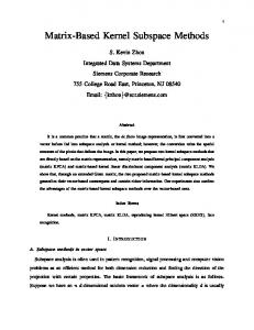
to each other. DC contains only the essential component for discriminating all the classes, since it is orthogonal to the principal component subspace MC which represents the principal component of all the class subspaces. Figure 6 shows the basis vectors of a 6-dimensional D3 between the 3-dimensional illumination subspaces of three planes with three small and one large hemispheres. The large hemispheres are put at the center, and the other three small hemispheres are put at each corner. The visualization result shows that the basis vectors of the D3 contain no information on the two common hemispheres (the small hemisphere at the upper left and the large hemisphere at the center) but retaining information of the other hemispheres as a difference. Figure 7 shows the orthonormal basis vectors of M128 and D128 of 128 16-dimensional illumination subspaces of the front faces of 128 subjects from the CMU Multi-PIE database [36]. This database consists of face images of 337 subjects, captured from 15 viewpoints with 20 lighting conditions in 4 recording sessions. In this visualization, we used front face images only of 128 subjects, with images collected across all four sessions. We took a sub-sampled image of size 16×16 pixels from an original image; we cropped this image by reference to the two inner corners of the eyes and the tip of the nose. The dimension of D128 was set to 211 according to a criterion that will be discussed next. 5.2
Selection of the optimal dimension of GDS
To consider how to select the optimal dimension of a GDS, we measured how the canonical angles between illumination subspaces are expanded by projecting them onto the
GDS. As the measure, we introduced the orthogonal degree, ω = 1.0 − S¯, between two projected subspaces over all the pairs, where S¯ is the mean of the similarities S in Eq. (2). As the relationship between the subspaces approaches perfect orthogonality, ω approaches 1.0. In addition, we measured three performance indexes: class separability, error equal rate (EER), and recognition error rate (ER), to examine the extent to which the orthogonal degree corresponds to the discriminative ability of the GDS. Class separability represents the ratio of the similarities within classes and that between classes, and is equivalent to the Fisher criterion. The recognition performance is higher as the separability is closer to 1.0. These indexes were measured by applying MSM to the projected testing subspaces while varying the dimension of the GDS from 256 to 60. The reference subspace of each subject was generated from 20 front face images in a session subset of the dataset used in the preceding subsection, and the testing subspaces were generated from the subsets in the remaining three sessions. The value of ω was also measured by using the three testing subsets as the reference subspaces. We repeated the above measurements four times by changing the combination of the reference and testing subspaces. Finally, we used the means of all the indexes as the final values of ω and as three performance indexes. Figure 8 shows changes in the resulting indexes against the dimension of the GDS. When the dimension is 256, all the indexes are the same as for MSM. Here note that ω was calculated as a predictive value by using just the reference subspaces in the learning phase. The three indexes were the actual values measured using both the reference and testing subspaces in testing phase. The graph indicates clearly that the trend of the value of ω corresponds well to those of the three performance indexes. In particular, it is worth noting that all the indexes reach a maximum near 211 dimensions, at which ω has achieved a maximum value of 0.89 (ω is 0.31 without projection).
7 0.8
6.2
0.7
We generate Nd -dimensional KGDS Dϕ from the set of C C N -dimensional nonlinear class subspaces {Vk }k=1 . The orthonormal basis of a KGDS can be obtained from all the orthonormal basis vectors of all the nonlinear subspaces; that is, the C×N basis vectors are used to find the orthonormal basis. This calculation is equivalent to applying PCA to all basis vectors. Let E be the matrix that contains all C the basis vectors as columns: E = [e11 . . . e1N . . . eC 1 . . . eN ]. Then, we solve the eigenvalue problem of the matrix D, defined as ET E. In the calculation of each element of the matrix D, the inner product between the ith orthonormal basis vector eki of the subspace of class k and the j th ′ orthonormal basis vector ekj of the subspace of class k ′ can be obtained as the linear combination of kernel functions ′ k(xkl , xki′ ) as follows:
ϕ
Value of each index
0.6 0.5 0.4 0.3
Orthogonality degree Class separability Error equal rate Error rate
0.2 0.1 0 256 240
220
200
180
160
140
120
100
80
60
Dimension of generalized difference subspace Fig. 8. Changes in the orthogonal degree between the projected subspaces and three performance indexes against the dimension of the GDS.
In the previous case (Figure 6), ω achieved a maximum of 0.73 at dimension 6 of the GDS, at which dimension the differences among the three objects appeared most clearly. In the case of four 3-dimensional subspaces of four 3D objects, ω achieved a maximum of 0.88 at dimension 9, at which dimension the differences among the objects were most clear. These observations lead to an idea: we should select the dimension at which the value of ω is maximum. This criterion is easy to measure, and can be accurately estimated even from a subset of all the class reference subspaces.
6
Generation of KGDS
N ONLINEAR KERNEL GENERALIZED DIFFER -
ENCE SUBSPACE
In this section, to deal with a set of multi-view images of a 3D object, we extend the GDS to nonlinear kernel GDS (KGDS) by using nonlinear kernel principal component analysis (KPCA) [23].
′
(eki · ekj ) = = =
(
2
. The vector of aki is normalized to satisfy
L ∑
′
′
akjl′ ϕ(xkl′ ))
(10)
l′ =1 ′
′
akil akjl′ (ϕ(xkl ) · ϕ(xki′ ))
l=1 l′ =1 L L ∑ ∑
′
′
akil akjl′ k(xkl , xkl′ ).
(11) (12)
l=1 l′ =1 ϕ
The ith orthonormal basis vector di of the KGDS Dϕ can be C×N represented as a linear combination of the vectors {Ej }j=1 , ∑C×N ϕ i.e. di = j=1 bij Ej where Ej indicates the j th column of the matrix E, and the weighting coefficient bij is the j th component of the eigenvector bi that corresponds to the ith smallest eigenvalue βi of the matrix D under the condition that the vector bi is normalized to satisfy that βi (bi · bi )=1. Ej corresponds to the η(j)th basis vector of class ζ(j), where η(j) = mod(j −1, N )+1 and ζ(j) = floor(j −1/N )+ 1. The above notation for dϕi may be written as follows: C×N ∑
bij Ej
=
j=1
C×N ∑
L ∑
bij
j=1
ζ(j)
ζ(j)
ζ(j)
ζ(j)
aη(j)l ϕ(xl
)
(13)
).
(14)
l=1
C×N L ∑ ∑
bij aη(j)l ϕ(xl
j=1 l=1
6.1 Generation of nonlinear class subspaces
exp − ||x−y|| σ2 k k λi (ai · ai )=1.
akil ϕ(xkl ) ·
l=1 L ∑ L ∑
= Let ϕ be the nonlinear function that maps the patterns x = (x1 , . . . , xf )T of an f -dimensional input space I onto an fϕ -dimensional feature space F , ϕ : Rf → Rfϕ , x → ϕ(x), where fϕ ≫ f . Given an N -dimensional nonlinear subspace Vk of class k generated by applying KPCA to L training patterns k N {xkl }L l=1 , the N orthonormal basis vectors {ei }i=1 , which span the nonlinear subspace Vk , can be represented by the ∑L k k k linear combination of {ϕ(xkl )}L l=1 as ei = l=1 ail ϕ(xl ), k where the coefficient ail is the lth component of the eigenvector aki corresponding to the ith largest eigenvalue λi of the L×L Gram matrix K. The elements of matrix K are defined as [kll′ ], where kll′ = (ϕ(xkl ) · ϕ(xkl′ )) = k(xkl(, xkl′ ). We use ) an exponential kernel function k(x, y) =
L ∑
6.3 Projection onto KDS It is impossible to visualize the orthonormal basis vectors dϕi of the KGDS Dϕ . However, the projection τ (ϕ(x)) of ϕ the mapped pattern ϕ(x) onto the basis vectors di can be calculated from an input pattern x and all L×C training patterns {xkl }L l=1 (k = 1, . . ., C) as follows:
(ϕ(x) · dϕi ) =
C×N L ∑ ∑
ζ(j)
ζ(j)
) · ϕ(x)) (15)
ζ(j)
(16)
bij aη(j)l (ϕ(xl
j=1 l=1
=
C×N L ∑ ∑
ζ(j)
bij aη(j)l k(xl
, x),
j=1 l=1 ζ(j)
where compute k(xl , x) through k(x, y) = ) ( we can2easily . Finally, the projection τ (ϕ(x)) of the exp − ∥x−y∥ σ2
8
Ndϕ (