EUROPEAN ORGANIZATION FOR NUCLEAR RESEARCH CERN ⎯ BEAMS DEPARTMENT
CERN-BE-2009-016 BI
Digital BPM Systems for Hadron Accelerators J. Belleman, S. Bart-Pedersen, G. Kasprowicz, U. Raich CERN – Geneva, Switzerland
01/05/2009
CERN-BE-2009-016
Abstract The CERN Proton Synchrotron has been fitted with a new trajectory measurement system (TMS) [2]. Analogue signals from forty beam position monitors are digitized at 125MS/s, and then further treated entirely in the digital domain to derive the positions of all individual particle bunches on the fly. Large FPGAs handle all digital processing. The system fits in fourteen plug-in modules distributed over three half-width cPCI crates. Data are stored in circular buffers of large enough size to keep a fewseconds-worth of position data. Multiple clients can then request selected portions of the data, possibly representing many thousands of consecutive turns, for display on operator consoles. The system uses digital phase-locked loops to derive its beamlocked timing reference. Programmable state machines, driven by accelerator timing pulses and information from the accelerator control system, direct the order of operations. The cPCI crates are connected to a standard Linux computer by means of a private Gigabit Ethernet segment. Dedicated server software, running under Linux, knits the system into a coherent whole.
Paper presented at DIPAC’09 Conference – 25-27 May 2009 /Basel - CH .
Geneva, Switzerland June, 2009
DIGITAL BPM SYSTEMS FOR HADRON ACCELERATORS∗ J. Belleman† , S. Bart-Pedersen, G. Kasprowicz, U. Raich, CERN, Geneva, Switzerland
Abstract
Bus or network
The CERN Proton Synchrotron has been fitted with a new trajectory measurement system (TMS) [2]. Analogue signals from forty beam position monitors are digitized at 125 MS/s, and then further treated entirely in the digital domain to derive the positions of all individual particle bunches on the fly. Large FPGAs handle all digital processing. The system fits in fourteen plug-in modules distributed over three half-width cPCI crates. Data are stored in circular buffers of large enough size to keep a few seconds-worth of position data. Multiple clients can then request selected portions of the data, possibly representing many thousands of consecutive turns, for display on operator consoles. The system uses digital phase-locked loops to derive its beamlocked timing reference. Programmable state machines, driven by accelerator timing pulses and information from the accelerator control system, direct the order of operations. The cPCI crates are connected to a standard Linux computer by means of a private Gigabit Ethernet segment. Dedicated server software, running under Linux, knits the system into a coherent whole.
Σ X Y
data 3 x ADC 14 bits 125MS/s
3 x 14 FPGA
address
SCY CAL−START CAL−STOP INJ H−CHANGE ECY
Memory 256MB
10MHz Frev
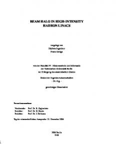
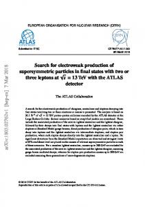
Figure 1: Signal processing block diagram for one BPM. Network System controller (Basically a Linux PC)
VME/FESA timing/gain ctrl
Network switch
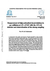
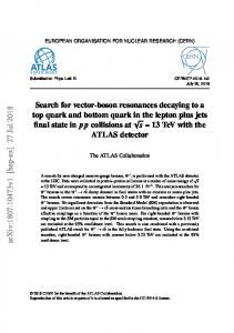
INTRODUCTION The CERN Proton Synchrotron (PS) is a 200 m diameter 26 GeV alternating-gradient synchrotron built in 1959. It is part of the injector complex that prepares protons and 208 Pb ions for the LHC. The PS is equipped with forty electrostatic BPMs, each delivering three analogue signals: A horizontal and vertical displacement signal, Δx , Δy and an overall sum Σ. The 120 BPM signal channels are digitized using LTC2255, 14 bit, 125 MS/s ADCs, and the digital sample streams are then further processed into per-bunch positions using Xilinx Virtex-4 FPGAs. Results are stored into a memory large enough to store several seconds worth of data (Fig. 1). Nine channels, corresponding to three BPMs, are combined on a single cPCI digitizer module. This module is the only board that has been custom designed for this application. Fourteen of these modules are distributed over three half-width cPCI crates (Fig. 2). Each crate also contains a standard, off-the-shelf Concurrent Technologies PP410 module controller. A private Gigabit Ethernet segment connects the module controllers to a Supermicro Core TM i7, ∗ We
acknowledge the support of the European Community-Research Infrastructure Action under the FP6 ”Structuring the European Research Area” programme (DIRAC secondary-Beams, contract number 515873) †
[email protected]
Module controller Timing patch PU processing engines 8−slot cPCI
Figure 2: TMS block diagram. model 5046-XB system controller. The system controller also acts as a BOOTP server and NFS file server for the cPCI processor boards. The three module controllers and the system controller all run Fedora Linux. A server daemon running on the system controller provides an RPCbased interface through which the whole system appears as a coherent single instrument. The server can handle multiple simultaneous independent clients. The system was built to CERN’s specification by British industry [1]. For reasons of standardization and uniformity, a server based on CERN’s Front-End Software Architecture (FESA) mediates between the TMS and control room ap-
plications. The FESA server is responsible for informing the TMS of the accelerating cycle to be treated at the appropriate time, and for collecting and publishing data requested by the control room operators. It also controls BPM pre-amplifier settings, maintains and applies calibration data and provides access to diagnostic information. It runs on a processor installed in a separate VME crate, with network connections to both the TMS private segment and to the accelerator control network. The VME crate furthermore contains the hardware to generate the various timing pulses and interrupts, and to control the BPM preamplifiers.
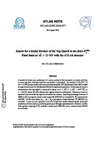
Each of the BPM processing channels implements a numerical Phase Locked Loop (PLL) algorithm, locking a Numerically Controlled Oscillator (NCO) to the revolution frequency Frev prior to beam injection, and to the BPM Σ signal afterward (Fig. 4). All required beam-synchronous PU Σ Frev MSB LO1 Finj
Phase Table
NCO
LO2 Gate BLR
PU azimuth
Phase error
State Regulator
SIGNAL PROCESSING The system determines the position of the centre of charge of each particle bunch by integrating each of the BPM signals, Σ, Δx and Δy over the length of the bunch and normalizing against Σ [2][3]. X = Sx
Δx + Ex Σ
2
3
4
5
6
7
Fref
Gate
BLR LO
Regulator BLR filter
1
(1)
The integration is implemented as a simple addition of the samples belonging to a given bunch. The integrals are then piped into a circular buffer. The actual position calculation (1), which also involves scaling (Sx ) and a correction for BPM alignment errors (Ex ), is deferred to the time at which data is actually requested for display. Due to the high-pass frequency response of the BPMs, the base line of the signal droops so that the integral over a full bunch period would tend to zero. To fix this, base line restoration is applied before integration. This is done by passing the ADC data through a numerical filter with a response complementary to the high-pass characteristic of the BPM channel (Fig. 3). The base line is then nominally
in
PU Σ
out
Figure 3: Principle of Base Line Restoration. flat, but at an indeterminate value, potentially very large. A Base Line Restoration timing signal (BLR), is used to collect samples from the baseline to be pumped into a feedback regulator that drives the baseline toward zero.
Beam-synchronous Timing The bunch-wise processing of the input signals requires beam-synchronous timing signals. The task is complicated by the use of bunch splitting or merging, changing the harmonic number of the machine, possibly several times in a single cycle.
one revolution
Figure 4: Principle of beam-synchronous signal generation. signals are then derived from this PLL. The LO signal is needed to compare the phase of the Σ signal with the reconstructed reference frequency to close the loop. A Gate signal designates the samples belonging to each bunch. A BLR signal is generated for Base Line Restitution.
Event Sequencing From the point of view of the TMS, the acceleration cycle is punctuated by six events produced by the accelerator timing system (Fig. 1). The events mark the start and end of an acceleration cycle, the beginning and end of a calibration period, beam injection, and the instants at which bunch splitting occurs. Some events may happen more than once in a given acceleration cycle. None of these events are under the control of any of the clients of the TMS, thus decoupling the system’s behaviour from the clients’ whims. The events drive a state machine that can be freely programmed to traverse any desired sequence (Fig. 5). A few states are reserved as Start, End, or Error states. Each state has an associated internal signal routing –the switches in Fig. 4–, and tables for the generation of LO, Gate and BLR signals. The appropriate state machine program is selected and loaded prior to the start of each acceleration cycle. The state machine programs are kept in a number of small text files, one for each type of acceleration cycle. Loading one takes about 20 ms. Of the six timing events used, only one, the injection trigger (INJ), needs to be accurate to within one RF period, thus marking the first RF bucket to be filled. All the other timing pulses are synchronized using the site-wide 10 MHz standard clock. The ADC sampling clock and all of the
INJ INJ INJ CalStrt
Start
Cal
CalStp
[mm] HCH
H8
40 30
H16
20
Wait
10
CalStp
0
Figure 5: A state machine controls the system’s behaviour according to the occurrence of accelerator timing events.
−10 −20 −30
signal processing are also locked to this standard, so the whole system marches to the same beat. The effect of an event is delayed according to the azimuthal position of each BPM with respect to the injection point, thus ensuring the same data structure in every channel.
SOME MEASURED RESULTS
−40
10
20
30
40
50
60
70
80
90
100
section
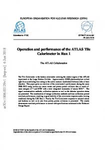
Figure 7: A 25-turn trajectory of a single-bunch P + beam a few thousand turns after injection. The beam now follows the same trajectory turn after turn. [mm]
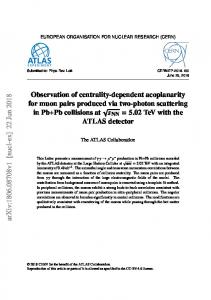
While no in-depth comparison of the new TMS with the old system has yet been completed, it has delivered a number of interesting results. The possibility of the TMS to acquire over many, many turns is very useful for injection and ejection studies. The system will also deliver data to the Automatic Beam Steering (ABS), which calculates field corrections in order to optimize the beam injection trajectory. A few examples of P + beam acquisitions are shown in Figs. 6, 7 and 8.
0
40 30 20 10 0
−10 −20 −30 −40
0
100
200
300
400
500
600
700
800
900
1000
turn
[mm]
40
Figure 8: The position of a P + bunch in PU43 over 1000 turns starting from injection, showing injection oscillations and the collapse of the injection bump.
30 20 10 0 −10 −20 −30 −40
0
10
20
30
40
50
60
70
80
90
100
section
Figure 6: A 1000-turn injection trajectory of a single-bunch P + beam. The beam is injected in section 43. During the first few-hundred turns, it makes large excursions around its equilibrium orbit.
CONCLUSION The new trajectory measurement system delivers both individual bunch trajectories and averaged orbits, over a large number of consecutive turns [4]. It advantageously replaces the old CODD trajectory measurement system, which could only measure a single two-turn trajectory every 5 ms, and which was blind during bunch splitting. The TMS has been running since September 2008. Software to allow convenient use by the control room crew is nearing completion. Measurements that previously needed painstaking collection of small parcels of data spread over many successive acceleration cycles can now be acquired
in a few seconds and in a single shot. The system has been demonstrated to have no trouble delivering over 700000 points of contiguous trajectory data, or full-cycle turn-byturn positions from selected BPMs. However, network bandwidth, post-processing power and FESA overhead impose a limit of 200000 points delivered to the end user.
REFERENCES [1] Alpha-Data/Beam Ltd., “The CERN Trajectory Measurement System: Support and Development Information”, http://portal.beam.ltd.uk/support/cern [2] J.M. Belleman, “A New Trajectory Measurement System for the CERN Proton Synchrotron”, DIPAC’05, Lyon, June 2005, CTTM01, pp. 137-139, http://www.JACoW.org [3] G. Kasprowicz, J.M. Belleman, U. Raich, “Digital Beam Trajectory and Orbit System for the CERN Proton Synchrotron”, DIPAC’07, Mestre, May 2007, TUPB09, pp. 7577, http://www.JACoW.org [4] E. Bravin, J. Belleman, M. Chanel, M. Ludwig, E. M´etral, G. M´etral, J.P Potier, U. Raich, R, Scrivens, R. Steerenberg, “Specification of the Beam Position Measurement in the PS Machine”, AB-Note-2004-001-ABP, January 2005.