Walsh-Hadamard transformation [I] to FIR and IIR filtering is investi- gated. It is shown ... The block diagram of the proposed structure is given in Fig. 1. For every ...
150
IEEE TRANSACTIONS ON CIRCUITS AND SYSTEMS, VOL.
31, NO. 1,JANUARY 1990
Circuits and Systems Letters Digital Filters Based on Recursive Walsh-Hadamard Transformation
11. PROPERTIES OF THE RECURSIVE WALSH-HADAMARD TRANSFORMER
GABOR PECELI AND BELA FEHER
Since the overall behavior of the transformer in Fig. 1 is time invariant, for the analysis we can replace the internally timevariant components, in every channel, by the transfer function Km(z),m = O , l ; . . , N - l , as it is shown in Fig. 2. K,,,(z) is a function of real coefficients, and can be decomposed as a linear combination of elementary transfer functions having one (complex) pole located on the unit circle [9]. These resonator-pole positions are the Nth roots of the unity ( z n , n = 0,l; . ., N - l), and the “weight” of these elementary transfer functions comes from the Fourier series expansion of the Walsh-Hadamard functions applied. If the input signal of the transformer is bandlimited in the usual sense, i.e., by one half of the sampling frequency, the effect of “modulating” by the discrete Walsh functions is equivalent to the effect of a limited number of discrete harmonical components. Thus
Absfrucf-In this paper the applicability of the recursive Walsh-Hadamard transformation [I] to FIR and IIR filtering is investigated. It is shown that using the recently introduced common structure for recursive transforms [2] the usual frequency-domain FIR filtering problem can be easily converted into a Walsh sequency-domain filtering problem. It is also shown that a simple modification of this structure results in a possible alternative for IIR filter implementations.
I. INTRODUCTION It is well known from the literature that the Walsh-Hadamard transformation (WHT) [3], and especially its fast version, can be efficiently used for the calculation of the discrete Fourier transformation (DFT) [4], for implementing adaptive filters [5], and for DFT spectrum filter realizations [6]. In this paper, the recursive form of the WHT is investigated, and for its implementation the recently introduced common structure for recursive transformations [2] is suggested. The derivation of this common structure is based on the state variable formulation and the results of the observer theory [l], while its applicability to FIR and IIR filtering operations comes from the generalization of the “frequency sampling method‘’ [7]. The block diagram of the proposed structure i s given in Fig. 1. For every discrete transformation to provide a dead-beat observer behavior, the { c p t ( k ) }and { g , , , ( k ) } , m = O , l ; . . , N - l , values should be the k th components of the basis and reciprocal basis vectors of the transformation, respectively [2]. In this paper we concentrate on the recursive WalshHadamard transformation [l], which is obtained if in Fig. 1:
N-1
Km(z)
=
C
urnnHn(z)
(2)
n=O
where { U,,,, }, m, n = 0,1,. . ., N - 1, are the appropriate weighting coefficients, and
is the elementary transfer function. It is interesting to note that for the recursive DFT K,,,(z) = H,(z), rn = 0,l;. ., N - 1 [2]. Concerning the stability of the recursive structure (see Fig. 2) the transfer function from the input to point P should be investigated. The stability of this feedback loop in the linear sense comes from the fact that all the poles of the transfer function
cn,(k ) = wa/(m, k )
1
g,,( k ) =
y w 4 m,k )
,
m=O,l;..,N-l
(1)
and as usual, N is an integer power of 2. This transformation is of practical interest, since multiplication by (1) can be reduced to additions, and a single division by N, that is a simple shift operation. In Section I1 the properties of the recursive WHT structure are examined. It is shown what is the relation between the recursive DFT and WHT, and what is the condition of “structural passivity” [8] for the recursive WHT. Section I11 presents a new method for implenienting IIR filters. This method is based on a modified form of the recursive WHT structure. In Section IV some aspects of the hardware realization are discussed. Manuscript received March 3, 1989. This letter was recommended by Associate Editor T. R. Viswanathan. The authors are with the Department of Measurement and Instrument Engineering. Technical University of Budapest, H-1521 Budapest, Hungary. IEEE Log Number R929503. I
are at the origin of the z-plane unless coefficient quantization errors occur. Note, however, that for the recursive Walsh-Hadamard transformer the only source of coefficient quantization error is the division by N, and if we apply “magnitude-truncation” strategy, it is easy to show, that both the frequency domain criteria given in [lo], and the structural boundedness property detailed in [8] can be fulfilled. This later property is simply due to the fact that Hp(z) in (4) implements an all-pass transfer function, the magnitude of which can not exceed the unity if “magnitude-truncation” is applied. Thus in the WalshHadamard transformer implemented as in Fig. 1, the zero-input limit cycles can be suppressed (see also [ll]). The implementation of FIR filters using this transformer is rather straightforward, since only the appropriate linear combination of the transformer outputs should be generated. These
OO98-4094/90/0100-0150$01 .OO 01990 IEEE
IEEE TRANSACTIONS ON CIRCUITSAND SYSTEMS,VOL. 31, NO.
1, JANUARY 1990 -1
151
P
walk)
+ v)
c al a E 0 v
C
Fig. 1 .
&
4wll kl
The suggested common structure.
VI
c
c W
c 0 a
-
-
E, -e
Input
output
c 0
Input
output
WN-1
0 ._ m X
I
L
0
Fig. 2.
“Time-invariant” Walsh-Hadamard transformer.
Fig. 3.
“ taps” do not influence the stability of the transformer structure. Thus the transfer function for an FIR filter has the form of
where the d‘ and w,:,n = 0,l;. ., N -1, are the weightingcoefficients. The calculation of these coefficients is relatively simple. By introducing { U,,,, } = V , w = [wo,w l , . . ., wN-l ] T , w’ = [W~,W;;..,W~-~]‘, where w,,= H ( z , , ) ,
m=O,l;..,N-l
(6)
111.
*’
Modified Walsh-Hadamard transformer.
THE
IMPLEMENTATION OF IIR FILTERS
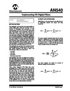
If we introduce additional weighting coefficients into the transformer structure like in Fig. 3, the implementation of IIR filters is also possible. For the recursive Fourier transformation these coefficients are given by
where { p , , } , n = 0,l; . ., N - 1, are the poles of the filter (see [ 2 ] ) .The number y, is usually complex, but if the poles are real numbers, or occur in complex-conjugate pairs, the complex conjugate of y, will also appear. Let us denote Y = [yo, y1; . ., y N - ] I T , Y’= [YO,VI’,. . .. vl; I]‘, and apply the structure of Fig. 3, then we have for the IIR filter ~
as for the “frequency sampling method” [7], we have w’= v- T w
(7)
(here T Tstands for “transpose of the inverse of V ” ) , and finally, d’ = H ( 0 ) .
(8)
The calculation of V is straightforward
V= {
= m-1
( 9)
where W is the Walsh-Hadamard, while F is the discrete Fourier transformation matrix.
The tap coefficients can be derived from (7) if w,,,and wL3 are replaced by w,y, and wityA, respectively, ( m = 0,1,. . ., N - 1). It is interesting to note that if the transfer function to be implemented is of real coefficients, then both the wLz and yLl values ( m = 0,1,. . ., N - 1) will be real numbers. It is worth mentioning, however, that the introduction of the y:, parameters destroys the orthogonality of the transformer structure, and thus the general criteria of nonlinear stability and low sensitivity [8] are not fulfilled. Still for its computational simplicity in certain cases even this Walsh-Hadamard transformer can be suitable for IIR filter realizations.
-
I
\ r
\--
152
IEEE TRANSACTIONS ON CIRCUITS AND SYSTEMS, VOL.
IV. I~WLEMENTATIONAL ASPECTS The hardware implementation of the recursive WalshHadamard transformer is relatively simple, since it requires only additions and a single shift operation to perform division by N . The Walsh function samples can be stored in a memory, or can be generated by a simple digital circuit. To implement FIR and IIR filters the multiplications by d‘, wh, and y;, m = 0,l; . ., N - 1, obviously can not be avoided, however, this structure is still canonic with respect to the number of (nontrivial) multiplications. The recursive Walsh-Hadamard transformer has been implemented by the authors on a microprogrammable signal processor based on bit-sliced elements [12]. It was found that for this hardware, and for every input sample, the number of microprogram steps to perform Walsh-Hadamard transformation is S ( N ) =6N+1og2N+13, where N equals the transform size. The number S ( N ) includes the steps required for the Walsh function generation as well. V. CONCLUSIONS In this paper the applicability of the recursive WalshHadamard transformer has been investigated. It turned out that using the common structure proposed, both FIR and IIR filters can be efficiently implemented, and that for the transformer itself, and for FIR filters, the structural boundedness of the common feedback loop can be easily guaranteed. This property implies the ability of suppressing zero-input limit cycles. The generalization of these results for arbitrary discrete transformation is straightforward.
REFERENCES
151
[9] [lo]
[ll] 1121
37, NO.
1 , JANUARY
1990
The Infeasibility of a Zero-Current Switching Class E Amplifier KELLY J. HERMAN AND ROBERT E. ZULINSKI Abstract -It has been shown that a class E amplifier may be configured to provide nearly 1Wpercent efficiency and zero-current or zero-voltage switching. A particular configuration, which supplies zero-current-switching when the transistor output capacitance is zero, is considered for the case when the transistor output capacitance is greater than zero. Equations for the switch voltage and current, the dc input voltage and current, the output voltage and current and powers are determined for the amplifier. The equations show that with this configuration, a zero-current-switching class E amplifier can not be physically realized.
1. INTRODUCTION Class E switching-mode amplifiers provide efficiencies approaching 100 percent by reducing the power dissipated in the active device switch during one of the switch transitions. Conceptually this may be accomplished by reducing the switch voltage or current to zero during the off-to-on or on-to-off transition, respectively. For a zero-current-switching class E amplifier with minimum power dissipation the three following conditions are needed: i) zero switch current at the on-to-off transition; ii) zero slope for the current at the on-to-off transition; iii) zero switch current at the off-to-on transition. Class E amplifiers can be configured to provide zero-currentswitching when the transistor has zero output capacitance [1]-[4]. At high frequencies the internal capacitance of the transistor is no longer negligible. It is the purpose of this letter to show the infeasibility of a zero-current-switching amplifier with a nonzero transistor output capacitance.
11. CIRCUITDESCRIPTION
G. H. Hostetter. “Recursive computation of Walsh-Hadamard transformation,” Signal Processing, vol. 8, no. 1, pp. 41-49, Feb. 1985. G. Pkeli. “A common structure for recursive discrete transforms,” I E E E Truns. Circuits Sysr., vol. CAS-33, pp. 1035-1036, Oct. 1986. N. Ahmed and K. R. Rao, “Orthogonal transforms for digital signal processing,” Berlin: Springer-Verlag, 1975. Y. Tadokoro and T. Higuchi, “Discrete Fourier transform via Walsh transform,’’ IEEE Trans. Acoustics, Speech, Signal Processing, vol. ASSP-27, pp. 295-296, June 1979. W. K. Jenkins and J. R. Kreidle, “Adaptive digital filters using the Walsh-Hadamard transform,” in Proc. 1986 Int. Symp. on Circuits and xvstems, pp. 875-878. C. J. Zarowski, M. Yunik, and G. 0. Martens, “DFT spectrum filtering,” IEEE Truns. Acoust., Speech, Signal Processing, vol. ASSP-36, pp. 461-470, Apr. 1988. L. R. Rabiner and B. Gold, Theory and Application of Digital Signal Processing. Englewood Cliffs, NJ: Prentice-Hall, p. 47, 1975. P. P. Vaidyanathan. “The discrete-time bounded-real lemma in digital filtering,” IEEE Trans. Circuits Syst., vol. CAS-32, pp. 918-924, Sept. 1985. M. Vetterli. “Tree structures for orthogonal transforms and applications to the Hadamard transform,” Signal Processing, vol. 5, no. 6, pp. 473-484, Nov. 1983. T. Claasen, W. F. G. Mecklenbrauker, and J. B. H. Peek, “Frequency domain criteria for the absence of zero-ineut limit cvcles in nonlinear discrete-time systems.” IEEE Trans. Czrcuits Syst., vol. CAS-22, pp. 232-239, Mar. 1915. G. Pkeli, “Resonator-based digital filters,” IEEE Trans. Circuits Syst., vol. 36. pp. 156-159. Jan. 1989. K. Toth. B. Feher, Z. Szalai, and Zs. Abonyi, “High-speed microprcgrammable digital signal processor based on bit-sliced elements,” Proc. pP85. Fourth Symp. on Microcomputer and Microprocessor Applications, Budapest, Hungary, pp. 27-37.1985.
The basic class E amplifier (Fig. 1) consists of an active device operated as a switch at the input frequency w and a load network which includes a capacitor shunting the active device and a series RLC output circuit. Circuit operation is determined by the switch when on and by the transient response of the load network when the switch is off. The analytical description of the circuit begins with the following assumptions. 1) The load current is sinusoidal at the output frequency. This is approached with a large Q of the output circuit. 2) The active device acts as an ideal switch: thus any nonzero shunt capacitor voltage present at switch turn-on is discharged by a current impulse. The switch is bidirectional, i.e., it allows positive and negative current when on and withstands positive and negative voltage when off. 3) The shunt capacitance includes device capacitance and is independent of device voltage. 4) All equivalent circuit elements are ideal. Manuscript received May 3, 1989; revised June 6, 1989. This material was based upon work supported by the National Science Foundation, under Grant ECS-8707669. This letter was recommended by Associate Editor T. R. Viswasnathan. The authors are with the Department of Electrical Engineering, College of Engineering, Michigan Technological University, Houghton. MI 49931. IEEE Log Number 8929941.
0098-4094/90/0100-0152$01.00 01990 IEEE