IEEE TRANSACTIONS ON CIRCUITS AND SYSTEMSâII: ANALOG AND DIGITAL SIGNAL PROCESSING, VOL. 47, NO. ... imators, and multi-rate narrow-band filters; see, e.g., [11]â[14]. In addition to being .... in (16), we also note that and.
48
IEEE TRANSACTIONS ON CIRCUITS AND SYSTEMS—II: ANALOG AND DIGITAL SIGNAL PROCESSING, VOL. 47, NO. 1, JANUARY 2000
High-Speed Recursive Digital Filters Based on the Frequency-Response Masking Approach Håkan Johansson, Member, IEEE, and Lars Wanhammar, Member, IEEE
Abstract—The frequency-response masking approach for highspeed recursive infinite-impulse response (IIR) digital filters is introduced. In this approach, the overall filter consists of a periodic model filter, its power-complementary periodic filter, and two masking filters. The model filters are composed of two all-pass filters in parallel, whereas the masking filters are linear-phase finite-impulse response (FIR) filters. The transfer functions of the all-pass filters are functions of which implies that the maximal sample frequency for the overall filter is times that of the corresponding conventional IIR filter. The maximal sample frequency can be increased to an arbitrary level for arbitrary bandwidths. The overall filter can be designed by separately optimizing the model and masking filters with the aid of conventional approximation techniques. The obtained overall filter also serves as a good initial filter for further optimization. Both nonlinear-phase and approximately linear-phase filters are considered. By using the new approach, the potential problems of pole–zero cancellations, which are inherent in algorithm transformation techniques, are avoided. Further, robust filters under finite-arithmetic conditions can always be obtained by using wave-digital all-pass filters and nonrecursive FIR filters. Several design examples are included illustrating the properties of the new filters.
I. INTRODUCTION ECURSIVE infinite-impulse response (IIR) digital filters1 have a drawback in that they restrict the sample frequency at which an implementation of the filters can operate. This may affect not only the speed but also the power consumption, since excess speed can be traded for low power consumption through the use of power-supply voltage-scaling techniques [2]. The sample frequency bound is referred to as the maximal sample frequency, and is determined by the ratio between the number of delay elements and the operational latency in the critical loop of the filter realization [3]–[5]. One way to increase this bound is thus to increase the number of delay elements in the critical loop. This can be achieved using either algorithm-transformation techniques or constrained filter-design techniques. To the former belong the well-known clustered and scattered lookahead techniques and block realization; see, e.g., [6]–[8] for a review and a comprehensive reference list. Algorithm transformation techniques are based upon pole and zero cancellations, which can be achieved theoretically, but under finite-arithmetic conditions, the cancellations become inexact, which may impose problems such as increased coefficient sensitivity and
R
Manuscript received March 16, 1999; revised September 1999. This paper was recommended by Associate Editor P. Diniz. The authors are with the Department of Electrical Engineering, Linköping University, SE-581 83, Linköping, Sweden. Publisher Item Identifier S 1057-7130(00)00584-X. 1Although recursive filters can be either IIR or FIR [1], in this paper they are understood to be IIR.
M=
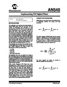
Fig. 1. Structure and illustration of magnitude functions for high-speed narrow-band filters (with 4).
time-variant behavior [9], [10]. Pole and zero cancellations can be circumvented by using constrained filter-design techniques in which the denominator polynomial of the transfer function . The corresponding realis restricted to be a function of delay elements in its critical loop, reization has at least sulting in an -fold increase of the maximal sample frequency. Over the past decades, a number of such techniques have been proposed, mainly in order to obtain efficient interpolators, decimators, and multi-rate narrow-band filters; see, e.g., [11]–[14]. In addition to being suitable only for narrow-band filters, these techniques have a drawback in that they restrict the choice of filter structures because the transfer function is expressed as . An alternative is to make use of periodic and nonperiodic filters [8], [15]–[21]. For narrow-band filters, the transfer function is in the simplest case then of the form (1) and are here referred to as model and masking where filters, respectively. The masking filter extracts the desired image, and rejects the undesired images, from the periodic magnitude function (i.e., the magnitude function has a period of ) of the periodic model filter . This is illustrated in Fig. 1 for a low-pass filter design. This technique was originally introduced in order to reduce the complexity of finite-impulse response (FIR) filters with narrow transition bands [22]–[24]. (The filters are, in this case, commonly referred to as interpolated FIR filters). It has been used in [8], [15] to obtain high-speed narrow-band recursive filters by using an IIR filter for the model filter and an FIR filter for the masking filter. The case where both of the model and masking filters are IIR filters has been considered in [16], [17]. Wideband filters have also
1057–7130/00$10.00 © 2000 IEEE
JOHANSSON AND WANHAMMAR: HIGH-SPEED RECURSIVE DIGITAL FILTERS
been studied in [8], [16]–[19], in which a narrow-band filter in the form of (1) is connected in parallel with an all-pass filter. An advantage of using techniques based on periodic and nonperiodic filters is that there is a large freedom to choose structures for the model and masking filters that are well suited for the specification and problem at hand. Two obvious drawbacks of the techniques referred to above are, however, that they can only be used for narrow-band and wideband filters, and that the feasible increase of the maximal sample frequency is dependent upon the bandwidth. In this paper, we introduce the frequency-response masking approach which makes it possible to increase the maximal sample frequency to an arbitrary level, for arbitrary bandwidths [20]. This approach was originally introduced in [25] for FIR filters with narrow transition bands. In our case, the overall filter is composed of a periodic IIR model filter, its power-complementary periodic filter, and two linear-phase FIR masking filters. The model filters are realized as a parallel connection of two all-pass filters whose transfer , resulting in an -fold increase functions are functions of of the maximal sample frequency. Even if the IIR model filters are restricted to be realizable as a parallel connection of two all-pass filters, there is still a large freedom to choose structures with good properties since all-pass filters can be realized in many different ways [1], [26]. For example, wave-digital filters (WDF’s) can be used which makes it possible to maintain stability under finite-arithmetic conditions [27]–[30]. In this case, the model filters correspond to the well-known lattice WDF’s [30]–[32]. In addition, the all-pass filters can always be realized by cascading low-order sections, which is attractive from an implementation point of view. For the FIR masking filters, arbitrary (linear-phase) FIR filter structures can be used. It should be noted that the frequency-response masking approach has recently been used for high-speed multirate filters in [21]. In this paper, we consider theory and design of single-rate filters. Following this introduction, we introduce the new filters in Section II. Section III is devoted to filter design. In Section IV, some properties of the new filters are illustrated by means of several design examples. Finally, some concluding remarks are given in Section V.
II. PROPOSED FILTERS
49
Fig. 2. Illustration of magnitude functions in the frequency-response masking approach. (a) Model filters G(z ) and G (z ). (b) Periodic model filters G(z ) and G (z ). (c) Masking filters F (z ) and F (z ) for a Case-1 design. (d) Overall filter H (z ) for a Case-1 design. (e) Masking filters F (z ) and F (z ) for a Case-2 design. (f) Overall filter H (z ) for a Case-2 design.
where
In this section, we first recapitulate the frequency-response masking approach upon which the proposed filters are based. We then introduce the new filters, and finally derive some expressions for their frequency, magnitude, and phase responses, which are used in the succeeding sections.
A. Frequency-Response Masking In the frequency-response masking approach, the transfer can be written as function of the overall filter (2)
is some positive integer [25]. We refer to and as the model filter and complementary model filter, and as the masking filters. The respectively, and to latter extract one or several passbands of the periodic model and and , respectively. complementary model filters For a lowpass filter, typical magnitude responses for the model, masking, and overall filters are as shown in Fig. 2, where is some positive integer. The transition band of can be selected to equal one of the transition bands of either or . We refer to these two cases as Case 1 and Case and denote the passband and 2, respectively. Here, . The stopband edges, respectively, of the overall filter same notations are used for the model and masking filters , and but with additional superscripts , and , respectively.
50
IEEE TRANSACTIONS ON CIRCUITS AND SYSTEMS—II: ANALOG AND DIGITAL SIGNAL PROCESSING, VOL. 47, NO. 1, JANUARY 2000
For a Case-1 design, we see from Fig. 2 that, given the pass, the passband and stopband band and stopband edges of edges become, for
(3) and for
Fig. 3. Proposed filter structure where G (z ) and G (z ) are IIR all-pass filters, and F (z ) and F (z ) linear-phase FIR filters.
and
(4)
(5) For a Case-2 design, the passband and stopband edges become, for
Fig. 4. Alternative structure to that in Fig. 3 that enables a reduced computational complexity of the FIR masking filters. A(z ) = 0:5[F (z ) + F (z )] and B (z ) = 0:5[F (z ) F (z )].
0
and masking filters and , are all linear-phase FIR filters. In our approach, IIR model filters and linear-phase FIR masking filters are used. The basic principle remains the same but the design and properties of the overall filters differ from the FIR case. B. Filter Structures
(6) and for
In the proposed filters, the model filters are power complementary IIR filters being realizable as a parallel connection of two all-pass filters, whereas the masking filters are linear-phase FIR filters. The model filters can be expressed as
and (11) (7)
(8) The constant
and are stable all-pass filters. We assume where and are normalized such that their magnitude that responses always are bounded by one, which obviously is the . The overall transfer case if function is expressible as
is given by (9)
for a Case-1 design, and
(12) and denoting the linear-phase FIR masking with filters. The overall filter can be realized as shown in Fig. 3. The overall transfer function can also be written as (13)
(10) is the largest integer for a Case-2 design, where , whereas is the smallest smaller than [25]. For an arbitrary set of integer larger than , and , only one of (3) and (6) will ensure that [25]. The frequency-response masking approach has earlier only been used for FIR filters as a means to reduce the computational complexity when the transition band of the overall filter is narrow. In that context, the model filters and ,
where (14) A corresponding realization is shown in Fig. 4. The total comand is, in general, naturally equal to the plexity of and , but in cases where the total complexity of is close to , the total complexity can be bandwidth of reduced by using the structure in Fig. 4 (see Section III-D). In
JOHANSSON AND WANHAMMAR: HIGH-SPEED RECURSIVE DIGITAL FILTERS
51
the overall filters, the transfer functions of the IIR (all-pass) fil, which results in a maximal sample freters are functions of quency which is times that of conventional IIR filters [3]–[5].
3) Phase Response and Phase Error of : Instead of and it is possible to replace either with using with , or with and with . From (17)–(19), we see that neither of these three but only its substitutions affect the magnitude response of phase response. We therefore consider the following two different cases in which the overall filters are referred to as Type A and Type B filters, respectively. Type A: Type B: The remaining two cases need not be treated separately, since the overall filters there are the same as in the two cases under consideration, respectively, except for a sign inversion. as It is helpful to first rewrite the frequency response of
C. Frequency, Magnitude, and Phase Responses In this section, we derive some expressions for the frequency, magnitude, and phase responses of the individual and overall filters, which are used in the succeeding sections. , and 1) Frequency Responses of : It is readily established that the frequency responses of and can be written as
(21)
and where and all-pass filters and responses of
(15) denote the phase responses of the , respectively. The frequency can be written as (16)
being the (group and phase) delays in samand , respectively, and where and denote the zero-phase frequency responses of and , respectively [33]. Throughout this paper, it is asin (16)2 The frequency response sumed that can then be written as of
with ples of
and
and are given by (14). Since it is assumed where in (16), we also note that and that are linear-phase filters with the same delay as that of and . This means that the frequency responses of and can be written as (22) and denote, respectively, the zerowhere and [33]. It is now phase frequency responses of convenient to rewrite (21) as (23) where
for Type A filters,
for Type B filters, and
(17)
(24)
where The phase response of
can now be written as (25)
with and being the phase responses of and , respectively. the periodic all-pass filters : Using (15)–(18), it is easy 2) Magnitude Response of can be to conclude that the squared magnitude response of written as
, the term is small (see In the passband of Appendix B), and therefore, the phase response can in this re. This gion be approximated by can also be deduced intuitively by inspecting (12). One way of measuring the phase linearity is to use the phase error as given by [34] (26)
(19) Here, we have utilized that the model filters power complementary, i.e.,
and
are
denotes the passband where is some positive constant and is the difference beregion. That is, the phase error and the linear-phase function tween the phase response . Here, since the term in (25) has linear phase, it is convenient to write the phase error as
(20) which follows immediately from (15) since . 2When designing F (z ) and F (z ); it may turn out that they are not of equal order (i.e., K 6= K ). It is, however, easy to make them have equal orders (i.e., K = K ) by inserting extra delays into that one with the lowest order. The condition is that both filters are of either odd or even order.
(27) where
.
III. FILTER DESIGN In this section, we consider the design of the new filters introduced in Section II. Both unconstrained and constrained fil-
52
IEEE TRANSACTIONS ON CIRCUITS AND SYSTEMS—II: ANALOG AND DIGITAL SIGNAL PROCESSING, VOL. 47, NO. 1, JANUARY 2000
ters are studied. By unconstrained filters, we mean here that the masking filters are independent of each other. In the constrained filters, they are related to each other in order to reduce the computational complexity. The constrained filters can only be used . when the bandwidth of the overall filter is close to
but with additional superscripts respectively. Let the specification of
, and
,
be (31)
will meet the requireWe now deduce from (28)–(30) that , for a Case-1 design, satisfies ments of (31) if A. Unconstrained Filters (32) and are indeIn this case, the masking filters pendent of each other. We concentrate on the case in which is a low-pass filter. The extension to the overall filter high-pass filters, and also bandpass and bandstop filters with certain symmetry restrictions, is straightforward. To see how to and , and masking filters design the model filters and , such that the overall filter meets its requirements, we will first derive some bounds on the magnitude . response of and are alThe magnitude responses of ways bounded by one since by assumption . Without loss of generality, we assume that the and are also bounded by magnitude responses of one. The following can now be shown (see Appendix A):
and
(33) and
(29) and in Case 1, and and where in Case 2. Thus, for a Case–1 (Case–2) design, the passband in the band is in the ripple of worst case the sum of the passband ripples of and . Further, for a Case-1 (Case-2) design, has its transition band within the stopband region of . Using (19) we get (30) Hence, for a Case-1 (Case-2) design, the squared stopband in the band is, in the ripple of worst case, equal to the sum of the squared stopband ripples of and . can From the above observations, we conclude that and denote the passband be designed as follows. We let . The ripples of and stopband ripples, respectively, of , and are denoted in the same way
and
simultaneously satisfy
(34) and
(28) Thus, in the regions where the magnitude responses of and approximate one or zero, the passband and stopband ripples for these filters can be selected to equal the passband and . However, one of and alstopband ripples of , ways has its transition band within the passband region of whereas the other always has its transition band within the stop. band region of has its transition For a Case-1 (Case-2) design . Using (19) and (28), band within the passband region of we get
, for a Case-2 design, satisfies
(35) where
(36) and in Case 1, and and , in and Case 2. For a Case 1 (Case 2) design, the requirements above and . It is, however, are given for in Case 2 as well, since the requirepossible to consider easily can be translated to the corresponding ments of by exploiting (20), from which we get requirements of and . In summary, the overall filter can thus be designed by separately optimizing an IIR model filter, being realizable as a parallel connection of two all-pass filters, and two linear-phase FIR masking filters using conventional approximation techniques. In this paper, we mainly consider two different cases, in which the overall filters are referred to as nonlinear-phase and approximately linear-phase filters, respectively. In the first case, the IIR model filter is a Cauer (elliptic) filter. The filter coefficients can here, e.g., be directly computed using explicit formulas as given in [32] if cascaded WD all-pass filters of low order are used. (After some minor modifications, these formulas can be used also for other types of all-pass filters). Alternatively, the coefficients can be obtained directly by first designing a Cauer filter and then computing the coefficients from the poles of this filter [32], [35]. In the second case, one all-pass filter is restricted to be a pure delay in order to obtain an overall filter with approximately linear phase. Here, optimization routines such as that in [36] must be used for the IIR model filter. The coefficients can then again be computed directly from the poles of this filter if cascaded low-order all-pass filters are used. The FIR masking
JOHANSSON AND WANHAMMAR: HIGH-SPEED RECURSIVE DIGITAL FILTERS
filters can, in both cases, be designed using, e.g., the well-known program in [37] for optimal design in the minimax sense, or linear programming [33], [38]. When the requirements of the FIR filters are as stated above, it is convenient to use linear programming straightforwardly. If the program in [37] is to be used, the requirements need to be specified somewhat differently. The conversion between the two different types of specifications is trivial though. By optimizing the model and masking filters separately, a simple and fast design procedure is offered, but the overall filter is not optimal. It can, therefore, be beneficial to consider simultaneous optimization of the model and masking filters in order to improve the result or reduce the computational complexity. One way of doing this is to use the filters obtained in the approach of separate optimization as initial filters in some standard nonlinear optimization routine. The potential improvements of further optimization will be illustrated in Example 3 of Section IV. B. Constrained Filters One drawback of using the frequency-response masking technique is that two FIR masking filters are required, which implies that the overall complexity may become rather high, especially for larger values of . If the passband and stopband edges of are in the neighborhood of , the total the overall filter complexity of the masking filters can however be reduced by imposing the constraint (37) and must be of even order since (the Here, is a low-pass filter with passdelay) must be an integer. If and , and with a band and stopband edges at and in zero-phase frequency response within will be a the passband and stopband, respectively, then low-pass filter with passband and stopband edges at and , and with a zero-phase frequency response and in the passband and stopband, rewithin spectively. written in the form of (13). In general, the Consider and is naturally equal to the total total complexity of and , but by utilizing (37) it can be complexity of and substantially reduced. To see this, we first represent in their polyphase forms [35] according to
53
when
is even. Using (14) and (38)–(40), we now get
(41) when
is odd, and
(42) and is thus when is even. The total complexity of . However, must here be overdeequal to that of signed, i.e., its passband and stopband edges and ripples have to be adjusted in order to simultaneously satisfy (37) and to make meet its specification. The order of the overall filter will therefore be higher here than in the unconstrained filters, are very close but if the passband and stopband edges of , the total complexity of and can in fact be to and , as we will see almost 50% lower than that of in Section D and Example 1 of Section IV. To design the overall filter in this case, we use a similar design procedure to that outlined in Section III-A, but with extra and due to the rerestrictions on the masking filters lation between these filters as given by (37). The design reduces . We to the design of one masking filter, denoted here by only consider the simplest case in which this filter is equiripple in its passband and stopband. This is convenient since we are dealing with complementary filters due to the relation in (37). It have different ripples in different is possible though to let regions of the passband and stopband, which could reduce the are here complexity somewhat. The requirements for
(43)
where
(44) and where (45)
(38) Using (37) and (38), we get
(46) (39)
when
for a Case-1 design, and
is odd, and (40)
is equal here to for a Case-2 design. The masking filter scaled in such a manner that its magnitude response oscillates around the value of one in its passband (the reason being that we are dealing with complementary masking filters). This oscillate around the also makes the magnitude response of
54
IEEE TRANSACTIONS ON CIRCUITS AND SYSTEMS—II: ANALOG AND DIGITAL SIGNAL PROCESSING, VOL. 47, NO. 1, JANUARY 2000
value of one in its passband, unless and are scaled. is then given by (37). Finally, The masking filter and are given by (14). . Naturally, this technique can only be used if It can be shown that it only works if is odd and if the passband lie in the open interval and stopband edges of (47) The proof is omitted here due to limited space, but can be done straightforwardly using (3)–(8) and (44), together with the . From (47), we see that the cases constraint for which this technique works become more limited as increases. Further, it is most efficient when the passband and . As the edges move away stopband edges are very close to toward the complexity of approaches the total from and . complexity of the original masking filters This is illustrated in Section III-D.
Fig. 5. Illustration of required number of multiplications in total for the masking filters F (z ) and F (z ) for different bandwidths and values of M .
C. Phase Linearity The nonlinearity in the phase response of the overall filter is due to and where and for Type A and Type B filters, respectively (see Section II-C). It turns out that, for the nonlinear-phase filters, is mainly determined by , the phase error of whereas for the approximately linear-phase filters, it is solely . Therefore, we treat these two determined by cases separately below. is de1) Nonlinear-Phase Filters: If the model filter signed with the aid of Cauer approximation, then the nonlinwill generally be large in the passband of earities in . The term will on the other hand be small [or ], , and if the passband ripples of are reasonably small (see the approximately linear-phase filters can below). For many practical cases, the phase error of therefore roughly be approximated by
Fig. 6. Illustration of difference between the required number of multiplications for the unconstrained (solid line) and constrained (dashed line) filters.
(48) implying that the phase error mainly is determined by the nonor . The masking fillinearities in either and should therefore be chosen in such a way ters (Type A or Type B) that the phase error is determined by that one which is most linear. For conventional (Cauer) filters, the phase with . error is the same as that of the model filter is From (15), we see that the phase response of (49) the phase responses of the Further, in the passband of and must be approximately two all-pass filters [see (15)]. The phase error of equal, i.e., can therefore be written as (50) The variation in the phase error for the conventional filters is . One thus determined by the variation in
Fig. 7. Magnitude responses for the unconstrained nonlinear-phase filters in Example 1 with M = 5. Top: periodic model filters G(z ) (solid line) and G (z ) (dashed line). Middle: Masking filters F (z ) (solid line) and F (z ) = z F ( z ) (dashed line). Bottom: Overall filter H (z ).
0
0
JOHANSSON AND WANHAMMAR: HIGH-SPEED RECURSIVE DIGITAL FILTERS
55
may, therefore, be tempted to draw the conclusion that the maximum of the phase errors of the new and conventional filters would be about the same. However, it is well known that the and of the model filter variations in [for Cauer approximations] is largest in the transition band. For these variations do obvithe conventional filters , ously not occur in the passband. For the new filters they do occur in the passband since we then should consider and , which are periodic. This may become a problem, as we will see in Example 1 of Section IV. 2) Approximately Linear-Phase Filters: The overall phase response can be made approximately linear in the passband by correspond to a pure letting one of the all-pass filters of belongs to a certain class of approxidelay. In this case, mately linear-phase filters which has been considered in, e.g., of is a pure delay, then the phase re[36], [39]. If , is sponse of
practically any value between 0 and , whereas its transition times that of the overall filter . The combandwidth is putational complexity (i.e., the required numbers of multiplication and additions per sample) of this filter is dependent upon how it is designed. As mentioned in Section A, we consider two different cases in this paper, which are treated separately below. is here 1) Nonlinear-Phase Filters: The model filter designed with the aid of Cauer (elliptic) approximation, i.e., is the minimum order filter that meets its magnitude response requirements. The order of this filter is then not much affected by a change in the specification. Thus, the order and thereby computational complexity of this filter is rather independent of . (It is however slightly affected as we shall see in Example 1 in Section IV). The problem of minimizing the therefore reduces to the complexity of the overall filter problem of minimizing the complexity of the FIR masking filor . For these filters, the orders are mainly deters of an FIR termined by their transition bands, since the order filter can be estimated as [40]
(51) is the order of , and is equal to 0 or 1. If where in (27), then the phase error of we now let becomes (52) The nonlinearity in the phase response is thus only due to . It can now be shown that the phase error is bounded by (see Appendix B)
(53) and for a Case-1 design, and where and for a Case-2 design. Since is designed by , and in Sections A separately optimizing and B, it may for a Case-2 design be more convenient to use in (53) instead of (recall that ). It should be stressed that (53) is valid only if we use a Type is a pure delay, and a Type B filter when A filter when is a pure delay. A sign inversion in or will in since this case severely deteriorate the phase response of it then mainly is determined by the phase response of that one of and which is not a pure delay. Finally, we note that for conventional approximately linear-phase IIR filters realized as two all-pass filters in parallel with one pure delay branch, and alone, it is easily shown that the hence for the model filter maximum phase error in magnitude is approximately
.
D. Computational Complexity From Sections III-A and III-B, it is clear that the passband and stopband ripples of the model and masking filters do not depend upon . The bandwidths and transition bandwidths of these filters are on the other hand largely dependent upon this can take on value. The bandwidth of the IIR model filter
(54) , and denote the passband ripple, stopband where ripple, and transition bandwidth, respectively. The order is thus inversely proportional to the transition bandwidth, unaffected by the bandwidth, and less affected by the passband and stopband ripples. Roughly, one can therefore say that the total complexity and increases with since (roughly again) the of distance between two passbands of the periodic magnitude reor decreases with . However, the sponses of complexity does not increase monotonically, and we therefore examine this in more detail. From (3) to (8) and Fig. 2, we see that the transition bandand are approximately times widths of and , respectively. If is a the bandwidths of narrow-band or wideband filter (of which the latter implies that is a narrow-band filter), the order and complexity of eior will therefore be very high. The worst case ther of the overall is when the passband (stopband) edge is at the angle for which the design changes from a filter Case 1 (Case 2) to a Case 2 (Case 1) design because then the is either zero or . From (3) and (6), we see bandwidth of , where is some that this occurs when of approaches positive integer. Thus, when , the complexity of either or approaches infinity. On the other hand, for a fixed , the total complexity and is minimized when , of for a Case-2 design, for a Case-1 design, and where is given by (9) and (10). 3 The angles at which the and reach their minima and total complexity of maxima thus depend on . If it is desirable to increase the , maximal sample frequency by a minimum value, say it may therefore be advantageous to choose a higher value in order to minimize the overall complexity. To illustrate this,
=
3This can readily be shown under the assumptions that ! T ! T; F (z); and F (z ) have equal passband and stopband ripples, and (54) holds.
56
IEEE TRANSACTIONS ON CIRCUITS AND SYSTEMS—II: ANALOG AND DIGITAL SIGNAL PROCESSING, VOL. 47, NO. 1, JANUARY 2000
we assume that the passband and stopband attenuations of the should be 0.2 and 50 dB, and . overall filter from 0.2π rad (36 ) to 0.8π rad We vary the bandwidth of (154 ). For simplicity, we assume here that the passband and and stopband edges are equal, and further, that both of are allowed to have passband and stopband ripples equal . The total number of required multiplications to those of and are plotted in Fig. 5. 4 We see from this for and reaches figure that the total complexity of a number of minima and maxima at the angles given above. Since this occurs at different angles for different values of , it is possible to keep the complexity relatively constant for all bandwidths by properly choosing . This is seen in the figure at the bottom right, where the minimum value of the , and ) for each three different complexities (for bandwidth is plotted. The complexity can be reduced by using the constrained filters in Section III-B if the passband and stopband edges are and . This is illustrated between in Fig. 6, where the estimated number of multiplications of and for the unconstrained and constrained filters and are plotted. With the assumptions made above for , the passband and stopband ripples of the filter in the design of the constrained filters are then allowed to be about 0.05 and 50 dB, respectively. We see that the complexity is substantially lower for the constrained filter when the passband . However, as the passband and width is very close to toward stopband edges move away from the complexity of the constrained filter approaches that of the unconstrained filter. 2) Approximately Linear-Phase Filters: The model filter here has one pure delay branch. The order of this filter is in this case dependent upon the transition bandwidth in a similar manner to that of FIR filters [43], [44]. Therefore, as increases, the order of decreases, roughly, linearly whereas the orders of the masking filters and with still behave in the same manner as in the nonlinear-phase case. Generally, the overall complexity will therefore reach a that need not to be minimum for a certain value of (which always is the case for nonlinear-phase designs), in a similar manner to the case in which only FIR filters are used [25], [33]. In the case of approximately linear-phase filters, we can thus obtain both an increased speed as well as a reduced complexity. It should be pointed out, however, that it can be more efficient to use general all-pass filters for both all-pass subfilters instead of restricting one of them to be a pure delay, especially for filters with narrow transitions bands [45], [46]. Taking this into account, it could be the case that the proposed approximately linear phase filters are not advantageous in terms of computational complexity, if the primary objective is to meet only phase and magnitude response requirements, but naturally they are still superior in terms of speed. 4The number of multiplications has been computed by estimating the filter or-
ders using remezord.m in Matlab's Signal Processing Toolbox [41] which uses the formula in [42] [which is more accurate than that of (54)], and by assuming that structures that can utilize the coefficient symmetry of linear-phase FIR filters be used. Due to the fact that we only estimate the orders, it may turn out that the actual numbers of multiplications differ from those plotted in Fig. 5, but the differences are generally small and, therefore, insignificant here.
M=
Fig. 8. Magnitude responses (normalized) for the constrained nonlinear-phase filters in Example 1 with 5. Top: periodic model filters G(z ) (solid line) and G (z ) (dashed line). Middle: Masking filters F (z ) (solid line) and F (z ) = z F ( z ) (dashed line). Bottom: Overall filter H (z ).
0
0
TABLE I RESULTS OF EXAMPLE 1 (NONLINEAR-PHASE FILTERS)
It is assumed that all-pass filters for which the number of multiplications equals the filter order are used, and that the coefficient symmetry of the FIR filters is exploited. Further, Mult and f denote the required number of multiplications per sample and normalized maximal sample frequency, respectively.
IV. DESIGN EXAMPLES In this section, we illustrate the properties of the proposed filters by means of several design examples . Both nonlinear-phase and approximately linear-phase filters are considered. In the first two examples, we consider the cases in which the model
JOHANSSON AND WANHAMMAR: HIGH-SPEED RECURSIVE DIGITAL FILTERS
57
TABLE II REQUIRED NUMBER OF MULTIPLICATIONS IN EXAMPLE 1 FOR THE NEW FILTERS AND CLUSTERED AND SCATTERED LOOK-AHEAD FILTERS
M
Fig. 10. Magnitude responses for the overall approximately linear-phase filters in Example 2 for = 1; 4; 6.
M
M
Fig. 9. Phase responses, phase errors, and group delay responses for the conventional ( = 1) and overall unconstrained (with = 5) nonlinear-phase filters in Example 1.
and masking filters are optimized separately. In the third example, we illustrate the potential improvements of simultaneous optimization. meeting the folExample 1: Consider a low-pass filter rad (89.1 ), lowing specification: rad (90 ), dB, dB. We study the cases (conventional), 3, 5, and 7. (Only odd values of where are of interest here because the passband or stopband edge of the model filter becomes zero for even values of ). We consider both unconstrained and constrained filters. and masking filters and The model filter (or for the constrained filters) are designed separately using equiripple approximations. For details regarding the distribution of the design margins between the filters we refer , the magnitude response for the unconto [46]. For strained and constrained filters are as shown in Figs. 7 and 8, respectively. It can be noted that the passband ripple for the overall constrained filter is much smaller than required, which is due to the imposed relation between the two masking filters. The results of the different designs are compiled in Table I. is practically From these tables, we see that the order of the same for all cases (slightly lower for larger values of ) and increase with . We whereas the orders of can also see that the complexity can be substantially reduced by using the constrained filter. To compare the proposed filters with other high-speed recursive filters, we have compiled in Table II the required number of multiplications using filters based on the clustered and scattered lookahead transformation techniques. A comparison reveals that the new filters require
Fig. 11. Phase errors for the overall approximately linear-phase filters in Example 2 for M = 1; 4; 6.
Fig. 12. Group delay responses for the overall approximately linear-phase filters in Example 2 for M = 1; 4; 6.
more multiplications than the clustered lookahead filters, but much fewer multiplications than the scattered lookahead
58
IEEE TRANSACTIONS ON CIRCUITS AND SYSTEMS—II: ANALOG AND DIGITAL SIGNAL PROCESSING, VOL. 47, NO. 1, JANUARY 2000
TABLE III RESULTS OF EXAMPLE 2 (UNCONSTRAINED APPROXIMATELY LINEAR-PHASE FILTERS)
Fig. 13. Magnitude responses and phase error of two different optimized overall filters. Top: magnitude response after further optimization of the . Middle and bottom: overall nonlinear-phase filter in Example 1 with magnitude response and phase error after further optimization of the overall . approximately linear-phase filter in Example 2 with
M =5 M =4
filters. 5 Further, the constrained filters require only a few more multiplications than the clustered lookahead filters. However, increases the complexities of the new filters and the as scattered lookahead filters increase rapidly, whereas for the clustered lookahead filters, the complexity increases slowly.6 On the other hand, algorithm transformation techniques are based upon pole–zero cancellations, which have potential drawbacks under finite-arithmetic conditions [9], [10]. In addition, the clustered lookahead technique requires that the filters be realized with direct-form structures, which generally have problems under finite-arithmetic conditions, especially when stability is concerned [28]. For the new filters, these problems can be circumvented. One potential problem with the new nonlinear-phase filters is, however, that their phase responses may be worse than that of the conventional filters. This is illustrated in Fig. 9, where the phase responses, phase errors, and and group delay responses for the conventional ) filters are plotted.7 For the new unconstrained (with the conventional filters, the phase response is deteriorated near the passband edge. The linearity can therefore be improved by increasing the passband edge somewhat. For the new filters, large nonlinearities occur at several frequencies in the passband due to the periodicity of the model filter. Even if the linearity can be improved near the passband edge for these filters also by increasing the passband edge, we still have the nonlinearities at lower frequencies. meeting the folExample 2: Consider a low–pass filter rad (63 ), lowing specification: rad (72 ), dB, dB, and
M M
5The complexity of scattered lookahead filters may be reduced by using decomposition techniques if is not a prime number [8]. 6The complexity of the clustered lookahead filters may turn out to be higher than those in Table II since may have to be increased in order to obtain stable filters [8]. This has not been taken into consideration here. 7In this example, the phase responses are highly nonlinear, which is due to the sharp transition band. If the transition band is widened, the linearity will be improved for both the conventional and new filters.
It is assumed that all-pass filters for which the number of multiplications equals the filter order are used, and that the coefficient symmetry of the FIR filters are exploited. Further, Mult, � ; � ; , and f denote the required number of multiplication per sample, average group delay in samples, group delay variation in samples, maximum phase error (in magnitude) in degrees, and normalized maximal sample frequency, respectively.
1 8
rad (0.57 ) in the passband. We study the cases (conventional), 2, 4, and 6. (Only even values of where are of interest here, since the complexity of the masking filters will be very high for odd values of ). Only unconstrained filters can be used in this case. and masking filters and The model filter are designed separately using equiripple approximations. The here has a pure delay difference from Example 1 is that branch in order to make the overall phase response approxirad, the mately linear in the passband. To achieve [or ] is chosen as 0.000 05 which passband ripple of and can have equal passis very small. Therefore, band ripples over their whole respective passbands. Here it must rad, which also means that be 0.02 to achieve will be somewhat the passband ripple of the overall filter smaller than required (0.17 dB). This can be seen in Fig. 10, , and where the magnitude responses are plotted for . [The design margins for , and have been ]. The phase errors and group allocated to the stopband of delay responses for the same filters are plotted in Fig. 11 and 12, respectively. The results of the different designs are compiled in Table III. From Table III, Figs. 11 and 12, the following conclusions can be drawn. The complexity of the model filter decreases with , whereas that of the masking filters increases. The overall . It should be noted complexity is here minimized for that in this case, the structure in Fig. 3 reduces to that in Fig. 1, . For , the complexity equals that of i.e., . For the approximately linearthe conventional filter
JOHANSSON AND WANHAMMAR: HIGH-SPEED RECURSIVE DIGITAL FILTERS
59
phase filters, we can consequently obtain a reduced complexity, as well as an increased maximal sample frequency. The phase linearity is also, in general, better than that of the conventional filter if the filters are designed as outlined in Section III, the reason being that the estimations in (53) are based on worst-case assumptions. One price to pay is, however, that the overall delay is increased, mainly due to the masking filters. Example 3: This example illustrates the potential improvements of using simultaneous optimization of the model and masking filters instead of separate optimization. We consider the specifications in Examples 1 and 2, and use the (unconand , respectively, strained) filters obtained for as initial filters in the standard nonlinear optimization routine minimax.m in MATLAB'S Optimization Toolbox [47] straight-forwardly. The overall filter obtained for in Example 1 is further optimized to minimize the stopband ripple subject to the constraint that the passband ripple be, at most, 0.2 dB. The magnitude response of the optimized filter is shown in Fig. 13 (top). The stopband attenuation is 57.4 dB. For the initial filter, the attenuation is 50.0 dB (see in Example 2 is Fig. 7). The overall filter obtained for further optimized to minimize the stopband ripple subject to the constraint that the passband ripple and phase error be, at most, 0.2 dB and 0.57 , respectively. The magnitude response and phase error of the optimized filter are shown in Fig. 13 (middle and bottom). The stopband attenuation is 49.4 dB. For the initial filter, the attenuation is 40.6 dB (see Fig. 10). One way to reduce the complexity of the overall filter may thus be to relax the requirements somewhat when designing the initial filters, and then use further optimization in order to meet the actual requirements.
many cases, fewer filter operations than other high-speed filters, but they also have a major drawback in that they must be realized with direct form structures, which suffer from stability problems under finite-arithmetic conditions. For the new and scattered lookahead filters, these problems can always be overcome. A potential problem of the new nonlinear-phase filters is, however, that the phase response can be deteriorated compared with that of the conventional filters (and algorithm transformed filters). One way to improve the phase response may be to use other approximations for the model filter than Cauer (elliptic), which was the only one used in this paper. For the new approximately linear-phase filters, the complexity can, on the other hand, be lower than that of the corresponding conventional filter composed of two all-pass filters in parallel, of which one is a pure delay. By using these new filters, we can thus simultaneously achieve a decreased complexity and increased maximal sample frequency. If the filters are designed as outlined in this paper, the phase response is generally also more linear than that of the conventional filter because the design relies on estimations of the phase error which are based on worst-case assumptions. One price to pay here is, however, an increased overall delay, but in many cases the increase is fairly modest. In this paper, we have mainly considered the case in which the overall filter is designed by separately optimizing the model and masking filters. An advantage of this approach is that the filters can be designed easily and fast. A drawback is that the resulting overall filter is not optimal. It can, therefore, be beneficial to consider simultaneous optimization of the model and masking filters. The filters obtained in the approach of separate optimization serve as good initial filters for further optimizations. We illustrated by means of two examples the potential improvements of simultaneous optimization with the aid of standard nonlinear optimization routines, but this issue needs to be studied in more detail. Future work is also devoted to roundoff noise and sensitivity analysis. It is reasonable to expect that the new filters will have similar sensitivity and roundoff noise properties as the conventional filters composed of two all-pass filters in paris selected, because then, allel, at least if a proper value of narrow-band and wideband model filters are avoided. In many cases, the roundoff noise and sensitivity for filters composed of all-pass filters in parallel tend to deteriorate as the bandwidth increases, becomes narrow or wide [46], [48]. In addition, as the transition band of the model filter becomes wider, which makes (at least some of) the poles move away from the unit circle, which generally is advantageous. Further, the sensitivity and roundoff noise of FIR filters are generally relatively low. The overall filters can, therefore, be expected to have relatively low sensitivity and roundoff noise.
V. CONCLUSION In this paper, we have introduced the frequency-response masking approach for high-speed recursive digital filters. The maximal sample frequency can in this approach be increased by an arbitrary number for arbitrary bandwidths. The overall filter structures make use of periodic IIR model filters composed of two all-pass filters in parallel and two linear-phase FIR masking filters. Both nonlinear-phase and approximately linear-phase overall filters have been considered. The latter are obtained by letting one of the all-pass filters in the model filters be a pure delay. One advantage of the new approach is that it is not based on pole and zero cancellations which are inherent in, and a potential drawback of, algorithm transformation techniques. There is also a large freedom to choose structures with good numerical properties. For example, if WD all-pass filters and nonrecursive FIR filters are used, then stability under finite-arithmetic conditions can always be ensured. For the new nonlinear-phase filters, a drawback is that the computational complexity may become rather high, especially for larger values of , which is the factor by which the maximal sample frequency is increased. A comparison with (algorithm transformed) clustered and scattered lookahead filters revealed though that the new filters can be competitive and advantageous, respectively. The clustered lookahead filters require, in
APPENDIX A , we know This appendix shows (28). For a fixed angle from (19) that the squared magnitude response of the overall can be written as filter (55)
60
IEEE TRANSACTIONS ON CIRCUITS AND SYSTEMS—II: ANALOG AND DIGITAL SIGNAL PROCESSING, VOL. 47, NO. 1, JANUARY 2000
We now regard and as constants, as a variable that varies between zero (its and minimum value by definition) and one (its maximum value by with respect to assumption). By differentiating in (55), we get
in the remaining region of the passband. Based on these observations, and the fact that and , we can now conclude that in the whole passband we have (60)
(56) varies between zero In the interval where and one, it is obvious that the derivative in (56) is ei), nonnegather zero (if ), or nonpositive tive (if ) in the whole interval. (if is for Hence, the squared magnitude function a nondecreasing (nonincreasing) function with minimum (maximum) and maximum (minimum) and , respectively. Since no values , we thus have assumption has been made for the value of
(57) . With the assumption regardless the behavior of and be bounded by one, (28) now that follows immediately from (57).
and thus (61) and In the region where both of imate one, we now get, using (14), (22), and (61)
approx-
(62) and for Case-1and Case-2 designs, rewhere spectively. The phase error will, in the worst case, reach this value at those angles where the model filters have their transition bands. In the rest of this passband region it will be much is small there. In smaller, since and approximate one the region where , and thus (Case 1), we have, in the worst case, which implies
Case 1
APPENDIX B This appendix shows (53). We consider the case in which in (52), i.e., Type A filters with in Section II-C. The other case in which (Type B filters) can be shown similarly. We first observe that the phase response can be written as in (58), shown at the bottom of of the page. It is now helpful to utilize that the squared magnitude as given by (11), can be written as response of (59) and , when approximates one and zero, respectively. By exploiting that , we also get From (59), we get
and when approximates one and zero, respectively. and In the passband region where both of approximate one we get, from (14) and (22), and . For a Case-1 design, and approximate one in the remaining region of the passband. For a Case-2 design, approximates zero whereas approximates one
(63)
approximates zero and In the region where approximates one (Case 2 ), we have, in the worst , and thus again which case, implies
Case 2
(64)
now follows immediately by collecting Equation (53) for (Type B filters) can be (62)–(64). The case in which shown similarly. REFERENCES [1] S. K. Mitra, Digital Signal Processing: A Computer Based Approach. New York: McGraw-Hill, 1998. [2] A. P. Chandrakasan and R. W. Brodersen, Low Power Digital CMOS Design. Norwell, MA: Kluwer, 1995. [3] R. Reiter, “Scheduling parallel computations,” J. Assoc. Comput. Mach., vol. 15, no. 4, pp. 590–599, Oct. 1968. [4] A. Fettweis, “Realizability of digital filter networks,” Arch, Elektron. Übertrag., vol. 30, no. 2, pp. 90–96, Feb. 1976. [5] M. Renfors and Y. Neuvo, “The maximum sampling rate of digital filters under hardware speed constraints,” IEEE Trans. Circuits Syst., vol. CAS-28, pp. 196–202, Mar. 1981. [6] K. K. Parhi and D. G. Messerschmitt, “Pipeline interleaving and parallelism in recursive digital filters—Part I: Pipelining using scattered look-ahead and decomposition,” IEEE Trans. Acoust., Speech, Signal Processing, vol. ASSP-37, pp. 1099–1117, July 1989.
(58)
JOHANSSON AND WANHAMMAR: HIGH-SPEED RECURSIVE DIGITAL FILTERS
61
[7] K. K. Parhi and D. G. Messerschmitt, “Pipeline interleaving and parallelism in recursive digital filters—Part II: Pipelining incremental block filtering,” IEEE Trans. Acoust., Speech, Signal Processing, vol. ASSP-37, pp. 1118–1134, July 1989. [8] J. G. Chung and K. K. Parhi, Pipelined Lattice and Wave Digital Recursive Filters. Norwell, MA: Kluwer, 1996. [9] K. S. Arun and D. R. Wagner, “High-speed digital filtering: Structures and finite wordlength effects,” J. VLSI Signal Processing, vol. 4, no. 4, pp. 355–370, Nov. 1992. [10] Y. Jang and S. P. Kim, “Block digital filter structures and their finite precision responses,” IEEE Trans. Circuits Syst. II, vol. 43, pp. 495–506, July 1996. [11] H. G. Martinez and T. W. Parks, “A class of infinite-duration impulse response digital filters for sampling rate reduction,” IEEE Trans. Acoust., Speech, Signal Processing, vol. ASSP-27, pp. 154–162, Apr. 1979. [12] M. A. Richards, “Application of Deczky's program for recursive filter design to the design of recursive decimators,” IEEE Trans. Acoust., Speech, Signal Processing, vol. ASSP-30, pp. 811–814, Oct. 1982. [13] S. Chu and C. S. Burrus, “Optimum FIR and IIR multistage multirate filter design,” Circuits, Syst., Signal Processing, vol. 2, no. 3, pp. 361–385, 1983. [14] T. Saramäki, “Design of optimal multistage IIR and FIR filters for sampling rate alteration,” in Proc. IEEE Int. Symp. Circuits and Systems, vol. 1, San Jose, CA, May 1986, pp. 227–230. [15] J. G. Chung and K. K. Parhi, “Pipelined wave digital filter design for narrow-band sharp-transition digital filters,” in Proc. IEEE Workshop VLSI Signal Processing, La Jolla, CA, Oct. 1994, pp. 501–510. [16] H. Johansson and L. Wanhammar, “Filter structures composed of allpass subfilters for high-speed narrow-band and wide-band filtering,” in Proc. European Conf. Circuit Theory and Design, vol. 2, Budapest, MA, Hungary, Aug.–Sept. 1997, pp. 561–566. [17] H. Johansson and L. Wanhammar, “Wave digital filter structures for high-speed narrow-band and wide-band filtering,” IEEE Trans. Circuits Syst. II, vol. 46, pp. 726–741, June 1999. [18] J. G. Chung, H. Kim, and K. K. Parhi, “Pipelined lattice WDF design for wide-band filters,” IEEE Trans. Circuits Syst. II, vol. 42, pp. 616–618, Sept. 1995. [19] H. Johansson and L. Wanhammar, “A digital filter structure composed of allpass filters and an FIR filter for wide-band filtering,” in Proc. IEEE Int. Conf. Electronics, Circuits, and Systems, vol. 1, Cairo, Egypt, Dec. 1997, pp. 249–253. [20] H. Johansson and L. Wanhammar, “High-speed recursive filtering using the frequency response masking approach,” in Proc. IEEE Int. Symp. Circuits and Systems, vol. IV, Hong Kong, June 1997, pp. 2208–2211. [21] H. Johansson and L. Wanhammar, “Filter structures composed of allpass and FIR filters for interpolation and decimation by a factor of two,” IEEE Trans. Circuits Syst. II, vol. 46, pp. 896–905, July 1999. [22] Y. Neuvo, D. Cheng-Yu, and S. K. Mitra, “Interpolated finite impulse response filters,” IEEE Trans. Acoust., Speech, Signal Processing, vol. ASSP-32, pp. 563–570, June 1984. [23] Z. Jing and A. T. Fam, “A new structure for narrow transition band, lowpass digital filter design,” IEEE Trans. Acoust., Speech, Signal Processing, vol. ASSP-32, pp. 362–370, Apr. 1984. [24] T. Saramäki, Y. Neuvo, and S. K. Mitra, “Design of computationally efficient interpolated FIR filters,” IEEE Trans. Circuits Syst., vol. CAS-35, pp. 70–88, Jan. 1988. [25] Y. C. Lim, “Frequency-response masking approach for the synthesis of sharp linear phase digital filters,” IEEE Trans. Circuits Syst., vol. CAS-33, pp. 357–364, Apr. 1986. [26] S. K. Mitra and R. J. Sherwood, “Digital allpass networks,” IEEE Trans. Circuits Syst., vol. CAS-21, pp. 688–700, 1974. [27] A. Fettweis and K. Meerktter, “Suppression of parasitic oscillations in wave digital filters,” IEEE Trans. Circuits Syst., vol. CAS-22, pp. 239–246, Mar. 1975. [28] T. A. C. M. Claasen, W. F. G. Mecklenbräuker, and J. B. H. Peek, “On the stability of the forced response of digital filters with overflow nonlinearities,” IEEE Trans. Circuits Syst., vol. CAS-22, pp. 692–696, Aug. 1975. [29] K. Meerkötter, “Incremental pseudopassivity of wave digital filters,” in First European Signal Processing Conf., Lausanne, Switzerland, Sept. 1980, pp. 27–31. [30] A. Fettweis, “Wave digital filters: Theory and practice,” in Proc. IEEE, vol. 74, Feb. 1986, pp. 270–327. [31] A. Fettweis, H. Levin, and A. Sedlmeyer, “Wave digital lattice filters,” Int. J. Circuit Theory Appl., vol. 2, pp. 203–211, June 1974. [32] L. Gazsi, “Explicit formulas for lattice wave digital filters,” IEEE Trans. Circuits Syst., vol. CAS-32, pp. 68–88, Jan. 1985.
[33] T. Saramäki, “Finite impulse response filter design,” in Handbook for Digital Signal Processing , S. K. Mitra and J. F. Kaiser, Eds. New York: Wiley, 1993, ch. 4, pp. 155–277. [34] M. Lang, “Optimal weigthed phase equalization according to the L -norm,” Signal Processing, ser. Finite impulse response filter design, vol. 27, pp. 87–98, 1992. [35] P. P. Vaidyanathan, Multirate Systems and Filter Banks. Englewood Cliffs, NJ: Prentice-Hall, 1993. [36] M. Renfors and T. Saramäki, “A class of approximately linear phase digital filters composed of allpass sub-filters,” in Proc. IEEE Int. Symp. Circuits and Systems, San Jose, CA, May 1986, pp. 678–681. [37] J. H. McClellan, T. W. Parks, and L. R. Rabiner, “A computer program for designing optimum FIR linear phase digital filters,” IEEE Trans. Audio Electroacoust., vol. AU-21, pp. 506–526, Dec. 1973. [38] L. R. Rabiner, “Linear programming design of finite impulse response (FIR) digital filters,” IEEE Trans. Circuit Theory, vol. CT-20, pp. 401–408, 1973. [39] I. Kunold, “Linear phase realization of wave digital lattice filters,” in Proc. IEEE Int. Conf. Acoutics, Speech, and Signal Processing, New York, NY, 1988, pp. 1455–1458. [40] J. F. Kaiser, “Nonrecursive digital filter design using I - sinh window function,” in Proc. IEEE Int. Symp. Circuits and Systems, Apr. 1974, pp. 20–23. [41] J. N. Little and L. Shure, MATLAB, Signal Processing Toolbox User's Guide, 1992, pp. 2.90–2.92. [42] O. Herrman, R. L. Rabiner, and D. S. K. Chan, “Practical design rules for optimum finite impulse response digital filters,” Bell Syst. Tech. J., vol. 52, pp. 769–799, July–Aug. 1973. [43] H. Johansson and L. Wanhammar, “Design of bireciprocal linear-phase lattice wave digital filters,” Linköping University, Linköping, Sweden, Rep. LiTH-ISY-R-1877, Aug. 1996. [44] “Design of Linear-Phase Lattice Wave Digital Filters,” Linköping University, Linköping, Sweden, Rep. LiTH-ISY-R-1930, Mar. 1997. [45] B. Jaworski and T. Saramäki, “Linear phase IIR filters composed of two parallel allpass sections,” in Proc. IEEE Int. Symp. Circuits and Systems, vol. 2, London, U.K., May 1994, pp. 537–540. [46] H. Johansson, “Synthesis and realization of high-speed recursive digital filters,” Ph.D. dissertation 534, Linköping Studies in Science and Technology, Linköping Univ., Linköping, Sweden, May 1998. [47] M. A. Branch and A. Grace, MATLAB Optimization Toolbox, User's Guide, version 1.5, 1996, pp. 3.59–3.64.. [48] M. Renfors and E. Zigouris, “Signal processor implementation of digital all-pass filters,” IEEE Trans. Acoust., Speech, Signal Processing, vol. 36, pp. 714–729, May 1988.
Håkan Johansson (S'98-M'99) was born in Kumla, Sweden, on July 1, 1969. He received the Civ.Ing. degree in 1995, the Tekn.Lic. degree in 1997, and the Tekn.Dr. degree in 1998, all from Linköping University, Sweden. He is currently an Associate Professor in the Division of Electronics Systems, Department of Electrical Engineering, Linköping University. In 1998 and 1999, he held a postdoctoral position at the Signal Processing Laboratory, Tampere University of Technology, Finland. His reasearch interests include theory and design of digital and analog filters and filter banks. He is the author of some 30 papers and the co-author of two text books.
Lars Wanhammar (S'74-M'81) was born in Vansbro, Sweden, on August 19, 1944. He received the Tekn.Mag. degree in 1970, the Civ.Ing. degree in 1980, the Tekn.Dr. degree in 1981, and the Docent degree in 1986, all from Linköping University, Sweden. He is currently a Professor in Electronics Systems, Department of Electrical Engineering, Linköping University. His research interests include theory and design of digital signal processing systems, particularly digital filters and fast transforms, as well as computational properties of DSP algorithms, CAD tools, and VLSI circuit techniques. He is the author, or co-author, of seven text books.