Apr 25, 2007 - Digital power meter using a non-linear ADC. BASIM A. ... Most of the electronic meters designed suffer from the problem of analogue ... where r/> is the phase angle between the voltage and current. ... System block diagram.
This article was downloaded by: [University of Ottawa] On: 21 February 2013, At: 07:32 Publisher: Taylor & Francis Informa Ltd Registered in England and Wales Registered Number: 1072954 Registered office: Mortimer House, 37-41 Mortimer Street, London W1T 3JH, UK
International Journal of Electronics Publication details, including instructions for authors and subscription information: http://www.tandfonline.com/loi/tetn20
Digital power meter using a non-linear ADC a
BASIM A. HAFETH & MAJID A. H. ABDUL-KARIM
a
a
Electrical Engineering Department, College of Engineering, University of Baghdad, Iraq Version of record first published: 25 Apr 2007.
To cite this article: BASIM A. HAFETH & MAJID A. H. ABDUL-KARIM (1984): Digital power meter using a non-linear ADC, International Journal of Electronics, 57:1, 179-186 To link to this article: http://dx.doi.org/10.1080/00207218408938896
PLEASE SCROLL DOWN FOR ARTICLE Full terms and conditions of use: http://www.tandfonline.com/page/terms-and-conditions This article may be used for research, teaching, and private study purposes. Any substantial or systematic reproduction, redistribution, reselling, loan, sub-licensing, systematic supply, or distribution in any form to anyone is expressly forbidden. The publisher does not give any warranty express or implied or make any representation that the contents will be complete or accurate or up to date. The accuracy of any instructions, formulae, and drug doses should be independently verified with primary sources. The publisher shall not be liable for any loss, actions, claims, proceedings, demand, or costs or damages whatsoever or howsoever caused arising directly or indirectly in connection with or arising out of the use of this material.
INT. J. ELECTRONICS, 1984, VOL. 57, No.1, 179-186
Digital power meter using a non-linear
ADe
BASIM A. HAFETHt and MAJID A. H. ABDUL-KARIMt This papor mt.roduocs a method for measuring electrical power digitally by using 1\ non-linear nnulogue-to-digita! converter (ADC). Two DC aignnls o.ftl gonoreted : the first is proportional to the peak voltage V m, and t.he second to I m co~,p. These two aignula are ad dod. and subt.rected and t-hen applied. to a aquere-luw A DC.
Th"
Downloaded by [University of Ottawa] at 07:32 21 February 2013
converted outputs are then subtracted to obtain the power in digital form.
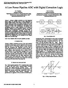
1. Introduction Most of the electronic meters designed suffer from the problem of analogue multiplication (Boghosian 1977). The digital multiplication given here is based on the quarter-square principle or the difference between two square numbers. Two DC signals (AI-Ani and Abdul-Karim 1982) that are proportional to (V Ill ) and (Jill cos ,p) are added and subtracted and then converted to a series of clock pulses with frequency proportional to the square of the sum and difference, respecti vely. A highly lineal' voltage-to-frequency converter (VFC) circuit is used in the meter design. .-\11 the analogue devices are used with the aid of an analogue computer which has highly accurate functions implementation. 2. Theory of operation 2.1. DC signal generation Taking a normal three wire AC electrical circuit (Fig. I) where the meter is connected to the transmission lines of the power system. If the input voltage and current under steady-state conditions are sinusoidal waves, the instantaneous voltage and current (Al-Ani and Abdul-Karim 1982) are given
Potential divider
Rectifier and averager
Current shunt
Squaring amplifier
Figure I.
f - - - - - - - - - - v v ' " Vm
'~
Averager
~VI oc 1m cos 4>
DC signal generator.
Received 9 January 1984; accepted 12 January 1984. t Electrical Engineering Department, College of Engineering, University of Baghdad, Iraq.
180
B. A. Haleth and M. A. H. Abdul-Karim
by v(t)= V m sin wt
(I)
i(t)=Imsin (wt±r/»
(2)
The power is (3)
where r/> is the phase angle between the voltage and current. voltage generates a DC signal V v that is proportional to V";
The rectified
Downloaded by [University of Ottawa] at 07:32 21 February 2013
where T;;. 217fw, so K VV=-f-K 1
n/w
l7W
J
0
Vmsinwtdt
therefore V=2V m K K v 1 v 17
(4)
where K; is the turn ratio of the voltage transformer and the potential divider scaling factor, K 1 is the gain constant of the first averager, and w is the angular frequency of the power lines. The current signal is controlled by the squaring voltage signal through an analogue switch. The averager (Connelly 1975) output is a DC signal proportional to 1 III cos r/> K
VI=~/v K 2
217 w
"fw
J
0
1 1ll sin (wt-r/» dt (5)
where K 2 is the gain constant of the second averager. 2.2. Square-law ADO using a VFO Figure 2 shows the square-law ADC using a VFC. The comparator output becomes zero when the integrator output reaches the input voltage level.
Integrator
Vin . . . , - - - - - - , - - - -
Figure 2. Square-law ADC.
Digital power meter
181
At the same time the V.FC produces a series of pulses with frequency proportional to the input voltage. The counting output will be
N=jt
=K V . . 3
=
111
K 3 V.
K4
ViII
K
4
2
(6)
111
Downloaded by [University of Ottawa] at 07:32 21 February 2013
whereX, is the VFC scale factor
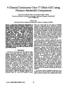
The quarter-square principle is based on the following relation for two numbers A and B: (7)
Square law "'O----1ADC and control logic
Subtroctor
Figure 3. System block diagram.
By letting A and B represent V III and /m cos 4>, respectively, as shown 'Fig. 3, the output power is
In
(8)
or (9)
Current shunt
Three wire power system a
overager
end
Rectifier
VI
Figure 4.
R
R
Digital power meter.
53
Downloaded by [University of Ottawa] at 07:32 21 February 2013
M,
p
CD
~.
~
:... 0~
::x::
:...
""'~
§
~;;:.
~
b::I
""
Digital power meter
183
~~
~
Downloaded by [University of Ottawa] at 07:32 21 February 2013
r.__ d
l 1lL----_
I. ':1