AbstractâThe focus is on direct sliding-mode control design for tracking and ... A. I. Bhatti is Faculty Member at Cen
Direct Sliding-Mode Controller Design for a 6DOF Stewart Manipulator S. Iqbal, A. I. Bhatti Abstract—The focus is on direct sliding-mode control design for tracking and regulation of a Stewart platform without any apriori knowledge of the system's mass properties in presence of nonlinearities. The position and velocities are the major inputs to the controller. The appropriately chosen sliding surface s ∈ R6, composed of system states vectors, proper choice of reachability gains drive the system to stable manifold and then slide it to an equilibrium point. It leads us to a control law which clearly deals with nominal performance and robust stability. The resulting dynamic feedback is shown to provide chatter-free control. The controller is based on generalized Lyapunov approach and guarantees global asymptotic and exponential convergence. The control performance of the proposed algorithm is verified by computer simulations. These simulations show that system follows the desired trajectory and errors efficiently converged to zero.
T
I. INTRODUCTION
HE parallel link manipulators attract many researchers in the current decade due to its precision, rigidity and high force-to-load ratio. A Stewart platform is a parallel robot provides six-degree-of-freedom i.e. roll, pitch, yaw, surge, sway and heave. Its practical usage is for disturbance isolation, precise machining and flight simulators. The Stewart manipulator consists of top-plate and baseplate connected by the help of six variable-length electromechanical actuators with spherical joints that are used for rotation and translation of the top-plate with respect to the base-plate as shown in figure 1 and 2. The angular and translation motion of the top plate with respect to the base plate is produced by reducing or extending the actuators length. The proper coordination of the actuators length enables the top plate to follow the desired trajectory with high accuracy. Thus the six inputs to the Stewart platform in term of torque are calculated by controller and provided by high speed motors. The outputs of the Stewart platform are the upper plate's angular and translation positions (in surge, sway, heave, roll, pitch and yaw) sensed by highly precise sensors. In recent years many people worked on sliding-mode for Stewart platform. Lee and Kim [1] in 1998 presented the model based sliding mode control for the Stewart platform in presence of low frequency motion of base-plate as an Manuscript received December 1, 2006. 1. S. Iqbal is a postgraduate student at Center for Advance Studies in Engineering (CASE) Islamabad Pakistan; (e-mail: siayubi@ case.edu.pk). 2. A. I. Bhatti is Faculty Member at Center for Advance Studies in Engineering (CASE) Islamabad Pakistan; (e-mail:
[email protected]).
unmodeled dynamics of the manipulator. Sliding mode controller with sliding perturbation observer is suggested [2] by Sung and Lee in 2004. A Sliding-mode control for Stewart platform, which can drive motion tracking error to zero asymptotically, has been proposed [3] in 2004 by Huang and Fu. After that same authors exhibited [4] sliding mode back stepping controller for the Stewart platform in 2005.
. . .
Figure 1: Block diagram of the Stewart platform The novelty in this paper is tracker and regulator design for the Stewart platform, its simplicity and ease of its implementation.
Figure 2: The Stewart platform In this paper we first define a hyper plane as sliding surface, and then choice of proper reachability gains, which drag the system to the sliding surface and ultimately trap the states to an equilibrium point. Afterward existence of
solution and stability analysis of closed-loop system based on generalized Lyapunov theorem is done. At the end we define a thin boundary layer in the neighborhood of the switching surface to avoid chattering and smoothing out the controller discontinuities. The rest of this paper is structured as follow, kinematics and dynamics are explained in section II. Section III deals with direct sliding-mode controller design for regulation and tracking. Simulation results are discussed in session IV. Conclusions are drawn in session V. II. KINEMATICS AND DYNAMICS The length of each actuator of Stewart platform for a given orientation can be finding out by the help of inverse kinematics [5] and can be written as:
li = Rαβγ Pi p + D − Bi
∀i = 1..6
→ (2.1)
y z α β γ]
T
q2 = M −1 ( J T u − Cq2 − G
∂ ∂ − K ( q, q ) + P (q ) = τ ∂q ∂q
τ is the applied torque. Finally get the dynamical equation of Stewart platform as:
M ( q ) q + C ( q , q ) q + G ( q ) = J T ( q )u → (2.2) Where M ∈ R6x6 is an inertial matrix; V ∈ R6x6 is
Coriolis/centripetal matrix; G ∈ R6x1 is vector containing gravity torques; J ∈ R6x6 is Jacobean matrix which changes angular velocities into Cartesian velocities and u ∈ R6x1 is vector of input signals, respectively. Some relevant properties are as below. Property 1: M( q ) is bounded function if
q and q are
bounded. V ( q , q ) is bounded function if q , q and q are bounded. G( q ) is bounded if q is bounded. Property 2: M is a symmetric and positive definite matrix for all q ∈ R. Moreover, matrix, such that
M − 2C is a skew-symmetric
xT ( M − 2C ) x = 0
→ (2.4)
06 x 6 u(t ) → (2.5) M ( q) J T ( q) we can also write the above equation as x (t ) = f ( x(t )) + g ( x(t ))u (t ) → (2.6) +
−1
y = h( x)
→ (2.7)
h( x) = [ h1 ( x) h2 ( x) h3 ( x) h4 ( x) h5 ( x) h6 ( x) ]
T
x= q q f ( x) =
∀x ∈ R n
The state-space representation of the Stewart platform dynamics can be written as
06 x 6
I6 x6 −1
06 x 6 − M (q)C (q, q )
gx
.
2. Develop the Lagrange equation as
)
)
0 I6 x6 q1 06 x1 q1 = 6 x6 + −1 −1 06 x6 −M (q)C(q, q ) q2 −M (q)G(q) q2
T
x+
06 x1 −1
− M (q)G (q)
0 6x6 M
1
q JT q
hi ( x) = I i = Rαβγ (q ) Pi p + D (q ) − Bi
1 K = K ( q , q ) = q T Mq where M ∈ R 6 x 6 2 P = P (q ) d ∂ K ( q, q dt ∂q
→ (2.3)
where
Where Rαβγ is a rotation matrix; Pi is the coordinates of top plate; D is distance vector and Bi is the coordinate of base plate respectively. The dynamic equations of the Stewart platform considering all inertial and Coriolis effects is very challenging to determine, Lebret in [6] developed the dynamic equation using Lagrange method as: 1. Calculate kinetic and potential energy as a function of
q, where q ∈ R6x1 is of the form [ x
q1 = q2
III. DIRECT SLIDING MODE CONTROL DESIGN In sliding-mode we define a hyper-plane as slidingsurface. This design approach comprises of two components; first is the reachability phase and second is sliding phase. In reachability phase states are being driven to a stable manifold by the help of appropriate control law, and in sliding phase states are then slide to an equilibrium point. One advantage of this design approach is that the effect of nonlinear terms which may be construed as a disturbance or uncertainty in the nominal plant has been completely rejected. Another benefit accruing from this situation is that the system is forced to behave as a first-order; this guarantees that no overshoot will occur when attempting to regulate the system from an arbitrary initial displacement to the equilibrium point. A. Regulator Design Let the sliding surface for Stewart platform is define as
s = Λ1q1 + q2
where
Λ1 ∈ R
6x6
→ (3.1)
is diagonal positive definite matrix and
qi ∈ R6x1 are system’s states vectors. We can write the equation (3.1) as
q2 = −Λ1q1 + s
and also
q1 = −Λ1q1 + s
→ (3.2)
The above system equation is stable if s = 0 and the rate of convergence of system is depend upon the diagonal entries of Λ matrix. The time derivative of equation (3.1) is
s = Λ1q1 + q2
M e + C e + G = J T u − M qd − C qd The state space model of the above equation is
e1 = e2
→ (3.3)
e2 = M −1 J T u − Ce2 − G − Γ
by equation (2.4) we can get as
s = Λ1q2 + M −1 ( J T u − Cq2 − G )
→ (3.4)
To evaluate stability, the candidate Lyapunov function is
V = 12 sT s
taking the time derivative of both side of equation (3.5)
V =s
Λ1q2 + M
−1
(J
T
u − Cq2 − G )
→ (3.7)
V is negative definite if 0
∀s > 0 ∀s = 0 → (3.8) ∀s < 0
stability of the system is ensured if
u = β (t ) − J −T MK d sign( s )
where
Let the sliding surface for tracking is define as
s = Λ 2 e1 + e2
→ (3.9)
β (t ) = J −T ( Cq2 + G − M Λ 1q2 )
and K d 0 , if we put the above control law then equation (3.7) becomes
V = − sT K d sign( s )
→ (3.10)
Which is always be negative definite. B. Tracking Design Let the error dynamic for Stewart platform is define as
e = q − qd
→ (3.11)
By taking the first and second derivative of equation (3.11) we get
e = q − qd
e = q − qd
where
→ (3.19)
Λ 2 ∈ R6x6 is diagonal positive definite matrix and
ei ∈ R6x1 are system’s states vectors. We can also write the
→ (3.6)
from equation (3.4) we can write equation (3.6) as T
→ (3.18)
Γ (qd , qd ) = M qd + C qd
where
→ (3.5)
V = sT s
→ (3.17)
→ (3.12)
→ (3.13)
above equation as
e2 = −Λ 2 e1 + s
and also
e1 = −Λ 2 e1 + s
→ (3.20) The above system equation is stable if s = 0 and the rate
of convergence of system is depend upon the diagonal entries of Λ 2 matrix. The time derivative of (3.19) is
s = Λ 2 e1 + e2 by equation (3.18) we get
s = Λ 2 e2 + M −1 J T u − Ce2 − G − Γ
To evaluate stability, the candidate Lyapunov function is
V = 12 sT s
→ (3.22)
taking the time derivative of both side of equation (3.22)
V = sT s
→ (3.23)
from equation (3.21) we can write equation (3.23) as
V = sT Λ 2 e2 + M −1 ( J T u − Ce2 − G − Γ ) → (3.24)
V is negative definite if Λ 2 e2 + M
−1
(J
< 0 ∀s > 0
T
u − Ce2 − G − Γ ) = = 0 ∀s = 0 → (3.25)
Also we can rewrite equation (3.11) – (3.13) as
q = e + qd
→ (3.14)
stability is ensured if
q = e + qd
→ (3.15)
where
q = e + qd
→ (3.16)
Where q d is reference signal. Put the values from (3.14) – (3.16) in the dynamical equation (2.2) of the Stewart platform, we get
→ (3.21)
u = β (t ) − J −T MK d sign( s )
> 0 ∀s < 0
→ (3.26)
β (t ) = J −T ( Ce2 + G + Γ − M Λ 2e2 )
and K d 0 , if we put the above control law then equation (3.24) becomes
V = − sT K d sign( s ) Which is always negative be definite.
→ (3.27)
-2000
2
4
-2000
6
0
2
N-m
0
0
2
4
0
2
6
4
6
Roll 2000
0 -2000
4
0 -2000
6
2000
which provide a very smooth and chatter-free control action.
6
2000
Heave
if s < δ
4 Sway
2000
-2000
s (t ) s (t ) + δ
0
0
Surge
N-m
sat ( s ) =
if s > δ
0
N-m
s (t ) s (t )
N-m
where sat ( s ) is a saturation function and can be defined as follow
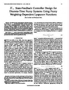
Torque Input of each Axis 2000
2000
N-m
u = β (t ) − J MK d sat ( s ) −T
However highly discontinuous control action shown in figure 5 may not be practically implementable due to hardware limitations. N-m
C. Chattering-free Controller For chattering-free controller design, instead of using (3.9) and (3.26) for regulation and tracking, we define control law as
0
2
4
0 -2000
6
0
2 Yaw
IV. SIMULATION RESULTS
Figure 5: The Sliding-mode Control Action
Simulation has been performed in-order to examine the effectiveness of proposed controller design. The platform can perform rotational and translation motion i.e. surge, sway, heave, roll pitch and yaw. Figure 3 and 4 present the simulation results of regulation and tracking controllers. Results show that the controller achieved its goal within nominal time.
An inherent discontinuities occurred in the conventional sliding mode control is reduce by using the chatter-free control. A dead band of δ =0.01 is introduced for this purpose. Figure 6 and 7 shows that by implementing a chatter-free design, performance is not much degraded and a smoother control action has been achieved as shown in figure 8.
0.5
0.5
0.4
0.4
0.3
0.3
0.2
0.2
0.1
0.1
0
0
-0.1
-0.1
-0.2
-0.2
-0.3
-0.3
-0.4 -0.5
-0.4 0
1
2
3
4
5
6
-0.5
0
Figure 3: Sliding Mode Regulation
2
3
4
5
6
Figure 6: Chatter-free Regulation
0.5
0.5
0.4
0.4
0.3
0.3
0.2
0.2
0.1
0.1
0
0
-0.1
-0.1
-0.2
-0.2
-0.3
-0.3
-0.4
-0.4
-0.5
1
0
1
2
3
4
5
Figure 4: Sliding Mode Tracking
6
-0.5
0
1
2
3
4
Figure 7: Chatter-free Tracking
5
6
N-m
200
0
2
0
0
0
0
0
0
0 − K1α − K3β + K4γ
0 −K2α + K4 β
K5γ −K4α − K5 β
K4α + K5 β 0
4
0 -500
6
0
2
6
C=
Sway
-20
N-m
N-m
4
0
2
4
0 -1000
6
0
2
Heave
2
6
4
6
K1 = cos β sin β ( I x cos2 γ + I y sin 2 γ − I z ) K2
cos 2 cos sin I x
0
K3
cos sin sin I x
K4
1 2
K5
cos sin I x
-1000
0
2
Pitch
4
6
Yaw
Figure 8: Chatter-free Control Action
A charting-free direct sliding-mode controller design approach is employed successfully for the regulation and tracking of a multi-input multi-output Stewart platform in presence of nonlinearities and time-varying uncertainties. Stability analysis based on generalized Lyapunov theory is performed to guarantee global, asymptotic and exponential convergence. In contrast to heuristic based PID tuning methods, sliding-mode design method performs better in terms of bandwidth, disturbance rejection and axes decoupling. APPENDIX Here we explore each component of the Stewart platform dynamic equation. The inertial matrix M can be written as:
m 0 0
0
0
0
0 m 0
0
0
0
0 0 m
0
0
0
cos
0 0 0 M64 I x cos
2
M 45
Ix
M 46
I z sin
M 54
M45
M 55
I x sin2
cos
2
I y cos
2
sin
sin
Ix
Iy
Iy
p
p
p
p
p
p
p
p
p
J
p
p
p
p
p
p
p
p
p
u T3x u T3y u T3z u T3 R1 P 3 u T3 R2 P 3 u T3 R3 P 3 u T4x u T4y u T4z u T4 R1 P 4 u T4 R2 P 4 u T4 R3 P 4 u T5x u T5y u T5z u T5 R1 P 5 u T5 R2 P 5 u T5 R3 P 5 u T6x u T6y u T6z u T6 R1 P 6 u T6 R2 P 6 u T6 R3 P 6
where
ui =
Rαβγ Pi p + D − Bi Rαβγ Pi p + D − Bi
1 R
0
2
I z sin
R
R
0
0 cos
sin
0 sin
cos
cos
I y cos cos sin
I y cos 2
cos
Rα = RX (α ), Rβ = RY ( β ), Rγ = RZ (γ )
M66 2
sin
u T2x u T2y u T2z u T2 R1 P 2 u T2 R2 P 2 u T2 R3 P 2
0
0
Iy
u T1x u T1y u T1z u T1 R1 P 1 u T1 R2 P 1 u T1 R3 P 1
0 0 0 M44 M45 M46 0 0 0 M54 M55
cos
Iy
where Ii represent the moment-of-inertia of the payload. Moreover, the Jacobean matrix J can be derived as:
V. CONCLUSION
M
K1α + K4γ K2α − K4 β
1000 N-m
0
0
4 Roll
500
0 0 0 0 0 0 0 −K1β − K2γ 0 0 0 0 0 0
1000
-40
N-m
Iz
0 0 0
Surge
M 44
M 66
The Coriolis and centrifugal matrix C can be written as: 0 0 0
0
-500
M46
Torque Input of each Axis 500
0 -200
M 64
N-m
In summary the controller with chatter-free design proves superior as compared to conventional sliding-mode controller in term of nominal performance and control action.
0 sin
0
1
0
sin
0 cos
cos
sin
0
sin
cos
0
0
0
1
[13] C.C. Nguyen, S.S. Antrazi, Z.L. Zhou, and C.E. Campbell, ” Adaptive Control of a Stewart Platform Based Manipulator,” Journal of Robotic Systems, vol.10, No. 5, pp.657-687, 1993. [14] S. Raghavan and J. K. Hedrick, "Observer design for a class of nonlinear systems", International Journal of Control, Vol. 59, pp 515528, 1994. [15] R.Nair,J.H.Maddocks, ”On the Forward Kinematics of Parallel Manipulators”, International Journal of Robotics Research, Vol. 13,No.2,April 1994, pp 171-188 [16] Advani, S.K., “The Kinematic Design of Flight Simulator MotionBases”, Ph.D. Thesis, Delft University of Technology. Delft University Press, 1998. ISBN 90-407-1672-2. [17] K. Liu, M. Fitzgerald, D. Dawson and F. L. Lewis, "Modeling and control of a Stewart Platform manipulator", Proc. of the Symp. of Control of Systems with Inexact Dynamic Models, Atlanta, GA,1991, pp 83-89 [18] K. Liu, F. L. Lewis, G. Lebret and D. Taylor, "The singularties and dynamics of a Stewart Platform manipulator", J. of Intelligent & Robotics Systems
0 0 0 Si
0 0
1
0 1 0 0 0 1 Sj
0 0 0 1 0 0 0
Sk
1 0
1 0 0 0 0 0
.
ACKNOWLEDGMENT The authors would like to thank Mr. Saif Ullah, Head Modeling & Simulation Division NESCOM for his assistance in simulation of the Stewart platform. The authors would also like to thank the Higher Education Commission (HEC), Pakistan for the financial support of our work. REFERENCES [1]
Nag-In Kim and Chong-Won Lee, "High Speed Tracking Control of Stewart Platform Manipulator via Enhanced Sliding Mode Control", proceeding of the 1998 IEEE International Conference on Robotics & Automation. May 1998. [2] Ki Sung You, Min Cheo Lee, kwon Son and Wan Suk You, "Sliding Mode Controller with Sliding Perturbation Observer Based on Gain Optimization Using Genetic Algorithm," proceeding of the 2004 American Control Conference Boston, 2004. [3] Chin-I Huang, Chih-Fu Chang, Ming-Yi Yu, and Li-Chen Fu, "Sliding Mode Tracking Control of the Stewart Platform", proceeding 5th Asian Control Conference. 2004. [4] Chin-I Huang, Li-Chen Fu "Smooth Sliding Mode Tracking Control of the Stewart Platform", Proceeding of the 2005 IEEE Conference on Control Applications Toronto, Canada, 2005. [5] C.C. Nguyen and F.J. Pooran, ”Dynamic Analysis of 6 DOF CKCM Robot End-Effector for Dual Arm Telerobot Systems,” Journal of Robotics and Autonomous Systems, Vol. 5,pp. 377-394, 1989. [6] G. Lebret, K. Liu and F. L. Lewis, "Dynamics Analysis and Control of a Stewart Platform manipulator", J. of Robotics Systems, 10(5), 629655(1993). [7] C.C. Nguyen, F.J. Pooran, and T. Premack, ”Control of Robot Manipulator Compliance,” in Recent Trends in Robotics:Modeling, Control and Education, M.Jamshidi, J.Y. S. Luh, and M. Shahinpoor, Eds., North Holland, NY, pp. 237-242, 1986. [8] E. F. Fitcher, "A stewart platform-based manipulator:General Theory and practical construction", International Journal of Robotics Research, pp 157-182, 1986. [9] R. Ortega, and M.W. Spong, ”Adaptive Motion Control of Rigid Robots: A Tutorial,”, Automatica, Vol.25, pp.877-588, 1989. [10] D. M. Dawson, Z. QU, F.L. Lewis, and J.F. Dorsey, ”Robust Control for the Tracking of Robot Motion”, International Journal of Control, Vol. 52, No. 3, pp 581-595 1990 [11] J.P Merlet, "Direct Kinematics and assembly modes of parallel manipulators", International Journal of Robotics Research, Vol. 11, pp 150-162, 1992. [12] Y. H. Chen and G. Leitmann, "Robustness of uncertain system in the absence of matching assumptoins", International Journal of Control, Vol. 45, pp 1527-1542, 1993.


![[PDF] Fuzzy Controller Design - Google Sites](https://m.moam.info/img/260x300/pdf-fuzzy-controller-design-google-sites_64778b03097c474c228c24b0.jpg)