621.314.572 621.313.33 621.3.016.1-52
Giuseppe BUJA Marian P. KAŹMIERKOWSKI
DIRECT TORQUE CONTROL METHODS FOR VOLTAGE SOURCE INVERTER-FED INDUCTION MOTORS − A REVIEW
SUMMARY This paper presents a review of recently used direct torque and flux control (DTC) techniques for voltage source inverter-fed induction motors. A variety of techniques, different in concept, are described as follows: switching table (ST) based hysteresis DTC, direct self control (DSC), constant switching frequency DTC with space vector modulation (DTC-SVM). Also, nowadays trends in the DTC-SVM techniques based on neuro fuzzy logic controllers are presented. Some oscillograms that illustrate properties of the presented techniques are shown.
Prof. Giuseppe BUJA Department of Electrical Engineering University of Padova
[email protected] Prof. Marian P. KAŹMIERKOWSKI Department of Electric Machine Tool Drives Electrotechnical Institute
[email protected] PRACE INSTYTUTU ELEKTROTECHNIKI, zeszyt 218, 2003
32
G. Buja, M. P. Kaźmierkowski
1. INTRODUCTION The induction motor thanks to is well-known advantages as simply construction, reliability, ruggedness and low cost has found very wide industrial applications. Furthermore, in contrast to the commutation dc motor, it can be used in aggressive or volatile environments since there are no problems with spark and corrosion. These advantages, however, are superseded by control problems when using induction motor in industrial drives with high performance demands. Based on commonly adopted complex spacevector description (represented in a coordinate system K rotating with angular speed ω K and written in per-unit form) [8, 10, 33, 37, 67-69]:
dψ sK + jω K ψ sK dt
(1)
dψ rK + j (ω K − ωm ) ψ rK dt
(2)
u sK ψ = rs i sK + TN 0 = rr i sK + TN
ψ sK = l s i sK + l M i rK
(3)
ψ rK = l r i rK + l M i sK
(4)
[ (
dωm 1 = Im ψ ∗sK i sK − mL dt TM
)
]
(5)
The induction motor control methods can be divided into scalar and vector control. In scalar control, which is based on relations valid for steady states, only magnitude and frequency (angular seed) of voltage, current and fluxl linkage space vectors are controlled. Thus, the control system does not act on space vector position during transients. Contrarily, in vector control, which is based on relations valid for dynamic states, not only magnitude and frequency (angular speed) but also instantaneous positions of voltage, current and flux space vectors are controlled. Thus, the vector control acts on the positions of the space vectors and provides their correct orientation for both steady states and transients. According to above definition, vector control is a general control
Direct torque Control methods for voltage source inverter-fed induction motors …
33
philosophy that can be implemented in many different ways. The most popular control method, known as Field Oriented Control (FOC) or Vector Control, has been proposed by Hasse [25] and Blaschke [5], and gives the induction motor high performance. In this method the motor equations are (rewritten) transformed in a coordinate system that rotates in synchronism with the rotor (stator) flux vector. These new coordinates are called field coordinates. In field coordinates − under constant rotor flux amplitude – there is a linear relationship between control variables and torque. Moreover, like in a separately excited DC motor, the reference for the flux amplitude can be reduced in field weakening region in order to limit the stator voltage at high speed. Transformation of the induction motor equations in the field coordinates has a good physical basis because it corresponds to the decoupled torque production in separately excited DC motor. However, from the theoretical point of view, other types of coordinate transformations can be selected to achieve decoupling and linearization of the induction motor equations. This has originated the methods known as modern nonlinear control [6, 42, 52, 57, 64]. Marino et al.[50] have proposed a nonlinear transformation of the motor state variables so that, in the new coordinates, the speed and rotor flux amplitude are decoupled by feedback; the method is called Feedback Linearization Control(FLC) or input-output decoupling [6, 36, 58]. A similar approach, derived from a multi-scalar model of the induction motor, has been proposed by Krzemiński [42]. A method based on the variation theory and energy shaping has been investigated recently, and is called Passivity Based Control (PBC) [57]. In this case the induction motor is described in terms of the Euler – Lagrange equations expressed in generalized coordinates. When, in the mid 1980 s, it appeared that control systems would be standardized on the basis of the FOC philosophy, there appeared the innovative studies of Depenbrock [2, 18, 19] and Takahashi and Nogouchi [63], which depart from the idea of coordinate transformation and the analogy with DC motor control. These innovators propose to replace motor decoupling with bang-bang self-control, which goes together very well with on-off operation of inverter semiconductor power devices. This control strategy is commonly refereed as Direct Torque Control (DTC) and since 1985 it has been continuously developed and improved by many other researchers [see list of references]. The purpose of this paper is to gibe a short review of the available DTC techniques and to put in evidence the differences and peculiarities of each of them. It is devoted basically to the three-phase, two level inverters. However, some references are included which concern multi-level topologies [17].
34
G. Buja, M. P. Kaźmierkowski
Remark Since there is no commonly adopted terminology regarding DTC, in this paper under DTC scheme we refer to control schemes operating with closed torque and flux loop without current controllers.
2. BASIC CONCEPTS 2.1. Basic Principles
i sq
In the standard version of FOC schemes, the torque current component is used as torque control quantity. Under constant rotor flux amplitude, it
adjusts the torque directly as given by ,
me =
l lM ψ r isq = M ψ r i s sin δ lr lr
(6)
This makes the Current Controlled (CC)-PWM inverter [40] very convenient for the implementation of the FOC scheme (Fig.2a). In the case of VSI PWM-fed drives, however, not only the stator current but also the stator flux may be used as torque control quantity (Fig.2b).
me =
lM 1 ψr ψ s sin δ ψ lr σl s
(7)
Note that the stator flux is a state variable, which can be adjusted by stator voltage. From the stator voltage equation (1), for rS = 0 , we may write,
TN
dψ s = us = uv dt
(8)
where u V is the inverter output voltage vector (Fig.2) described by the following equation:
⎧(2 / 3)U dc e j (v −1)π / 3 uv = ⎨ 0 ⎩
v = 1,...,6 for v = 0,7
for
(9)
35
Direct torque Control methods for voltage source inverter-fed induction motors … (a)
(b)
β CC-PWM-VSI
β
is
δ
is
Ψr
δΨ
u s Ψs
α
IM
Ψr
Ψs
PWM-VSI
Ψr α
IM
Ψr
xM xr
xM xr me
me
Ψs
is sin δ
sin δΨ
1 σxs
Fig.1. Torque production: a) field-oriented control; b) direct torque control.
a)
b)
B
β
u3(010)
1
1
u2(110)
1 u7(111)
Udc 0
0
0
UA
UB
u1(100)
α
u0(000)
u4(011)
UC
A
u6(101) u5(001)
C Fig.2. Simplified diagram of VSI feeding an induction motor (a); and representation of the output vectors (b).
By (9), u V assumes six non-zero values (active vectors) and two zero values (zero vectors or zero states). It follows from (8) that
1 t ψs = u v dt TN ∫0
(10)
36
G. Buja, M. P. Kaźmierkowski
For six-step operation, the inverter output voltage constitutes a cyclic and symmetric sequence of active vectors, so that, in accordance with (10), the stator flux moves with constant speed along a hexagonal path (Fig.3a). The introduction of zero vectors stops the flux, an effect known as a stop pulse, but does not change its path. There is only a change of cycle and symmetry of the voltage vector sequence. This differs from sinusoidal PWM operation, where the inverter output voltage constitutes a suitable sequence of active and zero vectors and the stator flux moves along a track resembling a circle (Fig.3b). a)
b)
β
β
ψ
ψ
s
s
α
α
Fig.3. Typical stator flux path in α − β plane: a) under six-step operation; b) under sinusoidal PWM operation (low switching frequency).
In any case, the rotor flux rotates continuously with the actual synchronous speed along a near-circular path, because its components are smoothed by the rotor circuit filtering action. Stator and rotor flux vectors are related by the following equation:
ψs =
lM ψ r + σl s i s lr
(11)
From the point of view of torque production it is the relative motion of the two vectors that is important, for they form the torque angle δ ψ (Fig.1b) that determines the instantaneous motor torque according to (7). Suppose that the rotor flux ψ r moves slowly in the anticlockwise direction (Fig.5). In such a case, forward switching of the active voltage vector causes rapid movement of ψ s away from ψ r and, in the same circumstance, produces a motor torque increase because the torque angle δ ψ increases. On
Direct torque Control methods for voltage source inverter-fed induction motors …
37
the other when a zero vector is used, the stator flux vector ψ s comes to a stop that, since ψ r continues to move forward, causes a decrease in the torque angle δ ψ and then in the motor torque me . If the duration To of the zero state is sufficiently long, ψ r will overtake ψ s ; as a result, the angle δ ψ and the motor torque will change direction. The important conclusion that follows from the above analysis is that there is a direct relation between torque oscillations and the duration of zero states. By cyclic switching of active and zero states, the motor torque is controlled. This is the principle of operation of the self-controlled modulator [18].
moment with active forward vector
q
stops with zero vector + Hm
me ~ ψ sq − Hm
δΨ
moment with active backward vector
ψs
ψr d
α
rotates continuously
stator
Fig.4.Stator flux vector ψ S movement relative to rotor flux vector
ψ r under the influence of active and zero voltage vectors.
In the range of very low speeds (< 0.2ω N ) , the rotor flux ψ r motion is too slow to achieve rapid torque reduction. In such a case, an active vector moving backward is selected rather than a zero vector (Fig.5). In the field-weakening region, zero vectors cannot be employed. Torque control may then be achieved via a fast change of torque angle δ ψ by advancing (to Increase the torque) or retarding (to reduce it) the phase of the stator flux. Summing up the outcomes so far obtained, we may say that the VSI-fed induction motor is characterized by the following properties:
38
G. Buja, M. P. Kaźmierkowski
•
the inverter output voltage can only be in one of two states, either active (one of the non-zero vectors u1 ,..., u6) or zero (u 0 ,u 7 ) ;
•
the active forward vectors (states) produce field movement with constant linear speed whilst the zero vectors (states) stops the field; from the point of view of torque production, these two states correspond, respectively, to torque increase and torque increase and torque reduction conditions; the active backward vectors produce field movement with constant linear speed in the opposite direction; for six-step operation (active states only), the stator flux moves along a hexagonal path constant linear speed (υ s = u d / TN ) and an angular
• •
speed the average value of which is inversely proportional to the flux amplitude (ω s = υ s / ψ s ) ;
•
•
for sinusoidal PWM operation (active and zero states), at high switching frequency the stator flux moves along a near-circular path with nearly constant angular speed equal to the actual synchronous speed; the rotor flux always moves continuously along a circular path with the actual synchronous angular speed.
2.2. Generic DTC Scheme The generic DTC scheme for a VS-PWM inverter-fed induction motor drive is shown in Fig.5. According to the previous discussion, the scheme includes of two hysteresis controllers. Stator flux controller imposes the time duration of the active voltage vectors, which move the stator flux along the reference trajectory, and torque controller determinates the time duration of the zero voltage vectors, which keep the motor torque in the defined-by-hysteresis tolerance band. Finally, in every sampling time the voltage vector selection block chooses the inverter switching state (SA, SB, SC), which reduces the instantaneous and torque errors. Compared to the conventional FOC scheme (Fig.5b), the DTC scheme has the following features: • there is no current control loops; hence, the current is not regulated directly, • coordinate transformation is not required, • there is no separate voltage pulse width modulator, • stator flux vector and torque estimation is required.
39
Direct torque Control methods for voltage source inverter-fed induction motors …
a)
ψ sc
Flux Controller Active Vectors Voltage Vector Selection
mc
Zero Vectors
SA SB SC
VSI PWM Inverter
ψs
uA uB uC
Induction Motor
isα isβ me
Ν(γs)
Torque Controller
b)
ψ sc ~ isdc
Flux Current Controller
Coordinate Transformation
PI U sdc
Torque Current Controller mc ~ isqc
U sqc
d −q
α−β
PI
U sαc
U sβc
SA
SVM
SC
sin cos isq
isd
SB
VSI PWM Inverter
ψs
uA uB uC
Induction Motor
i sα isβ me
γs
α−β d −q
Fig.5. Basic scheme of PWM inverter-fed induction motor with: a) direct torque and stator flux control (DTC), b) field oriented control (FOC).
3. SWITCHING TABLE BASED DIRECT TORQUE CONTROL (ST-DTC) 3.1. Basic ST-DTC scheme The block diagram of the Switching Table based Direct Torque Control (ST-DTC) scheme is shown in Fig.6.
40
G. Buja, M. P. Kaźmierkowski Flux Controller
Ψ sc
Udc
dΨ dm
mc
Vector Selection Table
SA SB SC
Ν(γs)
Torque Controller me
Ψs
Sector Detection Ψ sβ Ψsα Flux and Torque estimator
Voltage Calculation us is Motor
Fig.6. Block scheme of the Switching Table Based DTC with circular stator flux path according to Takahashi and Nogouchi.
The command stator flux ψ SC and torque mC values are compared with the actual ψ S and me values in hysteresis flux and torque controllers, respectively. The flux controller is a two level comparator while the torque contollers is three level comparator. The digitized output signals of the flux controller are defined as:
dψ = 1
for
ψ s < ψ sc − H ψ
(12a)
dψ = 1
for
ψ s < ψ sc + H ψ
(12b)
and those of the torque controller as
dm = 1
for
me < mc − H m
(13a)
dm = 0
for
me = mc
(13b)
d m = −1
for
me < mc + H m
(13c)
The digitized variables dψ d m and the stator flux sector, obtained from
angular position γ s = arctg(ψ sβ / ψ sα ), create a digital word which is used as
Direct torque Control methods for voltage source inverter-fed induction motors …
41
address for accessing an EPROM, by which the appropriate voltage vector is selected according to the Switching Table 1.
TABLE 1
N(γs)
N=1
N=2
N=3
N=4
N=5
N=6
dm = 1
u2(110)
u3(010)
u4(011)
u5(001)
u6(101)
u1(100)
dm = 0
u7(111)
u0(000)
u7(111)
u0(000)
u7(111)
u0(000)
d m = −1
u6(101)
u1(100)
u2(110)
u3(010)
u4(011)
u5(001)
dm = 1
u3(010)
u4(011)
u5(001)
u6(101)
u1(100)
u2(110)
dm = 0
u0(000)
u7(111)
u0(000)
u7(111)
u0(000)
u7(111)
d m = −1
u5(001)
u6(101)
u1(100)
u2(110)
u3(010)
u4(011)
dψdm
dψ = 1
dψ = 0
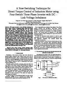
The excellent dynamic performance of torque control is evident in Fig.7, which shows torque reversal for half rated speed. Thanks to the selection of appropriate backward voltage vector, torque reversal of rated value takes place in about 1 ms, although reversal in the opposite direction depends on the inverter supply voltage reserve. The characteristic features of the ST-DTC scheme of Fig.6 include:
usβ me isβ
Fig.7. Typical transient response to rated torque of the ST-DTC scheme of Fig.6.
42
G. Buja, M. P. Kaźmierkowski
•
nearly sinusoidal stator flux and current waveforms; the harmonic content is determined by the flux and torque controller hysteresis bands H ψ and H m ,
• •
excellent torque dynamics, flux H ψ and torque H m hystereses determine the inverter switching frequency which varies with the synchronous speed and load conditions.
3.2. Modified ST - DTC Many modifications of the basic ST – DTC scheme in terms of improvement of starting, overload conditions, very low speed operation, torque ripple reduction, variable switching frequency and noise level attenuation at low speed have been proposed during last decade. 1. Improvement of starting conditions and very low speed performance During starting and very low speed operation the basic ST – DTC scheme selects many times zero voltage vectors resulting in flux level reduction owing to the stator resistance drop. This important drawback can be avoided by using a dither signal [35, 56] or a modified switching table in order to apply all the available voltage vectors in appropriate sequence [14, 16, 69]. Also, predictive technique can be used [39, 40, 43]. 2.Torque ripple reduction by increased number of generated inverter switching states Subdivision of the sampling period in two or three [14] equal time intervals leads to 12 or 56 voltage vectors, respectively (Fig.8). The increased number of available voltage vectors allows both to subdivide the hysteresis of torque and flux controllers into more levels and to create a more accurate switching table which takes into account also the speed level. 3. Rotor flux amplitude control Under constant rotor flux operation the IM torque increases linearly with the slip frequency and the maximum torque is limited only by the maximum current of the inverter. Therefore, in order to increase the torque overload capability of a ST – DTC scheme, the rotor flux instead of stator flux vector magnitude should be regulated. For given commands of rotor flux ψ rc and torque mc , the stator flux command needed by a ST – DTC scheme can be calculated as [15]:
43
Direct torque Control methods for voltage source inverter-fed induction motors … 2
⎛l ⎞ m ⎞ 2⎛ l ψ sc = ⎜⎜ s ψ rc ⎟⎟ + (σl s ) ⎜⎜ r c ⎟⎟ ⎝ lM ⎠ ⎝ l M ψ rc ⎠
2
(14)
However, the price for better overload capabilities is higher parameter sensivity of rotor flux amplitude control. a)
b) sector 4 sector 5
u4u
β
sector 3
u4
u3
β sector 2
5
u2 sector 6
u6
sector 1+
sector 1 u1
u7 sector 7
α
α
u12 sector 12 u8
sector 8
u11 u9 sector 9
u10
sector 1-
sector 12
sector 10
Fig.8. Voltage vectors generated with two (a) and three (b) equal time intervals per cycle period.
4. DIRECT SELF CONTROL SCHEME (DSC) 4.1. Basic DSC scheme The block diagram of Direct Self Control (DSC) scheme, proposed by Depenbrock [18], is shown in Fig.9. Based on stator flux components ψ βA , ψ βB , ψ βC , the flux comparators generate the digitized variables d A , d B , d C , which correspond to active voltage vectors for six step operation. The hysteresis torque controller, on the other
44
G. Buja, M. P. Kaźmierkowski
hand, generates the digitized signal d 0 which determines the zero states duration. Thus, in the constant flux region, the control algorithm is as follows:
d 0 = 1 → S A = d B , S B = d C , S C = d A , i.e. an active voltage vector is selected, defined by the flux comparators;
d 0 = 0 → S A = 0, S B = 0, S C = 00, or S A = 1, S B = 1, S C = 1, i.e. a zero voltage vector is selected.
Flux Comparators
Ψ sc
Udc
dB
ΔΨ s
SA
dA
PI
SC SB
mc
dο dC
Torque Controller
Voltage Calculation Ψ sA Ψ sB
Ψ sC
ABC
α β
Ψ sα us Ψ sβ Flux and Torque me estimator
is
Motor
Fig.9. Block scheme of the DSC with hexagonal stator flux path according to Depenbrock.
In the field weakening region, where the inverter is in sixstep operation under rated output voltage, the torque is not determined by the torque controller but by a change of the stator flux amplitude Δψ s . In a simple case, this can be implemented with the help of the PI-flux controller of Fig.9. However, for precise control, more complex calculation is required [49, 61]. The dynamic performance of the torque control in the DSC scheme is scheme is shown in Fig.11. In the basic version, DSC during torque reversal selects zero instead of backward voltage vector [18]. The characteristic features of the DSC scheme of Fig.9. are:
Direct torque Control methods for voltage source inverter-fed induction motors …
• •
• • •
•
45
the possibility of PWM operation in the constant flux region and six-step operation with constant voltage in the field weakening region; non-sinusoidal stator flux and current waveforms that, with the exception of the harmonics, are identical for both PWM and six-step operation; the stator flux vector moves along a hexagon path also for PWM operation; no supply reserve is necessary and the inverter capability is fully utilized; the inverter switching frequency is lower than in TB-DTC scheme of Fig.6 because PWM is not of sinusoidal type as it turns out by comparing the voltage pattern in Fig.7 and 9; excellent torque dynamics in constant and weakening field regions.
usβ me isβ
Fig.10. Typical transient response to rated torque reversal of the DSC scheme of Fig.9.
Note that the behavior of a DSC scheme can be reproduced by a ST-DTC scheme when the hysteresis band of the stator flux comparator is set to: H ψ = 0.076 ψ sc [11]. Low switching frequency and fast torque control even in the field weakening region are main reasons why the DSC scheme is convenient for high power traction drives [62, 70, 71].
46
G. Buja, M. P. Kaźmierkowski
4.2. Indirect Self Control - ISC In contrast to DTC – which, since the publication of the I. Takahashi and T. Nogouchi paper [63], have been constantly developed and improved by many researchers and research centers – DSC has been studied and developed mainly by the Power Electronics Group of the Ruhr University at Bochum, Germany, led by M. Depenbrock and A. Steimel [2, 26, 27, 29, 30, 38, 61]. To improve The DSC performance at low speed region, the method called Indirect Self Control (ISC) has been proposed [29]. In the first stage of development, this method was used in DSC drives only for starting and for operation up to 20-30% of rated speed [30]. Later it has been expanded as a new control strategy offered for inverters operated at high switching frequencies (>2 kHz) [27]. The ISC scheme, however, operates under circular stator flux path in association with a voltage pulse width modulator and, therefore, will be presented in the next Section.
5. CONSTANT SWITCHING FREQUENCY DTC SCHEMES 5.1. Critical Evaluation of Hysteresis-based DTC Schemes The well-known disadvantages of the hysteresis based DTC schemes are: variable switching frequency, violence of polarity consistency rules (to avoid ± 1 switching over DC link voltage), current and torque distortion caused by sector changes, starting and low speed operation problems as well as high sampling frequency needed for digital implementation of hysteresis controllers. When the hysteresis controller is implemented in a digital signal processor (DSP), its operation is quite different from that of the analog scheme. Fig.11 illustrates a typical switching sequence in (a) analog and (b) discrete (also called sampled hysteresis) implementation. For instance, in analog implementation the torque ripple would be kept exactly within the hysteresis band and the switching instants are not equally spaced. In contrast, the discrete system operates at fixed sampling time Ts and the hysteresis controller is effctive only if
Direct torque Control methods for voltage source inverter-fed induction motors …
H m >>
dmmax ⋅ Ts dt
47
(15)
otherwise not the hysteresis band but the sampling frequency decides the switching instant. All the above difficulties can be eliminated when, instead of the switching table, a voltage pulse width modulator is applied.
a)
b) (a)
(b)
S/H 1/Ts
mc + H m mc mc - Hm
t1
t2
t3
Ts
Ts
Ts
Fig.11. Operation of the analog (a) and discrete (b) hysteresis controller.
Basically, the DTC strategies operating at constant switching frequency can be implemented by means of closed-loop PI, predictive/dead-beat or neurofuzzy controllers. These controllers calculate the required stator voltage vector, averaged over a sampling period. The voltage vector is finally synthesized by a PWM block, which in most cases is the Space Vector Modulation (SVM). So, contrary to conventional DTC, in a DTC-SVM scheme the switching harmonics are neglected in the control algorithm.
5.2. DTC Scheme with Closed-Loop Flux Control In DTC-SVM scheme of Fig.12a), the stator flux components in the rotor flux coordinates ψ sdc , ψ sqc are calculated from the commanded values of torque
mc and rotor flux magnitude ψ rc according to the following equations:
ψ sdc =
ls ⎛ dψ rc ⎞ ⎜1 + σTr ⎟ lM ⎝ dt ⎠
(16a)
48
G. Buja, M. P. Kaźmierkowski
ψ sqc =
ls m σ ls c lM ψ rc
(16b)
The command value of the stator flux vector ψ sc , after coordinate transformation dq / αβ , is compared with the estimated value ψ s and the error Δψ s , together with the stator resistance drop, allows to calculate the appropriate stator voltage vector u sc which is applied to IM in the next sampling period:
u sc =
TN Δψ s + rs ⋅ i s Ts
(17)
As it was mentioned in Section III.B.3, the use of rotor instead of stator flux magnitude improves the torque overload capabilities of IM.
5.3. DTC-SVM Scheme with Closed-Loop Torque Control The DTC-SVM scheme of Fig.12a) requires stator and rotor flux vector estimators and, therefore, all IM parameters has to be known. To enhance the dynamic and steady-state performance of the torque response a variant of the scheme with closed-loop torque control can be used (Fig.12b)) [75]. In this scheme the torque controller generates the command value of the torque angle increment Δδ ψ , which is added to the commanded stator flux magnitude ψ sc to calculate the stator flux vector command ψ sc according to:
ψ sc = ψ sc e j (rs + Δδ Ψ )
(18)
where γ s is the rotor flux vector position in the stator reference frame α , β . The commanded stator flux vector ψ sc is compared with the estimated one ψ s and the resultant error Δψ s is used for calculation of the commanded stator voltage vector according to (17).
Direct torque Control methods for voltage source inverter-fed induction motors …
49
a) ψ rc mc
ψ sdc Eqs (16)
SA
d −q
Ψsqc
Δ ψ s TN
ψsc
usc
α−β
SC
ψs
γ sr Rotor Flux Estimator
SB
SVM
TS
rs Voltage Udc Calculation
us
Stator Flux Estimator
iA
α −β
is
iB
ABC
b) ψ sc Torque Controller mc
SA
ΔδΨ
PI
Eqs (16)
m
ψsc
Δψs
u sc
TN TS
SC
ψs
γs
SB
SVM
rs Flux and Torque Estimator
Voltage Udc Calculation
us
iA
α −β
is
iB
ABC
c) ψ sc
mc
Flux Controller
kΨ
P PI
Δγ sd
SA
Δγ s
Eqs (21)
Δψ s
usc
TN TS
SC
rs
Δγ ss
Torque Controller
SB
SVM
Ψs
Flux and Torque Estimator
m
us
is
Voltage Udc Calculation
iA
α −β
iB
ABC
d) ψ sc
mc
Flux Controller u sdc
PI PI
u sc
SB
SVM
SC
α −β
usqc
Torque Controller
SA
d −q
γs ψs m
Flux and Torque Estimator
us
is
Voltage Udc Calculation
α −β ABC
iA iB
Fig.12. Basic variants of DTC-SVM scheme; a) DTC-SVM with closed-loop flux control [15], b) DTC-SVM scheme with closed-loop torque control [75], c) DTC-SVM scheme operating in polar coordinate – ISC [29, 30], d) DTC-SVM scheme operating in Cartesian coordinates – Stator Flux Oriented Voltage Control [1, 74].
50
G. Buja, M. P. Kaźmierkowski
1.0 0.8
me
usβ
0.6 0.4 0.2
i sβ
0.0 -0.2 -0.4 -0.6 -0.8 -1.0
Fig.13. Transient response to rated torque reversal of the DTC-SVM scheme in Fig.12(d).
5.4. DTC-SVM Scheme with Closed-Loop Torque and Flux Control Operating in Polar Coordinates – Indirect Self Control Further improvement can be achieved when both torque and stator flux magnitude are controlled in closed-loop way. The version operating in polar coordinates is shown in Fig.12c) [29, 30]. In this scheme the error of the stator flux vector Δψ s is calculated from the outputs of the flux k ψ and torque
Δγ s controllers as follows:
{
}
Δψ s (k ) = ψ s (k ) − ψ s (k − 1) = [1 + k ψ (k )]⋅ e jΔγ s (k ) − 1 ⋅ ψ s (k − 1)
(19)
With the approximation
e jΔγ s (k ) ≅ 1 + jΔγ s (k ) (19) can be written in the form:
(20)
Direct torque Control methods for voltage source inverter-fed induction motors …
Δψ s = [k ψ (k ) + jΔγ s (k )]⋅ ψ s (k − 1)
51 (21)
The last equation is used to calculate the commanded stator voltage vector according to (17). To improve the dynamic performance of the torque control, the angle increment Δγ s is composed of two parts: the dynamic part Δγ sd delivered by the torque controller and the stationary part Δγ ss generated by a feedforward loop.
5.5. DTC-SVM Scheme with Closed-Loop Torque and Flux Control Operating in Cartesian Coordinates– Stator Flux Oriented Control The outputs of the PI flux and torque controllers can be interpreted as the d-q stator voltage components u sdc in stator flux oriented coordinates giving the block scheme in Fig.12d) [88]. The control strategy relies on a simplified description of the stator voltage components, expressed in stator flux oriented coordinates as:
u sd = rs ⋅ isd +
dψ sc dψ sc ≈ dt dt
u sq = rs ⋅ i sq + ω s ψ sc = k s mc + ω s ψ sc
(22a) (22b)
where k s == rs / ψ sc . The above equations show that the component u sd has influence only on the change of stator flux magnitude, and the component u sq - if the term ω s ψ s is decoupled – can be used for torque adjustment. So, after coordinate transformation dq / αβ into the stator-oriented frame, the command values u sαc u sβc are delivered to SVM. Note that calculation of the commanded stator voltage vector by (22) requires the derivative of the stator flux magnitude, which is a dc quantity. Then the scheme of Fig.12d) is less noisy than the previously presented schemes of Fig.12a)-c) that are based on (17). Also, combined DTC/DTC-SVM solutions have been proposed [37, 43], where the conventional ST-DTC scheme operates only in dynamic states.
52
G. Buja, M. P. Kaźmierkowski
5.6. Dead-Beat DTC-SVM Schemes The main idea of a dead-beat DTC controller is to force torque and stator flux magnitude to achieve their reference values in one sampling period by applying a suitable stator voltage vector generated by SVM. In the approach proposed by T.G. Habetler et al [23, 24], the changes of torque and flux over one sampling period are at first predicted from motor equations, and then a quadratic equation is solved to obtain the command value of stator voltage vector in stator oriented coordinates. This time consuming algorithm is used in steady states. During transients, an alternative algorithm is used and the appropriate voltage vector is selected a priori from a switching table, which includes only active vectors. This guarantees fast elimination of transient errors. Due to limitation of inverter voltages and currents, dead-beat control is not always possible. Based on a discrete model of IM, J.Maes and J.Melkebeek [48] have proposed an algorithm – called Direct Time DTC – which uses a prediction of the back EMF. The DTC algorithm also incorporates limitation of inverter voltage and current as well as compensation of calculation delay. Another interesting approach based on a dead-beat digital controller applied instead of PI controllers in the DTC-SVM scheme of Fig.12d) has been developed by J.H. Lee et al. [44]. In the paper the z-domain design of the transfer function G R ( z ) of the flux and torque controllers is carried out starting from the desired closed-loop transfer function F ( z ) :
G R (z ) =
F (z ) G s ( z )[1 − F ( z )]
(23)
where G s ( z ) is the open-loop transfer function. The DTC-SVM scheme of Fig.12d) with torque and flux controllers determined according to this method exhibits good steady-state and dynamic performance even for low switching frequency (0.5 – 2 kHz). Therefore, it can be used in high-performance high-power drives (traction applications).
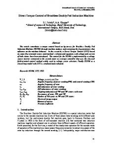
5.7. Neuro-Fuzzy DTCSVM Scheme In the last decade a fast development of artificial intelligence-based controllers has been observed. They have expanded also in the area of power electronics and drive control [10, 37, 68]. The combination of fuzzy logic and
Direct torque Control methods for voltage source inverter-fed induction motors …
53
artificial neural networks has been proved to be powerful as it offers all the adfvantages of both techniques. The initial structure of the controllers is commonly built up using the human expert knowledge [13, 37, 51-53, 68]. A controller based on Adaptive Neuro-Fuzzy Inference System (ANFIS) for voltage space vector generation has been proposed by P.Z. Grabowski et al. [21]. It combines fuzzy logic and artificial neural networks for decoupled flux and torque control. In The scheme, shown in Fig. 14(a), the error signals ε ψ and ε m are delivered to the Neuro-Fuzzy (NF) controller, which is also entered by the actual position (γ s ) of the stator flux vector. The NF controller determinates the stator voltage command vector in polar coordinates v c = [Vc , ϕVc ] for the SVM block. The scheme is characterized by simple self-tuning procedure and good steady-state and dynamic performance (Fig.14 b). a) 1Layer
2 Layer
min
min
min min min
wm
w 62
w 72 w 82 min w 92
εm
min
min
membership function tuning
o1 o2
w 22 w 32 w 42 w 52
5 Layer
U dc
w 12
o3
Normalization
εΨ
min
wΨ
3 Layer 4 Layer
o4 o5 o6
Δγi Table Vector Adder
V sc ϕ Vc
o7 o8 o9
γs
o5 weight tuning
b) 5 0 m s /d iv
Ψ s (1 W b /d iv )
i s α ( 1 0 A /d i v )
m e (1 0 N m /d iv )
m c (1 0 N m /d iv )
Fig.14. Neuro-Fuzzy DTC-SVM: a) block scheme, b) experimental oscillogram illustrating torque tracking performance.
54
G. Buja, M. P. Kaźmierkowski
6. CONCLUSIONS This paper has reviewed Direct Torque Control (DTC) strategies for PWM inverter-fed AC motor drives. The DTC represents a viable alternative to Field Oriented Control (FOC) being also a general philosophy for controlling the AC drives in both motor and generator mode of operation. From a general perspective, FOC requires an accurate estimation of the rotor flux vector. Once such estimation is done (whether for the rotor or the stator flux vector), there is no need to set up a current control loop and DTC is the natural solution. The main features of DTC can be summarized as follows: • According to adopted definition, DTC operates with closed torque and flux loops but without current controllers, • DTC needs stator flux and torque estimation and, therefore, is not sensitive to rotor parameters, • DTC is inherently a motion sensorless control method, • DTC has simple and robust control structure; however, the performance of DTC strongly depends on the quality of the actual stator flux and torque and, for motion sensorless schemes, on the speed/position observers. Strating from the IM drives, the DTC strategies have been divided into three groups: hysteresis-based switching table (ST) DTC, hysteresis-based direct self control (DSC) and constant switching frequency schemes operating in association with space vector modulators (DTC-SVM). The basic principles and the latest developments of these strategies have been systematically presented. Their advantages and limitations have been briefly examined and the application fields have been indicated. DSC is preferred for high-power low-switching frequency drives and is very effective in square-wave operation region where fast flux weakening and torque control can be achieved. Therefore, it is well suited for traction and vehicle drives. Constant switching frequency DTC-SVM schemes improve considerably the drive performance in terms reduced torque and flux pulsations, reliable start up and low speed operation, well-defined harmonic spectrum as well as radiated noise. Therefore, DTC-SVM is an excellent solution for generalpurpose IM drives in a very wide power range. Intead, the short sampling time required by the ST-DTC schemes makes them suited to very fast torque and flux controlled drives in spite of the simplicity
Direct torque Control methods for voltage source inverter-fed induction motors …
55
of the control algorithm. As a conclusion of the survey, it is believed that the DTC principle will continue to play a strategic role in the development of highperformance motion sensorless AC drives.
LITERATURE 1.
Baader U.: “High Dynamic Torque Control of Induction Motor in stator Flux Oriented Coordinates” (in German), etz Archiv, Vol.11, No 1, pp. 11-17, 1998.
2.
Baader U., Depenbrock M., Gierse G.: „Direct Self Control (DSC) of Inverter-FedInduction Machine – A Basis for Speed Control Without Speed Measurement“, IEEE Trans. Of Industry Applications, Vol.28, No.3 May/June, pp.581-588, 1992.
3.
Bertoluzzo M., Buja G., Menis R.: „Analytical formulation of the direct control of induction motor drives”, in Proc. Of IEEE International Symposium on Industrial Electronics, pp.1420, 1999.
4.
Bertoluzzo M., Buja G., Menis R.: „Operation of DFTC IM drives under estimation process errors”, in Proc. Of International Conference on Power Electronics and Motion Control, pp.1.27-1.34, 2000.
5.
Blaschke F.: “The principle of field-orientation as applied to the Transvector closed-loop control system for rotating-field machines”, in Simens Reviev 34, pp.217-220, 1972.
6.
Bodson M., Chiasson J., Novotnak R.: “High performance induction motor control via input-output linearization”, IEEE Control Systems, pp.25-33, August 1994.
7.
Boldea I., Nasar S.A.: “Torque vector control. A class of fast and robust torque, speed and position digital controllers for electric drives”, Electromechanical and Power System, Vol.15, pp.135-147, 1988.
8.
Boldea I., Nasar S.A.: Electric Drives, CRC Press, Boca Raton-Ann Arbor-London-Tokyo, 1999.
9.
Bonanno F., Consoli A., Raciti A., Testa A.: “ An Innovative Direct Self-Control Scheme for Induction Motor Drives”, IEEE Trans. On Power Electronics, vol. PE-12, September, 1997.
10.
Bose B.K.: Modern Power Electronics and AC Drives, Englewood Cliffs, Prentice-Hall, 2001.
11.
Buja G., Casadei D., Serra G.: „DTC-Based Strategies for Induction Motor Drives”, in Proc.of the IEEE-IECON Conf., Vol.4, pp.1506-1516, 1997.
12.
Buja G.: “A New Control Strategy of the Induction Motor Drives: The Direct Flux And Torque Control”, IEEE Industrial Electronics Newsletter, Vol.45, No.4, Dec., pp.14-16, 1998.
13.
Cabrera L.A., Elbuluk M.E., Zinger D.S.: “Learning Techniques to Train Neural Networks as a State Selector for Inverter-Fed Induction Machines Using Direct Torque Control”, in IEEE Trans. On Power Electronics, Vol.12, no.5, September, pp.788-799, 1997.
14.
Casadei D., Profumo F., Serra G., Tani A.: “FOC and DTC: Two Viable Schemes for Induction Motors Torque Control”, IEEE Trans.on Power Electronics, Vol.17, No.5, pp.779-787, 2002.
15.
Casadei D., Serra G., Tani A.: „Constant frequency operation of a DTC induction motor drive for electric vehicle“, in Proc. Of ICEM Conf., 1996, Vol.3, pp.224-229.
56
G. Buja, M. P. Kaźmierkowski
16. Casadei D., Serra G., Tani A., „Analytical Investigation of Torque and Flux Ripple in DTC Schemes for Induction Motors“ in Proc. of the IEEE-IECON Conf., 1997, pp.552-556. 17. Cascone V., Mantica L., Oberti M.,:“Three level inverter DSC control strategy for traction drives”, in Proc. of 5 rd European Conf. On Power Electronics and Applications, Firenze, Vol.1., 1989, pp.135-139. 18. Depenbrock M.: “Direct Self Control of Inverter-Fed Induction Machines”, IEEE Trans. on Power Electronics, Vol.PE-3, no.4, pp.420-429,Oct.1988. 19. Depenbrock M.: “Direct self-control of the flux and rotary moment of a rotary-field machine”, U.S. Patent 4, 678, 248. 20. “Direct Torque Control-the world’s most advanced AC drive technology”. Technical Guide, no.1. ABB Finland. 21. Grabowski P.Z., Kaźmierkowski M.P., Bose B.K., Blaabjerg F.:” A Simple Direct-Torque Neuro-Fuzzy Control of PWM-Inverter-Fed Induction Motor Drive”, IEEE Trans. On Industrial Electronics, Vol. 47, no.4, pp.863-870,2000. 22. Habetler T.G., Divan D.D.: “Control Strategies for Direct Torque Control Using Discrete Pulse Modulation”, IEEE Trans. On Industry Applications, Vol.27, no.5, Sept./Oct., pp.893901, 1991. 23. Habetler T.G., Profumo F., Pastorelli M.: “Direct Torque Control of Induction Machines Over a Wide Speed Range”, in XXX, pp.600-606, 1992. 24. Habetler T.G., Profumo F., Pastorelli M., Tolbert L.M.: „Direct Torque Control of Induction Motor Using Space Vector Modulation“, in IEEE Trans. On Indusstry Applications, Vol.28, no.5, Sept./Oct., pp.1045-1053, 1992. 25. Hasse K.: “Drehzahlgelverfahren fur schnelle Umkehrantriebe mit stromrichtergespeisten Asynchron-Kurzchlusslaufer-motoren”, Reglungstechnik, Vol. 20, pp.60-66, 1972. 26. Hoffman F.: „Drehgeberlose geregelte Induktionmaschinen an IGBT-Pulsstromrichtern“, Dissertation Ruhr-Universiät Bochum, VDI-Verlag Reihe 21: Elektrotechnik, No .213, Düsseeldorf 1996. 27. Hoffman F., Janecke M.: „Fast Torque Control of an IGBT-Inverter-Fed Tree-Phase A.C.Drive in the Whole Speed Range-Experimental Result“, in Proc.EPE Conf., pp.3.3993.404, 1995,. 28. Idris N.R.N., Yatim A.H.: “Reduced torque ripple and constant torque switching frequency strategy for induction motors”, in Rec. of IEEE Applied Power Electronics Conference, pp.154-161, 2000. 29. Jänecke M.: ”Die Direkte Selbstregelung bei Anwendung im Traktionsbereich”, Dissertation Ruhr-Universität Bochum, VDI-Verlag, Reihe 8: Mess-, Steuerungs- und Regelungstechnik, No.282, Düsseldorf 1991. 30. Janecke M., Kremer R., Steuerwald G.: „Direct self-control, a novel method of controlling asynchronous machines in traction applications“, in Proc. Of 3rd EPE’89 Conf., Aachen, Vol.1., pp.75-81, 1989,. 31. Jonsson R.: “Method and apparatus for controlling an AC induction motor”, U.S.Patent 5, 294, 876. 32. Jonsson R., Leonhard W.: “Control of an Induction Motor without a Mechanical Sensor, based on the Principle of “Natural Field Orientation” (NFO)”, in Proc. Of IPEC Conference, Yokohama, Japan, 1995. 33. Kaźmierkowski M.P., Tunia H.: Automatic Control of Converter Fed Drives, ELSEVIER Amsterdam-London-New York-Tokyo, 1994.
Direct torque Control methods for voltage source inverter-fed induction motors …
57
34. Kaźmierkowski M.P., Orłowska-Kowalska T.: „ANN Based Estimation and Control in Converter-Fed Motor Drives”, In: Soft Computing in Industrial Electronics, Osaka S.J. and Sztandera L. (Eds), Physica Verlag Heidelberg, Germany, pp.45-94. 35. Kaźmierkowski M.P., Kasprowicz A.: „Improwed Direct Torque and Flux Vector Control of PWM Inverter-Fed Induction Motor Drives”, in IEEE Trans. Of Industrial Electronics, Vol.42, no.4, pp.344-350, Aug.1995. 36. Kaźmierkowski M.P., Sobczuk D.L.: „Sliding Mode Feedback Linearized Control of PWM Inverter-Fed Induction Motor” in Proc.IEEE/IEC’96, Taipei, pp.244-249, 1996. 37. Kaźmierkowski M.P., Krishnan R., Blaabjerg F.: Control in Power Electronics, Academic Press, 2002. 38. Koch S.: “Beiträge zur Regelung von Induktionsmachinen ohne Drehgeber“, Dissertation Ruhr-Universität Bochum, VDI-Verlag Reihe 8: Mess-, Steuerungs- und Regelungstechnik, No.717, Düsseldorf 1998. 39. Kang J.K., Sul S.K.: „New Direct Torque Control of Induction Motor for Minimum Torque Ripple and Constant Switching Frequency“, IEEE Trans. On Industry Applications, Vol.35, no.5, pp.1076-1082, Sept./Oct. 1999. 40. Kang J.K., Sul S.K.: „Analysis and Prediction of Inverter Switching Frequency in Direct Torque Control of Induction Machine Based on Hysteresis Bands and Machine Parameters”, IEEE Trans. On Industrial Electronics, Vol.48, no.3, pp.545-553, June 2001. 41. Krishnan R., Electric Motor Drives, Prentice Hall, New Jersey,2001. 42. Krzemiński Z.: “Nonlinear Control of Induction Motors”, in Proc. Of 10th IFAC World Congress, Munich, pp.349-354, 1987. 43. Lascu C., Boldea I., Blaabjerg F.: “A modificd direct torque control (DTC) for induction motor sensorless drive”, in Conf.Rec.IEEE-IAS, pp.415-422, 1998. 44. Lee J.H., Kim C.G., Youn M.J.: “A dead-Beat Type Digital Controller for the Direct Torque Control of an Induction Motor”, IEEE Trans. On Power Electronics, Vol.17, No.5, pp.739746, 2002. 45. Lee B.S., Krishnan R.: “Adaptive stator resistance compensation for high performance direct torque controlled induction motor drives”, In Conf.Rec.IEEE-IAS, 1998, Vol. 1, pp.423-430, 1998. 46. Lochot Ch., Roboam X., Maussion P.: “A new direct torque control strategy for an induction motor with constant switching frequency operation”, in Proc.of the EPE Conf., Vol.2, pp.431436, 1995. 47. Nash J.N.: “Direct torque control, induction motor vector control without an encoder”, IEEE Trans. On Industry Applications, Vol.33, n.2, pp.333-341,1997. 48. Maes J., Melkebeek J.: „Discrete direct torque control of induction motors using back e.m.f. measurements”, in Conf.Rec. of IEEE-IAS Annual Meeting, Vol.1., pp.407-414, 1998. 49. Maischak D.: “Schnelle Drehmomentregelung im gesamten Drehzahlbereich eines hochausgenutzten Drehfeldantriebes”, Dissertation Ruhr-Universität Bochum, VDI-Verlag Reihe 8: Mess,-Steuerungs-und Regelungstechnik, No. 479, Düsseldorf 1994. 50. Marino R.: „Output Feedback Control of Current-Fed Induction motors with Unknown Rotor Resistance”, IEEE Trans. On Control Systems Technology, Vol.4, No.4, pp.336-347, July 1996. 51. Mir S.A., Zinger D.S., Elbuluk M.E.: „Fuzzy Controller For Inverter Fed Induction Machines“, in IEEE Trans. On Industrial Applications, Vol. IA-21, no.4, pp.1009-1015, Jan./Feb.1993.
58
G. Buja, M. P. Kaźmierkowski
52. Mir S., Elbuluk M.E., Zinger D.S.: “PI and Fuzzy Estimators for the Stator Resistance in Direct Torque Control of Induction Motors”, in Proc. Of IEEE-PESC Conf., pp.744-751, 1994. 53. Mir S.A., Elbuluk M.E.: “Precision Torque Control in Inverter-Fed Induction Machines Using Fuzzy Logic”, in Proceedings of the IEEE-PESC Conference, 1995, pp.396-401. 54. Mohan N., Advanced Electric Drives, MNPERE, Minneapolis, 2001. 55. Mutschler P., Flach E.: “Digital implementation of predictive direct control algorithms for induction motors”, in Proc. Of IEEE-IAS Ann. Mtg., 1998, pp.444-451. 56. Noguchi T., Yamamoto M., Kondo S., Takahashi I.: “High Frequency Swithing Operation of PWM Inverter for Direct Torque Control of Induction Motor”, in Proc. Of the IEEE-IAS Conf., 1997. 57. Ortega R., Loria A., Niclasson P.J., Sira-Ramirez H.: “Passivity-based Control of EulerLagrange Systems” Springer Verlag, London,1998. 58. Pietrzak-David M., De Fornel B.: „Non-Linear Control with Adaptive Observer for Sensorless Induction Motor Speed Drives”, EPE Journal, Vol.11, no.4, pp.7-13, 2001. 59. Pohjalainen P., Stulz C.: “Method and apparatus for direct torque control of a three-phase machine”, U.S. Patent 5, 734, 249. 60. Rajashekara K., Kawamura A., Matsue K.: Sensorless Control of AC Motor Drives; IEEE Press, 1996. 61. Skrotzki T.: “Die stromrichtergespeiste Induktionmaschine mit Direkter-Selbstregelung im Feldschwächbereich“, Dissertation Ruhr-Universität Bochum, VDI-Verlag, Reihe 21: Elektrotechnik, Nr.50, Düsseldorf 1989. 62. Steimel A., Wiesemann J.: „Further development of Direct Self Control for application in electric traction“, in Conf.Rec. IEEE-ISIE’96, pp.180-185, Warsaw 1996. 63. Takahashi I., Noguchi T.: “A new quick-response and high efficiency control strategy of an induction machine”, IEEE Trans. on Industrial Application, Vol. IA-22, no.5, pp.820-827, Sept./Oct.1986. 64. Taylor D.G.: “Nonlinear Control of Electric Machines: An Overview”, IEEE Control Systems, pp.41-51, Dec.1994. 65. Telford D., Dunningan M.W., Wiliams B.W.: “A comparison of vector control and direct torque control of an induction machine”, in Proc. of IEEE Power Electronics Specialist Conference, pp.421-426, 2000. 66. Tiiten P., Pohjalainen P., Lalu J.: “Next generation motion control method: Direct torque control (DTC)”, EPE Journal, vol.5., no.1., march.1995. 67. Trzynadlowski M.: Control of Induction Motors, Academic Press,2000. 68. Vas P.: Artificial-Intelligence-Based Electrical Machines and Drives, Oxford University Press, New York, 1999. 69. Vas P., Sensorles Vector and Direct Torque Control, Clarendon Press, Oxford, 1998. 70. Walczyna M.: “On Reduction of Harmonic Reactive Distorsions and Subharmonics of Drives With VSI-Fed Induction Motors Controlled by Direct Torque and Flux Control Methods”, in Conf.Rec. IEEE-PESC Atlanta 1995, pp.408-414. 71. Walczyna M., Hill R.J.: „Novel PWM Strategy for Direct Self-Control of Inverter-Fed Induction Motors”, in Proc. Of ISIE Connf., Budapest, June, 1993. 72. Wang J.K., Chung D.W., Sul S.K.: „Direct torque control of induction machine with variable amplitude control of induction machine with variable amplitude control of flux and torque
Direct torque Control methods for voltage source inverter-fed induction motors …
59
hysteresis bands”, in Proc. Of International Conference on Electrical Machines and Drives, pp.640-642, 1999. 73. Xia Y., Oghanna W.: „Fuzzy Direct Torque Control of Induction Motor with Stator Flux Estimation Compensation” in Proc. Of the IEEE-IECON Conf., Vol.2, pp.505-510,1997. 74. Xue X., Xu X., Habetler T.G., Divan D.M.: ”A low cost stator flux oriented voltage source variable speed drive”, In Conf.Rec. IEEE-IAS,V vol.1, pp.410-415, 1990. 75. Xu L., Fu M.: „A Sensorless Direct Torque Control Technique for Permanent Magnet Synchronous Motors“, IEEE Industrial Applications Conf., Vol.1, pp.159-164,1999.
Manuscript submitted 22.09.2003 Reviewed by Assist. Prof. Jerzy Mukosiej
PRZEGLĄD METOD BEZPOŚREDNIEGO STEROWANIA MOMENTU SILNIKÓW KLATKOWYCH ZASILANYCH Z FALOWNIKÓW NAPIĘCIA
G. BUJA, M. P. KAŹMIERKOWSKI STRESZCZENIE W artykule przedstawiono przegląd aktualnych metod bezpośredniego sterowania momentu i strumienia (ang. DTC) silników indukcyjnych klatkowych zasilanych z tranzystorowych falowników napięcia. Różne strategie sterowania przedstawiono w następujących grupach: sterowanie DTC bazujące na regulatorach histerezowych i tabeli wyboru optymalnych wektorów (ST-DTC), sterowanie DSC, sterowanie z zachowaniem stałej częstotliwości łączeń dzięki zastosowaniu modulatora wektorowego (DTC-SVM). Przedstawiono również współczesne trendy bazujące na technice neuro fuzzy. Rozważania teoretyczne uzupełniono wybranymi oscylogramami, które ilustrują właściwości omawianych strategii sterowania DTC.
60
G. Buja, M. P. Kaźmierkowski
Prof. Giuseppe Buja received the laurea degree in electronic engineering with honors from the University of Padova in 1970. After the degree, he began his activity at the Engineering Faculty of the same University. Since 1986 he is a Full Professor of Power Electronics at first at the University of Trieste and then at the University of Padova. He has carried out research in the field of electric energy static converters, electric drives, motion control systems and fieldbuses, and has authored or a co-authored more than 150 papers published in refeered journals and conferences. He has started the Laboratory of Electric Drives at the University of Trieste and the Laboratory of Factory Automation at the University of Padova. Of the latter one he is currently the head. He has directed several research projects granted by University and private companies. In 1995 he was elected to the grade of IEEE Fellow Member for “contributions to power electronics”. Giuseppe Buja has served the IEEE in several capacities, including General Chairman of the 20th Annual Conference of Industrial Electronics (IECON-1994), associate editor of the Transactions on Industrial Electronics and vice-president of the Industrial Electronics Society. He was a co-founder of the International Symposium on Diagnostics for Electric Machines, Power Electronics and Drives (SDEMPED) and the Coordinator of the PhD Course in Electrical Engineering of the University of Padova. Currently he is a senior member of the Administrative Committee of Industrial Electronics Society, voted member of the Executive Council of Association on Power Electronics and Motion Control (PEMC), and member of the General Assembly of the European Power Electronics Association (EPE). His biography has been included in the last four editions of Who's Who in the World.
Prof. Marian P. Kazmierkowski received the M.Sc., Ph.D. and Dr. Sc. degrees in electrical engineering from the Institute of Control and Industrial Electronics, Warsaw University of Technology, Warsaw, Poland, in 1968, 1972 and 1981, respectively. From 1967 to 1969 he was with the Electrotechnical Institute (IEl), Warsaw, Poland, and from 1969 to 1980, he was with the Institute of Control and Industrial Electronics, Warsaw University of Technology, as an Assistant Professor. From 1980 to 1983, he was with RWTH Aachen, West Germany, as an Alexander von Humboldt Fellow. During 1986-1987, he was a Visiting Professor at NTH Trondheim, Norway. Since 1987, he has been a Professor and Director of the Institute of Control and Industrial Electronics, Warsaw University of Technology. He was a Visiting Professor at the University of Minnesota, Minneapolis, in 1990, at the Aalborg University, Aalborg, Denmark, in 1990 and 1995, and at the University of Padova, Italy, in 1993. He also was a Coordinating Professor in the International Danfoss Professor Program 1997-2000, Aalborg University. Since 1996, he serves as an elected member of the State Committee for Scientific Research in Poland. He is engaged in research and theoretical work on electrical drive control and industrial electronics. He is the author or co-author of over 200 technical papers and reports as well as 12 books and textbooks. His latest book, edited with Dr. R. Krishnan and Dr. F. Blaabjerg, is Control in Power Electronics (Academic Press, 2002). Dr. Kazmierkowski was Chairman of the 1996 IEEE International Symposium on Industrial Electronics held in Warsaw, Poland and V-President of the INDUSTRIAL ELECTRONICS SOCIETY (1999-2001). He is an Associate Editor of the IEEE TRANSACTIONS ON INDUSTRIAL ELECTRONICS, and Chairman of the Poland Section IEEE.