Laboratorio de Sistemas Dinámicos. FCEIA - Universidad. Nacional de Rosario. Riobamba 245 bis - (2000) Rosario. Abstract: This paper shows the use of new ...
DISCRETE EVENT SIMULATION OF SLIDING MODE CONTROL SYSTEMS Ernesto Kofman and M´ onica Romero
Laboratorio de Sistemas Din´ amicos. FCEIA - Universidad Nacional de Rosario. Riobamba 245 bis - (2000) Rosario
Abstract: This paper shows the use of new discrete event based numerical integration methods applied to the simulation of sliding mode control systems. These methods have many advantages in the simulation of general discontinuous and hybrid systems. In this case, a comparative study is performed showing that the simulation time can be significatively reduced with respect to any method implemented in Simulink. Keywords: Discrete Event Simulation, Numerical Methods, Sliding Mode Control.
1. INTRODUCTION
Sliding mode control systems (SMCS) yield models of discontinuous nature. In the normal operation regime the frequency of the commutations is usually faster than the plant dynamics. Moreover, these control systems are usually implemented in digital devices and then, the sampling acts as an extra source of commutations. The presence of all those discontinuities introduces a hard problem to the simulation. This is not only a problem of SMCS but also a difficulty by general hybrid and discontinuous systems. The simulation of hybrid systems and discontinuity handling have been always a problem for discrete time methods. An integration step which jumps along a discontinuity may produce unacceptable errors. To avoid this, the methods should perform steps in the instants of time in which the discontinuities occur. Thus, the solvers should be provided with tools for detecting discontinuities (what include iterations and extra computational costs), for adapting the step size to hit those instants of time, and for simulating the discrete part of the system (which can be quite complicated itself) in interaction with the continuous part.
There are several methods and software tools which simulate hybrid systems in a quite efficient way, and different efforts to improve them can be found in (Cellier, 1979; Otter and Cellier, 1996; Park and Barton, 1996; Shampine and Reichelt, 1997; Shampine and Thompson, 2000; Esposito et al., 2001). However, none of them can escape from the mentioned problems. The asynchronous nature of the discontinuity occurance enforces a very important amount of extra calculations to the integration routines, which were conceived to show a synchronous behavior. In the last years, a new approach for numerical integration brought a solution to the problem. Here, the classical time discretization was replaced by the state variable quantization arriving to asynchronous discrete event instead of discrete time simulation models. The idea was first introduced in (Zeigler and Lee, 1998), where the Quantized Systems were defined as approximations of continuous systems which can be also expressed and simulated as discrete event models within the DEVS formalism framework (Zeigler et al., 2000). This was then modified with the addition of hysteresis in the quantization (to avoid infinitelly fast
oscillations) arriving to the first discrete event numerical method, called Quantized State Systems (QSS method) (Kofman and Junco, 2001). The method was then improved with the formulation of a second order approximation called QSS2 (Kofman, 2002) and then both methods were extended to be used in differential algebraic equation (DAE) systems (Kofman, 2003) and in hybrid and discontinuous systems (Kofman, 2004). In the last case, due to the asyncronous nature of the approximation, the QSS and QSS2 methods show the most important advantages compared with the discrete time approaches. The problems mentioned above related to discontinuity handling and detection dissapear when using these discrete event algorithms. In consequence, the computational costs associated to the simulation of hybrid systems are significantly reduced. For instance, the use of QSS2 allows to simulate some power electronic circuits more than 10 times faster than any algorithm implemented in Matlab/Simulink (Felicioni and Kofman, 2003). In this paper, we study the use of the mentioned methods in the simulation of SMCS. We explore the way of applying the methods in this particular cases and we compare the results obtained in some simulation examples with the classic solutions. In the comparison we analyze the performance given by the different methods implemented in Simulink and the performance of the QSS2 method implemented in PowerDEVS (Pagliero et al., 2003). The results will show a reduction of up to 80 times in the total simulation time when using the new discrete event approaches. The paper is organized as follows. In section 2 we introduce the QSS and QSS2 methods. Then, in section 3 we recall the principles of Sliding Mode Control and finally, in section 4 we perform the mentioned comparative study over two illustrative examples.
where q(t) is a vector of quantized variables which are quantized versions of the state variables x(t). Each component of q(t) is related to the corresponding component of x(t) by a hysteretic quantization function, which is defined as follows: Definition 1. Let Q = {Q0 , Q1 , ..., Qr } be a set of real numbers where Qk−1 < Qk with 1 ≤ k ≤ r. Let Ω be the set of piecewise continuous real valued trajectories and let xi ∈ Ω be a continuous trajectory. Let b : Ω → Ω be a mapping and let qi = b(xi ) where the trajectory qi satisfies: Qm if t = t0 Q k+1 if xi (t) = Qk+1 ∧ ∧qi (t− ) = Qk ∧ k < r qi (t) = (3) Qk−1 if xi (t) = Qk − ε∧ − ∧qi (t ) = Qk ∧ k > 0 qi (t− ) otherwise 0 if xi (t0 ) < Q0 m = r if xi (t0 ) ≥ Qr j if Qj ≤ x(t0 ) < Qj+1 Then, the map b is a hysteretic quantization function. and
The discrete values Qk are called quantization levels and the distance Qk+1 −Qk is defined as the quantum, which is usually constant. The width of the hysteresis window is ε and, as it was shown in (Kofman et al., 2001), the best choice is to take it equal to the quantum. The quantized variable trajectories qi (t) and the state derivatives x˙ i (t) are piecewise constant and the state variables xi (t) are piecewise linear. As a consequence, those trajectories can be represented by sequences of events and then the QSS can be simulated by a DEVS model. The mapping of a QSS like (2) into a DEVS model can be done in several ways and one of the easiest is based on coupling principles. A generic QSS can be represented by the block diagram of Fig.1. That block diagram is composed by static functions fi , integrators and quantizers.
2. DISCRETE EVENT INTEGRATION u
2.1 QSS–Method
f1
�
Consider a time invariant ODE in its State Equation System (SES) representation: x(t) ˙ = f (x(t), u(t)) n
The QSS–method (Kofman and Junco, 2001) simulates an approximate system, which is called Quantized State System: x(t) ˙ = f (q(t), u(t))
(2)
q1
xn
qn
.. .
(1)
where x(t) ∈ R is the state vector and u(t) ∈ R m is an input vector, which is a known piecewise constant function.
x1
fn
�
q
Fig. 1. Block Diagram Representation of a QSS Each pair formed by an integrator and a quantizer is called quantized integrator and it is equiv-
alent to a simple DEVS model. Similarly, the static functions have DEVS equivalents and consequently, the entire block diagram has an equivalent coupled DEVS which represents it. The mentioned DEVS models can be found in (Kofman and Junco, 2001). The PowerDEVS simulation software (Pagliero et al., 2003) has libraries with DEVS models representing quantized integrators and static functions. Thus, the implementation of the QSS– method consists in building the block diagram in the same way that it could be done in Simulink.
2.2 QSS2–Method QSS only performs a first order approximation. Due to accuracy reasons, a second order method was proposed in (Kofman, 2002). The basic idea of the new method, (called QSS2) is the use of first–order quantization functions instead of the quantization function given by (3). Then, the simulation model can be still represented by (2) but now q(t) and x(t) have a different relationship. This new system is called Second Order Quantized State System or QSS2 for short. A first–order quantization function can be seen as a function which gives a piecewise linear output trajectory, whose value and slope change when the difference between this output and the input becomes bigger than certain threshold (Fig. 2)
∆q Input Output
Fig. 2. I/O trajectories in a First Order quantizer In that way, the quantized variable trajectories are piecewise linear and the state trajectories are piecewise parabolic 1 . As before, the system can be divided into quantized integrators and static functions like in Fig.1. However, these models are more complex now. Thus, the QSS2–method can be applied to ODE systems in a similar way to QSS, i.e., building a block diagram composed by the blocks representing integrators and static functions.
2.3 Main features of QSS and QSS2 The theoretical properties of QSS and QSS2 include convergence, stability and error bound. While convergence is similar to classic algorithms (i.e., the error goes to zero when quantum goes to zero), stability and error bound are quite different. These discrete event methods do not converge to the equilibrium point but they guarantee ultimately bounded trajectories around that point. They are stable only in the practical sense, but the stability region includes the complete left half– plane (like implicit discrete time methods). Finally, the most distinctive property of the quantization based methods is the existence of a calculateable global error bound in linear systems. Given a LTI system x(t) ˙ = Ax(t)+Bu(t) where A is a Hurwitz and diagonalizable matrix, the error in the QSS or QSS2 simulation is always bounded by |e(t)| ≤ |V ||R e(Λ)−1 Λ||V −1 |∆q
where Λ and V are the matrices of eigenvalues and eigenvectors of A (Λ is diagonal), that is, V −1 AV = Λ and ∆q is the vector of quantum adopted at each component 2 . Besides these theoretical properties, QSS and QSS2 also have some very particular features. Each state variable in (2) changes at different instants of time and then, each quatized integrator has its own time base. In that way, the interaction is done in an asynchronous way (each quantized integrator can receive input changes at any instant of time). Thus, the events representing discontinuities do not introduce any difficulty as they are treated as changes in any state variable (i.e., as normal steps). We mentioned that the state trajectories are piecewise linear or piecewise parabolic. Thus, the discontinuity detection is straightforward since finding the time in which those trajectories reach a given value is equivalent to find the roots of a first or second order polinomial. Moreover, this problem can be solved in advance (before the discontinuity occurrence), and then there is no need of iterations. In consequence, all the difficulties related to the simulation of hybrid systems dissapear in the context of the discrete event integration methods.
2
1
In nonlinear systems this is only approximated.
(4)
Symbol | · | denotes the componentwise module of a complex matrix or vector and symbol “≤” in (4) also denotes a componentwise inequality.
3. SLIDING MODE CONTROL
4. EXAMPLES
The main idea of SMC is to constrain the evolution of a system to a given manyfold or surface in the state space by means of a control law that switches between two possible feedback loops, available for each control input (Sira-Ramirez, 1988).
In this section we show two examples in the power electronic domain. In this cases the SMC take advantege of the discontinous nature of the the control magnitudes, PWM-signals, i.e., the chattering phenomenon is inherent to the operational mode of the system.
The mentioned surface represents static relationships among the state variables describing the behavior of the system. When the system is forced to evolve on a given surface, the statics relationships results in a dynamic behavior of the controlled system. The main drawback of this methodology is the chattering phenomenon due to the finite frequency of the control conmutation, (Hung et al., 1993). Definition of a sliding motion: Consider the non linear diynamical system: x˙ = f (x) + g(x)u
(5)
where x ∈ X ⊂ �n , is state vector, u : �n → �, is the control input function, f and g are smooth 3 local vector field defined on X, with g(x) = 0, ∀x ∈ X. Let s denote a smooth function S : X → �, (∇S =
∂S ∂x
= 0
The set (6)
defines a local regular (n − 1)-dimensional submanifold in X called sliding manifold or switching surface. Let be the variable structure control law , depending on the sign of s(x) � u+ (x) if s(x) > 0 u= u(x)+ = u− (x) u− (x) if s(x) < 0 (7) the extreme control values u(x), u− (x) are assumed to be smooth functions of x and, without lost of generality they satisfy u(x)+ > u− (x). If as a result of the control policy (7) the system trajectories (5) locally reach the sliding surface M E and are confined to the vicinity of M E, we say that a sliding mode regime exists on M E whenever: lim Lf +gu+ s < 0 s→0+ (8) lim Lf +gu− s > 0 s→0−
where Lf +gu s denote the directional derivative of s in the direction of the vectorial field f + gu. We can see from (8) that a crossing of the surface is guaranted. 3
i.e. with continous derivatives of all order
di 1 = (u − R · i) (9) dt L gives a model of a simple RL circuit which is a simplification of a current controller DC-DC converter (if i(t) is constant) or DC-AC converter (if i(t) is sinusoidal). A typical way of feeding that circuit in power electronic applications is applying a switched control strategy. One possibility is using a sliding modes controller. If we need a sinusoidal reference, the sliding surface is given by the equation: s(i) = i − iref = i − A · sin(ω · t) = 0 u = −c · sign(s(i))
enX).
M S = {x ∈ � : s(x) = 0}
The equation
(10)
and then, the control law is
with non zero gradient
n
4.1 Current control of an RL circuit
(11)
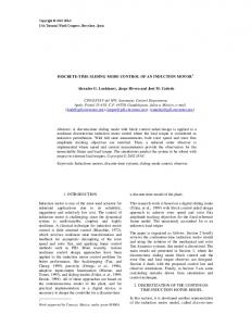
The implementation in real world of that kind of control law requires the use of some hysteretic characteristic. Otherwise, the frequency of commutations goes to infinite. In this case, we used a hysteresis window of width equal to 0.4 in the value of s(i). We simulated the system with PowerDEVS, using parameters R = 10, L = 0.35, A = 12, ω = 25, and c = 380. For the QSS2 method we choose a quantum ∆q = 0.01 which in absense of state events would ensure an absolute error less than 0.01A in the value of i(t). The simulation of the first second was completed after 2509 internal transitions at the integrator, 2508 commutations in the hysteretic comparer and 398 steps at the sinusoidal generator. The total number of steps was then 5415. The results are shown in Figs.3–4. We simulated the system again, but with a final time of 100 seconds in order to measure the execution time. In this case the simulation took 5 seconds (which permits concluding that the execution time of the previous simulation was of the order of 50msec). Then we repeated the experiments using all the variable step methods of Simulink (we discarded fixed step because they would need a very small
We propose the control surface,
15
s = c · (ω − ω0 ) + ω˙
10
(12)
which results in the control law: ua = −K · sign(s)
5
In order to add more realistic features, we considered that the control is implemented on a digital device.
0
−5
−10
−15
(13)
0
0.1
0.2
0.3
0.4
0.5
0.6
0.7
0.8
0.9
1
Fig. 3. Current in the RL circuit
We choose the motor parameters La = 3mHy, Ra = 0.05Ω, km = 6.7851V · s/rad, bm = 0.005N · m · s, and Jm = 15kg · m2 (which correspond to a real machine). The control parameters were c = 20 and k = 480, with a sampling period Ts = 0.0001. We simulated the startup of the motor until the first 5 seconds using the QSS2 method with quanta 0.001 in the speed and 0.1 in the current. The results are shown in Figs.5–6.
12
10
8
60
6
50 4
40 2
30 0
−2
20 0
0.005
0.01
0.015
0.02
0.025
0.03
0.035
0.04
0.045
0.05
Fig. 4. Current in the RL circuit (startup) step size in order to hit the events). We used a relative tolerance of 0.1% so we get a similar accuracy to QSS2 with a quantum of 0.01. In all the cases, the number of steps was about 7430, and the results are very similar to what is shown in Figs.3–4.
10
0
0
0.5
1
1.5
2
2.5
3
3.5
4
3.007
3.008
4.5
5
3.009
3.01
Fig. 5. Speed in the DC motor 59.6965
59.696
Despite the number of steps was not much bigger than in QSS2, the simulation of the first 100 seconds took now 66 seconds on the same computer. Thus, the use of the QSS2 method in PowerDEVS reduced the execution time in more than 13 times compared with Simulink. The reason of this reduction is not only due to the fact that QSS2 performs less steps, but also due to the simplicity of the algorithm, which was conceived to show an asynchronous behavior and it does not need to iterate to hit the events.
4.2 Control of a DC Motor The following SES describes the dynamics of a DC motor with constant field excitation, 1 dia = (ua − ia · Ra − km · ω) dt La dω 1 = (km · ia − bm · ω) dt Jm
59.6955
59.695
59.6945
59.694
59.6935
59.693
59.6925
3
3.001
3.002
3.003
3.004
3.005
3.006
Fig. 6. Speed in the DC motor (detail of the permanent regime) The simulation was completed after 11242 and 19578 internal transitions in the integrators which calculate ω and ia respectively. Considering also the 50000 transitions performed by the controller (i.e. 5/0.0001) the total number of steps was 80280. The execution time was about 0.92sec. The experiment was then improved taking into account that the controller does not change its
output value at every sample. Thus, we modified the DEVS model so that it only produces output events after changes in its output value. Consequently, the number of transitions at the controller was reduced from 50000 to 16529 (which is the real number of commutations in the controller output). That makes a total of 47349 steps, which are executed in about 0.7sec. Variable step algorithms of Simulink need 50000 steps to complete the simulation, but the execution time is now about 56sec. Although the number of steps is similar to QSS2, the complexity of each step is much greater now. Moreover, each discrete time step involves several full function evaluations while each discrete event step involves calculations in a part of the system.
5. CONCLUSIONS We showed that quantization based methods can provide an efficient solution to the problem of simulation of SCMS. Although it was already known that QSS and QSS2 are well suited methods for discontinuous systems, their use in these hybrid control schemes exhibits very significant advantages with respect to discrete time methods. In spite of the performance observed, this work is just a first attempt to apply discrete event methods in the simulation of hybrid control schemes. Taking into account the way in which QSS and QSS2 exploit sparsity and separate the problems, we expect these methods to show even more advantages when dealing with larger and more complex control systems. Thus, the following steps are pointed to continue this analysis over system of increasing complexity. There, it is also interesting to study hybrid control systems other than SMCS. Long term future work should deal with the theoretical properties in order to give some extension of them to be applied to these hybrid cases.
REFERENCES F.E. Cellier. Combined Continuous/Discrete System Simulation by Use of Digital Computers: Techniques and Tools. PhD thesis, Swiss Federal Institute of Technology, 1979. J.M. Esposito, V. Kumar, and G.J.: Pappas. Accurate Event Detection for Simulating Hybrid Systems. In HSCC, volume 2034 of Lecture Notes in Computer Science, pages 204–217. Springer, 2001. Flavia Felicioni and Ernesto Kofman. Simulaci´ on por Eventos Discretos de Sistemas de Electr´ onica de Potencia. In Proceedings of
RPIC’03, volume 1, pages 134–139, San Nicolas, Argentina, 2003. John L. Hung, Weibing Gao, and Hung James C. Variable structure control: A survey. IEEE Transaction on Industrial Electronics., 40(1), february 1993. E. Kofman. A Second Order Approximation for DEVS Simulation of Continuous Systems. Simulation, 78(2):76–89, 2002. E. Kofman and S. Junco. Quantized State Systems. A DEVS Approach for Continuous System Simulation. Transactions of SCS, 18(3): 123–132, 2001. E. Kofman, J.S. Lee, and B. Zeigler. DEVS Representation of Differential Equation Systems. Review of Recent Advances. In Proceedings of ESS’01, pages 591–595, 2001. Ernesto Kofman. Quantization–Based Simulation of Differential Algebraic Equation Systems. Simulation, 79(7):363–376, 2003. Ernesto Kofman. Discrete Event Simulation of Hybrid Systems. SIAM Journal on Scientific Computing, 2004. in press. M. Otter and F.E. Cellier. The Control Handbook, chapter Software for Modeling and Simulating Control Systems, pages 415–428. CRC Press, Boca Raton, FL, 1996. Esteban Pagliero, Marcelo Lapadula, and Ernesto Kofman. PowerDEVS. Una Herramienta Integrada de Simulaci´ on por Eventos Discretos. In Proceedings of RPIC’03, volume 1, pages 316– 321, San Nicolas, Argentina, 2003. T. Park and P.I. Barton. State Event Location in Differential-Algebraic Models. ACM Trans. Mod. Comput. Sim.,, 6(2):137–165, 1996. L. Shampine and M. Reichelt. The MATLAB ODE Suite. SIAM Journal on Scientific Computing, 18(1):1–22, 1997. L. Shampine and S. Thompson. Event Location for Ordinary Differential Equations. Computers and Mathematics with Applications, 39:43–54, 2000. H. Sira-Ramirez. Differential control methods in variable-structure control. International Journal of Control, 48(4), 1988. B. Zeigler, T.G. Kim, and H. Praehofer. Theory of Modeling and Simulation. Second edition. Academic Press, New York, 2000. B. Zeigler and J.S. Lee. Theory of quantized systems: formal basis for DEVS/HLA distributed simulation environment. In SPIE Proceedings, pages 49–58, 1998.