Jun 1, 1993 - backtracks a link previously traversed in the forward direction. It is not obvious how to emulate backtracking in a unidirectional network. One of ...
Distributed algorithms for Unidirectional networks Yehuda Afek�
Eli Gafniy
June 1, 1993 Abstract We address the question of distributively computing over a strongly connected unidirectional data communication network. In unidirectional networks the existence of a communication link from one node to another does not imply the existence of a link in the opposite direction. The strong connectivity means that from every node there is a directed path to any other node. We assume an arbitrary topology network in which the strong connectivity is the only restriction. Four models are considered: Synchronous and asynchronous, and for each we consider node space availability which grows as either O(1) bits or O(log n) bits per incident link, where n is the total number of nodes in the network. First we provide algorithms for two basic problems in distributed computing in data communication networks, traversal, and election. Each of these basic protocols produces two directed spanning trees rooted at a distinguished node in the network, one called in-tree, leading to the root, and the other out-tree, leading from the root. Given these trees we e�ciently transform bidirectional algorithms to run on unidirectional networks, and in particular solve other problems such as the broadcast and echo [Cha79] in a way which is more e�cient (O(n2 ) messages) than direct transformation (that yield O(nm) messages algorithm). The communication cost of our traversal and election algorithms are both O(nm + n2 log n) bits (O(nm) messages and time), where m is the total number of links in the network. The traversal algorithms for unidirectional networks of nite automata, achieve the same cost (O(nm + n2 log n) bits) in the asynchronous case, while in the synchronous case the communication cost of our algorithm is O(mn) bits. Computer Science Department, Tel-Aviv University, Ramat-Aviv 69978 Israel Computer Science Department, University of California, Los Angeles, California 90024, the work of the second author was Supported by NSF Presidential Young Investigator Award under grant DCR84-51396 & matching funds from XEROX Co. under grant W881111. � y
1
1 Introduction Distributed network protocols research has focused most of its e�ort on bidirectional networks. However unidirectional networks appear more often than expected. Unidirectional networks appear as a result of a failure of a link or a subset that disrupts communication in one direction but not in the other. For example the modem circuit at one end could fail to receive (or send) data but is still operating correct in the other direction. Networks with unidirectional links are also found in radio networks with asymmetric transmission matrices due to di�erences in transmission power of the stations, in ber optic, and in VLSI [ELW90]. In this paper we consider both asynchronous and synchronous unidirectional networks. For election, a problem that we solve over this networks, each node needs at least O(log n) bits of memory, where n is the total number of nodes in the network. Our algorithms require as much. However in solving the traversal problem we consider two possibilities of memory space availability. In one case a node has memory that grows logarithmicaly in n. In the other case the memory stays nite. More precisely, in the rst model O(log n + d� ) bits of memory are available for the algorithm in node � , where d� is the degree of node � . In the second model only O(d� ) bits of memory are available at each node. Note that any distributed algorithm for a strongly connected unidirectional network is obviously also an algorithm for a bidirectional network.
1.1 Unidirectional network traversal { background In the traversal problem, one node, called the root, creates a token, which has to visit all the nodes in the network one at a time. When the token arrives at a node the algorithm has to make two decisions. First, whether there are any more unvisited nodes in the network and second, in case there are, to which outgoing neighbor the token should be passed. This is similar to an on-line version of the \Chinese post man" problem: A post person is placed in a new city in which some or all the streets are one-way. The post-person has to traverse all the streets of the city but he has no map or any global information on the topology of the city. The question is to devise a strategy by which he will traverse the minimum number of streets, retracing streets as few times as possible. There are two dual ways in which we can view the token. One view is that of a mail letter. It is going from place to place. The decisions about the route are made by sequence of local post-o�ces, while the letter may carry on it some \control information", e.g. address. This view supports the traversal as handing over a token from node to node. The other is that of the post-man above. It is the actual route- decision maker who pass from node to node, while being allowed to leave \marks" in various nodes. This view supports viewing traversal as a 2
process (single thread of control program) that passes from node to node reading from and writing to the nodes. As it may be convenient we will use these two views interchangeably. Clearly, to be able to traverse a bidirectional network, the network has to be connected. Similarly, to traverse a unidirectional network, the network has to be strongly connected i.e., there should be a directed path from every node to every other node. Message complexity of (m) is obviously a lower bound to any traversal algorithm, where m is the total number of links in the network, since every link in the network has to be traversed. Otherwise, an untraversed subnetwork could reside in the midst of any untraversed link. The problem of distributively traversing a bidirectional network has been thoroughly investigated. One such obvious algorithm is based on Depth First Search (DFS) algorithm [Tar72, HT73]. In the resulting DFS traversal the process makes 2 � m hops, and the number of memory bits it uses at each node is linear in the degree of the node. In solving the unidirectional traversal problem we would like to adapt the bidirectional DFS traversal. Alas, DFS employs backtracking, i.e. a step in which the DFS process backtracks a link previously traversed in the forward direction. It is not obvious how to emulate backtracking in a unidirectional network. One of the contributions of this paper is such a backtracking scheme. It is facilitated by constructing, on the y, a structure called in-directed forest . With the help of the in-directed forest the process identi es a path which brings it from the head of the link which is to be backtracked to its tail. The construction of the in-directed forest is reminiscent of the strongly connected components algorithm of Hopcroft and Tarjan [HT73] (see also [Eve79]). In Section 2, three traversal algorithms are presented. Traversal-1 is simple but ine�cient. In many network instances the process of Traversal-1 makes an exponential number of link traversals before terminating. Traversal-2, which is based on the DFS algorithm, makes at most O(n � m) link traversals on any network (i.e. its time complexity is O(n � m)). Furthermore, we show that (n � m) is a lower bound on the number of link traversals (time complexity), in general. Both in Traversal-1 and Traversal-2 O(log n + d� ) bits of memory are required at each node � and the traversing process carries along O(log n) bits. Both achieve the same complexity for synchronous and asynchronous networks. In some applications, such as VLSI, memory size and message length are restricted and the question then arises, could a unidirectional traversal be implemented using only a constant number of bits in every node and with the traversing process carrying some nite amount of information (i.e., in a unidirectional network of nite automata). Traversal-3 is the variant of traversal-2 for nite automata network. In the asynchronous case it makes at most O(n � m + n � log n) link traversals which is optimal in the worst case (dense networks, in which m = (n log n) ). In the synchronous case it makes at most O(n � m) link traversals. Traversal-3 in the case of a unidirectional ring is an example of a problem whose complexity depends on whether the underlying system is synchronous or 2
3
asynchronous [AFL83]. All the traversal algorithms yield a spanning infrastructure of the network, consisting of two rooted spanning trees one called an out-tree, where paths are directed away from the root, and another called in-tree in which paths are directed to the root.
1.2 Unidirectional network election { background In Section 3 we present a distributed algorithm for election in strongly connected unidirectional networks. The algorithm requires O(log n) bits of memory in each processor and its communication complexity is O(n � m + n log n) bits. To design an election algorithm for strongly connected networks we employ traversal-2. As a rst attempt, consider the following straight forward approach; every initiator starts a traversal. Whenever a lower id traversal learns about the existence of an higher id one, it stops. The worst case communication complexity of this algorithm is O((n � m + n � log n) � n) bits, since O(n) traversals could be initiated such that each spends O(n � m + n � log n) bits. Clearly this approach is ine�cient. As a second attempt, one can improve on it by using the modular technique of Korach Kutten and Moran [KKM85] to economically eliminate traversals. Using their technique the communication complexity is reduced to O((n � m + n � log n) � log n) bits, which is still a logarithmic factor away from our complexity. The election algorithm we design employs traversal-2 as the underlying mechanism, but uses it in a more sophisticated way to achieve a communication complexity of O(nm + n log n) bits and O(nm) time. 2
2
2
2
2
1.3 Related work Although most of the results in this paper were derived in [GA84], before other works explicitly investigate unidirectional networks [ELW90, GK84, Kut88, Kut84] (with the exception of [Kob78]), two bidirectional algorithms, the shortest path algorithm of Gallager [Gal76] and the connectivity checking algorithm of Segall [Seg83] both easily suggest unidirectional election algorithms. In [Seg83], Segall presents a connectivity checking algorithm in which at termination every node knows the ids of all the other nodes in its connected component. The shortest path algorithm in [Gal76] exhibits the same property when it terminates. The communication complexity of the two algorithms is O(n � m � log n) bits, and each node is assumed to have O(n log n) bits of memory. The suggested unidirectional variation of the two algorithms proceeds in two phases: In the rst phase, every node acquires the ids of its incoming neighbors; in the second, it acquires the ids of all the other nodes in the network. 4
More speci cally, let an incoming neighbor of node � be a node at the other end of an incoming link of � , and let in{neighbors of � be the set of all the incoming neighbors of � . Let the record of node � be a two- eld data structure, of which the rst contains the id of � and the second the ids of � 's in-neighbors. In the rst phase, every node transmits it's id on all it's incident outgoing links and receives the ids of it's in-neighbors. In the second phase, every node broadcasts its record, via ooding, to all the other nodes in the network. For this purpose, each node � maintains two sets of ids, the received set and the known set. The received set contains the ids of the nodes whose records were already received by � . The known set contains ids which appeared in a record of at least one node from the received set, i.e., ids of nodes whose existence is known to � . Initially, at the beginning of the second phase, the received set of node � contains the id of � , and the known set contains the ids of � and of � 's in-neighbors. Clearly, when the two sets in a node are identical, they contain the ids of all the nodes in the network (which can easily be proved by induction). The communication complexity of the algorithm thus described is O(m � log n) bits; however, assuming that messages sent over one link are received in the order transmitted, i.e. FIFO links, the communication complexity can be reduced to O(n � m � log n) bits by avoiding repeated transmission of the same id over the same link. Note, that for these algorithms each node is assumed to have O(n � log n) bits of memory. Similar adaptation and analysis applies to [Gal76]. Our election algorithm is thus an improvement on the algorithms of Gallager and Segall both in terms of communication complexity and in terms of the number of memory bits required at each node. Furthermore, our algorithm produces the infrastructure of the intree and out-tree mentioned above, which neither Segall's FIFO link case nor Gallager's algorithms provide. Independently yet following this work Kutten [Kut84] has also developed a traversal algorithm for unidirectional networks. He considered only the logarithmic memory asynchronous model for which he derived an O(nm) messages algorithm [Kut88]. Gafni and Korfhage [GK84] designed an election algorithm for unidirectional Eulerian networks, whose message complexity is O(m � log n). A preliminary version of most of the results reported in this paper appear in [GA84]. More recently Even, Litman, and Winkler [ELW90] have proposed a new approach to the problem of traversing a unidirectional synchronous network of nite automata. Assuming that the degree of each node in the network is constant (implying O(m = n)) they derive a traversal algorithm that runs in O(n ) time. They also study the ring squad problem in the synchronous network of nite automata, which is not addressed in this paper. Interestingly the results in this paper and in [ELW90] suggest that the unidirectional network of nite automata is inherently sequential. In the traversal algorithm of [ELW90] more than one message is sent in the network in a given time however it does not improve the time complexity or the communication complexity of our synchronous traversal algorithm 2
2
5
for a network of nite automata and which sends at most one message in the network at any given time. Furthermore notice that for increased space complexity at each node we were not able to improve the time complexity of the traversal algorithm. However, for the election problem and when the space at the nodes is increased to O(n log n) bits the methods of Gallager and Segall can be used to improve the time complexity of our election algorithm but have worse communication complexity. It is interesting whether there is a spectrum of time-space trade-o� here. Perhaps the rst paper to consider the traversal problem in a unidirectional network of nite-automata is that of Kobayashi [Kob78], where he presents an exponential complexity traversal algorithm that is based on the directed depth- rst-search idea.
Organization of the Paper: The rest of the paper is organized as follows: In the next
section, Section 2, we present 4 building-blocks that are to be employed in the design of traversals 2 and 3 and the election algorithm. In Section 3 we present the traversals algorithm. In Section 4 we present the election algorithm, and we conclude in Section 5 with applications and discussion.
2 Traversal of unidirectional networks 2.1 Traversal-1: a simple traversal algorithm The rst traversal algorithm presented is similar to the centralized algorithm of Fraenkel [Fra70], and is composed of two mechanisms: a termination detection mechanism, and a routing mechanism. The termination detection mechanism enables the traversing process to detect when it has traversed all the links in the network. The routing mechanism is used at each node to select the next link on which to send the process such that in a nite number of link traversals the process will detect termination. The termination detection mechanism is implemented by a counter, called the debtcounter which is carried by the process. The root starts the traversal by initializing the debt counter to zero and sending the process to itself. The counter is incremented by one as soon as the process arrives at a node for the rst time (i.e., when the process is initially received by the root the counter is incremented to one). Then the counter value is tested, if it's value is zero then the process is stopped at this node (see Figure 1). Otherwise, the counter is decremented by one just before leaving a node through its last untraversed outgoing link. After leaving a node at least once through each of its out-going links, the debt counter is never changed again at this node. 6
Lemma 1 The debt-counter is equal to zero when it is tested (in Line 4 in the code of Figure 1) if and only if all links have been traversed.
Proof: ( ) Clearly, for each newly visited node the process increments the counter by one.
Similarly, for each visited node whose outgoing links have been all traversed, the process decrements the counter by one. Hence, when all links are traversed, the counter has been incremented and decremented the same number of times and is therefore back to its initial value. (!) Assume that the counter is zero but not all the links in the network have been traversed. Since the network is strongly connected there is a directed path from a visited node to the tail node of any untraversed link. Let l be the rst untraversed link on one of these paths. Thus, l is untraversed and it's tail node � was visited. Hence, the counter was incremented at least once more (at � ) than it was decremented, which leads to contradiction.
The mechanism implied by Lemma 1 may serve a termination detection mechanism. However, the process needs to employ a routing rule that will lead to termination. We present di�erent routing rules, which lead to di�erent traversal algorithms. This algorithms are presented in this and the next section. The routing rule used by traversal-1 is as follows: Every node orders its outgoing links cyclically, i.e., the rst link in the order follows the last one. Each time that the process arrives at a node it is sent on the next outgoing link according to the cyclic order.
Lemma 2 Using the above routing rule the process eventually traverses all the links. Proof: Assume the contrary. Then, since the network is strongly connected and nite,
there must exist a set S of nodes that have been visited in nitely many times. Thus by the routing rule each of the outgoing links of a node in S has been traversed in nitely many times. Consequently, any node reachable from S has been visited in nitely many times. Since the network is strongly connected S is the whole set of nodes. Since each of the links outgoing from S has been traversed in nitely many times, in particular each of the links has been traversed at least once, contradiction. Lemmas 1 and 2 suggest the traversal algorithm of Figure 1. Initially all nodes and links are assumed to be unmarked. To start the algorithm the root initiates a process with a debt counter set to zero and sends the process to itself (i.e., it places the process in its input queue). Figure 2 is an example of a network on which Traversal-1 requires 2n? link traversals. Let Nl be the number of traversals over link l in some execution of the algorithm. Clearly, 1
7
Response to receiving process(Debt counter) at node � /* Also performed by the initiator with Debt counter = 0 */ 1. If � is unmarked then begin mark � Debt Counter := Debt Counter + 1 ;
2. 3.
end 4. else if Debt Counter = 0 then stop;
5. let l be the next link in the cyclic order of � 's incident links. 6. If l is unmarked 7. 8. 9.
then begin end
mark l If l is the last unmarked link of � then Debt Counter := Debt Counter ? 1 ;
10.Send the process(Debt Counter) over l Figure 1: Traversal-1
N = 2 � N L = 2 � N R and NiL = 2 � N i L = 2 � N i R for i = 1 � � � n ? 1. Since NnL and NnR are both equal to 1 by the end of the traversal, N = 2n? . 0
1
1
( +1)
( +1) 0
1
2.2 Traversal-2: Simulating Directed Depth First Traversal The source of traversal-1's ine�ciency is the routing procedure. A di�erent routing rule is employed in this section to derive a traversal which requires O(n � m) link traversals. We present the algorithm of Traversal-2 in three stages. First, a bidirectional depth rst traversal algorithm is described. Second, a unidirectional implementation of the rst algorithm is presented by assuming that a structure, called spanning in-directed tree, is available. Finally, a mechanism to build the in-directed tree on the y is given, thus providing a unidirectional traversal algorithm.
2.2.1 Bidirectional directed depth rst traversal Throughout the rest of the section we make a distinction between unidirectional and directed networks. A unidirectional network, as de ned before, is a network in which some or all the links are unidirectional links. A directed network is a bidirectional network in 8
1R 1L
0 2R
2L 3R n
3L
4R
nR
nL
Figure 2: An example for the exponential complexity of Traversal-1.
9
which a unique direction is associated with each link. The link directions are given as part of the problem de nition. Here we assume that the directed graph induced by the directions associated with the links is strongly connected. In the bidirectional directed depth rst search algorithm [HT73], the root spawns a process which visits all the nodes in the network. Upon arriving at node � for the rst time, say through link l, the process marks � as active , l as the parent link of � , and iteratively traverses each of � 's incident out-going links. If the process arrives at an already marked node, it backtracks to the node from which it came. After backtracking on all of � 's incident out-going links, the process marks � as fully-backtracked and backtracks from � on the parent incoming link, l. The traversal is completed when the root is marked fully-backtracked. A formal description of the algorithm is given in Figure 3. Note that the process passed between the nodes is merely a token. It does not carry any information except its actual presence. Unlike this traversal, in the next sections we will use the process to carry control information between the nodes. The proof of the algorithm is a simple modi cation to the proof given in [Eve79]. The interested reader is referred to [Afe85] for the detailed proof. Here we only state the lemmas and corollaries.
Lemma 3 The bidirectional directed depth rst process traverses every link in the network at most once in each direction.
Corollary 4 The above traversal algorithm eventually terminates. Lemma 5 The bidirectional depth rst process traverses every link in the network once in each direction. Corollary 6 The number of link traversals made by a traversing process in the bidirectional depth rst search is exactly 2 � m. 2.2.2 Unidirectional depth rst traversal, using a spanning in-directed tree The following two observations are used in this section to implement the bidirectional depth rst traversal on a unidirectional network in which an in-directed spanning tree is de ned. The resulting traversal makes n � m link traversals in the worst case. Let the parent node of every node � , except the root, be the node from which the process arrived at � for the rst time. At any given time, the link through which the traversing process left an active node most recently is called active link. 10
Initially all nodes and links are unmarked. To start, the root s performs: mark s active ; select a link l0, outgoing from s ; mark l0 active ; send the process over l0 ;
Response to receiving the process at node � over incoming link l If � marked then send the process back over l ; else mark � active ; mark l parent ; select a link, l0, outgoing from � ; mark l0 active send the process over l0 ;
end Response to receiving the process at node � over outgoing link l
mark l backtracked ; If there is an unmarked outgoing link l0
then
mark l0 active ; send the process over l0
else end
mark � fully-backtracked ; If there is no parent link then stop ; else send the process over the parent incoming link ;
Figure 3: The bidirectional directed depth rst traversal algorithm
11
LEGEND Fully-backtracked
root
root
Active node Active link Traversed link
intree
intree
FOCAL POINT
Figure 4: The active path
12
FOCAL POINT
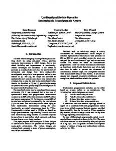
Observation 1: The active nodes together with the active links form a directed path, called the active path. The rst node on the active path is the root and the last link in the path either closes a cycle of active links (see Figure 4), or leads to a node that is either fully-backtracked or newly discovered. The most recently marked node among the active nodes is called the focal point of the traversal (e.g. see Figure 4). Observation 2: All backtracking are over the last link of the active path, i.e., either from an active node, or from a fully-backtracked node to the last active node on the active path.
Observation 1 follows inductively from the fact that every node has at most one active out-going link, and if it has one it must have an active incoming link (the parent link). Observation 2 follows immediately from Observation 1 and the algorithm. An in-directed tree (or, in-tree) is a subnetwork in which every node, except one node, called the root, has exactly one out-going link, the underlying undirected graph is a tree, and all links are directed towards the root. An in-directed spanning tree is an in-tree which spans the network. The di�culty in emulating the directed depth rst traversal on a unidirectional network is that of emulating the backtrack, since links are unidirectional. In [Kob78], Kobayashi devised a solution to this problem with an exponential overhead, i.e., each backtracking incurred an exponential number of messages. To construct a linear overhead per backtracking, we note that whenever the process wants to backtrack over link l, a directed cycle, called the backtracking cycle is de ned by concatenating: l, the unique path in the in-tree from the head node of l to the root, and the active path. Thus, to backtrack over link l (from the head node of l to its tail node) the process goes along the backtracking cycle until it arrives at the tail node of l. To this end, the unique ids of each node are used by the process to identify the tail node of l. Note that shortcuts are possible if the unique path of the in-tree intersects the active path before reaching the root (i.e., whenever the cycle is not simple). In particular, if the head node of l is active the process needs to follow only the active path in order to backtrack to l's tail node. A formal description of the traversal algorithm is given in Figure 5. The lines marked \I" are the code that the initiator has to execute in order to start the traversal. To implement the backtracking mechanism, whenever the traversing process traverses link l from node � to node u it carries the id of � . If u is unmarked (unvisited yet) then node u remembers that � is its parent. If node u is already marked, the process follows the cycle until it arrives back to � . When node u becomes fully-backtracked the traversing process is sent along the backtracking cycle to u's parent.
Lemma 7 The number of link traversals made by a traversing process in the unidirectional depth rst traversal is a most n � m. 13
Proof: In Lemma 2 we saw that every link is backtracked exactly once. The lemma follows
since in each such backtracking the process goes around a cycle of length at most n. In Subsection 2.5 it will be shown that (n � m) is also the lower bound on the number of link traversals.
2.2.3 On the y in-tree construction In this section we do away with the assumption that an in-tree is available by constructing the in-tree on the y, while the process is traversing the network. The essential use of the in-tree in the previous section was to backtrack from a fullybacktracked node. Backtracking from an active node is accomplished simply by following the active path. While a node is active it computes it's unique out-going link in the in-tree, called intree as described below. While an active node may change its choice of the intree link, a fully-backtracked may not. In this section we will maintain the following property throughout the algorithm execution: Property 1: From any fully-backtracked node the unique path de ned by following the intree marked links, leads either to an active node, or if there are no active nodes, to the root.
The basic idea of the intree link selection is based on Property 1, above. We observe that the property is provided by maintaining a simpler property: Property 2: From any fully-backtracked node v the unique path de ned by following the intree marked links leads to a node that was discovered before v (i.e. a node that would have a lower depth rst number if such were assigned).
That is, at the time that v becomes fully-backtracked (i.e. when it's parent is still active) the intree links lead from v to some node u that is still active. The observation is that recursive applications of Property 2 ensure Property 1 (i.e. apply Property 2 to u etc, as is formally stated and proved in Lemma 8). Since the network is strongly connected a path like the one that is required by Property 2, exists. Consider each backtracking cycle. Each such cycle consists of zero or more intree links and zero or more active links. If a backtracking cycle goes over an active link (t ! h), and it is the rst time that a backtracking cycle goes over this active link then, from h's point of view, this cycle contains a path that leads from h to a node that was discovered before h was. Thus, the active links along the cycle, from h to the focal point, should be marked as intree links. Clearly such demarcation would not violate the property for descendants of h on the active path because this new intree path also provides them with property 2. 14
To implement the above idea every node remembers whether or not its parent incoming link has already participated in a backtracking cycle. When the parent incoming link of node � participates in a backtracking cycle for the rst time all the active nodes from � to the end of the active path select their present active link as their intree link. In the rest of this section a parent link which has never participated in a backtracking cycle is called a bridge. Aside form the in-tree construction, the traversal is the same as the depth rst traversal of the previous subsection. It is assumed here that whenever a shortcut in the backtracking cycle is possible it is done, i.e., the backtracking cycle is a simple directed cycle. The mechanism to construct the in-tree can be viewed as an approximation of the mechanism to determine the low-points of vertices in a directed graph, which was introduced by Hopcroft and Tarjan [HT73, Eve79] in their algorithm for strongly connected components. A formal description of the traversal algorithm, with the in-tree construction, is obtained by adding the code in Figure 6 to the code in Figure 5. The codes are combined in the following way: In case the traversal process arrives at an active node in the backtracking mode, then rst the corresponding code in Figure 6 is executed and only then the corresponding code of Figure 5 is executed. The lines that are marked by an "I" are the steps which the root executes in order to start the traversal. In this algorithm node � knows which of its incoming links is the parent link by recording the id of the node on the other side of the parent link, this is the parent node of � . The rst time that a parent incoming link of node � participates in a backtracking cycle is easily detected, as it is exactly the second time that the process arrives at � through this link. To this end, a boolean variable, called BrdgHd (Bridge Head), is used at every node to indicate whether or not its parent incoming link is a bridge (i.e., if it has already participated in a backtracking cycle). Another boolean variable, called XBrdg (crossed bridge), is used on the traversing process to indicate whether or not the current backtracking cycle goes over a bridge. Whenever the process arrives at an active node � , in the backtracking mode, and the XBrdg indicator is on, � selects its active link to be its intree link. Aside from BrdgHd, every node � has the following elds: id which is the id of � , parent which is the id of the parent node of � , activelink which points to the activelink of � , intree which points to the intree outgoing link of � . Aside form XBrdg, the traversing process p, has the following elds: mode which indicates whether the process is now backtracking or not, PreviousNode which is the id of the node that p visited last, FocalPoint which is used in the backtracking mode and is the id of the backtracking destination node. It remains to prove that the intree links selected by any fully-backtracked node span all these nodes and always lead to an active node. Let us de ne an in-directed forest as a collection of disjoint in-trees.
Lemma 8 The intree marked links of the fully-backtracked nodes constitute an in-directed 15
Response to receiving the traversal process, P , at node � : If � is an unvisited node: I I I I
�:parent := P:PreviousNode ; �:activelink := any unused out-going link ; mark � active P .PreviousNode := � .id ; send P over � .activelink ;
fThe "I" mark lines that are executedg fby the root to start the algorithmg
If � is an Active node and P is in the Forward mode: P .mode := backtrack ; P .FocalPoint := P .PreviousNode ; P .PreviousNode := � .id ; send P over � .activelink ;
If � is an Active node and P is in the backtrack mode: if � .id = P .FocalPoint then begin f� is the destination of the backtracking g if there are unused out-going links then begin � .activelink := any unused out-going link ; P .mode := Forward end else begin; fNo more unused out going links : g mark � fully-backtracked ; if � has no parent then STOP; f� is the root g P .FocalPoint := � .parent ; end end P .PreviousNode := � .id ; if � is still marked active then send P over � .activelink ; else send P over � .intree ;
If � is a Fully-Backtracked node:
if P .mode = Forward then begin P .mode := backtrack ; P .FocalPoint := P .PreviousNode ; end ; send P over the intree link ; Figure 5: Traversal-2, The unidirectional depth rst traversal algorithm 16
Response to receiving the traversal process, P , at node � : If � is an unvisited node: �:BrdgHd := true ; fBrdgHd since � 0s parent link have not yet been on a cycle g Continue with the code of Figure 5 for the same case (unvisited � )
If � is an Active node and P is in the backtrack mode: if (� .BrdgHd) and (P .PreviousNode =� .parent) then begin f1-st time that � 's parent link is on a backtracking cycleg P .XBrdg := true ; � .BrdgHd := false ;
end if P .XBrdg then � .intree := � .activelink ; if � .id = P .FocalPoint then P .XBrdg := false ; f� is the destination of the backtracking g Continue with the code of Figure 5 for the same case (Active � and P in the backtrack mode) Figure 6: Traversal-2, The additional code for the in-tree construction. forest.
Before proving the lemma we note the following two implications of its proposition; First, if there are still active nodes, then the roots of in-trees in the forest must be active nodes, which is exactly what we need for the backtracking process. This is because all the fullybacktracked nodes have an intree out-going link which obviously cannot lead to an unvisited node. Second, the proposition implies that when the algorithm terminates the intree links constitute a spanning in-directed tree rooted at the traversal initiator, the root. Proof of Lemma 8: The claim will be proved by induction. Clearly, the lemma holds when the algorithm starts at a time when no node is fully-backtracked (FBT). It is also clear that the lemma holds when the rst node to become FBT, becomes FBT, since one node with one outgoing link are a legal tree. Assume that the claim holds just before node � becomes FBT, and we will prove that it holds after � becomes FBT. If � is the root then the claim certainly holds, since � selects no in-tree link. Henceforth assume � is not the root, and when � becomes FBT there is at least one active node in the network (the root). Assume to the contrary that after � becomes FBT the claim does not hold. Let B be the set of nodes which were already visited before � was visited for the rst time. Let A be the set of nodes that includes � and all the nodes that were visited for the rst time 17
after � was, and before � became FBT. Let L be the set of links which are directed from a node at A to a node at B . Clearly, L 6= ; since the network is strongly connected. By the de nition of A and B there is no traversed link from B to A except the parent link of � , before � becomes FBT. Thus, all the in-trees in B are rooted at active nodes in B and each backtracking cycle, Cl, which is associated with each l 2 L passes from B to A on the parent link of � . Clearly, at least one Cl; l 2 L passed on a bridge (the parent link of � was a bridge when � was visited for the rst time). Let link, l� = (a ! b), be that link in L whose associated backtracking cycle, Cl� , was the last cycle among the backtracking cycles associated with the links in L, to pass over a bridge before � becomes FBT. Cycle Cl� is used as a backtracking cycle for the rst time when l� is traversed for the rst time, which is when a is still active. Since at this time Cl� passes over a bridge, all the links from � to b on Cl� must have been marked as intree links. Since no node in B becomes FBT after � is visited and before � becomes FBT, no intree mark of a node in B is changed at that period. Also, since Cl� is the last backtracking cycle to pass over a bridge before � becomes FBT, all the intree marks along Cl� do not change before � becomes FBT. Hence, the intree link that have been selected by � when � becomes FBT, cannot close a cycle of FBT nodes and intree marked links. Contradiction.
2.2.4 Reducing the communication complexity of Traversal-2 to O(n�m+n log n) bits 2
In this section Traversal-2 is modi ed so in at most 2n ? 2 of its backtracking the process will carry O(log n) bits around the backtracking cycle. In the rest of the backtrackings the process need not carry more than a constant number of bits. Thus reducing the bit complexity from O(n � m � log n) to O(n � m + n � log n). A variation of the traversal presented here is also presented in Section 4 in a much di�erent setting. The modi cation of the algorithm is as follows: 2
1. Every active node uses a boolean variable, called the focal point, to assert whether or not it is the focal point of the traversal. If the focal point variable of node � is false then � is not the focal point of the traversal. When � is visited for the rst time it sets its focal point to true. When � becomes fully-backtracked it sets its focal point to false. 2. Whenever the process arrives in the forward mode at an already marked node (i.e. an active node), � , a two phase backtracking is started. In the rst phase the process is sent around the backtracking cycle and back to � , counting whether there is one or more nodes on the backtracking cycle whose focal point is true. To this end only a constant number of bits has to be carried around by the process. 18
FOCAL POINT
Case 1
Case 2
Figure 7: Backtracking in Traversal-3 3. If only one node on the cycle has its focal point \on" then, this node must be the node preceding � on the cycle (see Figure 7 Case 1), i.e., it is the backtracking destination. In this case, the process is sent around the backtracking cycle again with a constant number of bits, to the unique node which asserts to be the focal point. Hence, a complete backtracking is performed with the process carrying only a constant number of bits. 4. If more than one node on the backtracking cycle has its focal point \on" then a bridge was included in the backtracking cycle (see Figure 7 case 2) and a backtracking identical to the one used in Traversal-2 is initiated by � (with XBrdg set to true). In this phase of the backtracking all the nodes, aside from the last one on the active path, set their focal point to false. A bridge is included since the active link leaving any node whose focal point is true, aside from the last one, must have led to a new node (i.e., it is the parent link of the next node on the active path) and has never been on a backtracking 19
cycle before (otherwise the focal point would not have been true). 5. The backtracking from a fully-backtracked node remains the same as in Traversal-2 except that the focal point of the destination is set to true. The main claim of this subsection is,
Lemma 9 By the above modi cation the process will have to carry O(log n) bits around a backtracking cycle only 2n ? 2 times. Proof: The process has to carry O(log n) bits around the backtracking cycle either when it
backtracks from a fully-backtracked node to its parent, or when the backtracking cycle goes over some bridge for the rst time. Thus we can associate one such backtracking with each node that becomes fully-backtracked, and one with each bridge. Clearly there are n ? 1 nodes which become fully-backtracked (except the root from which the process never backtracks). Similarly, there are n ? 1 bridge links since each such link is the unique incoming parent link of some node (except the root which has no bridge link entering it). In the remaining m ? 2n + 2 backtrackings the process carries only a constant number of bits. Since every backtracking requires at most n link traversals we get:
Corollary 10 The communication complexity of the modi ed Traversal-2 is O(n � m + n � log n) bits. 2
2.3 Traversal-3: an algorithm for a network of nite automata In this section the assumption that every node has O(log n) bits of memory is relaxed. Instead, every node is assumed to be a nite automation, i.e., to have constant size memory regardless of the network size, in which case the nodes do not have unique ids. Since each node has a constant number of memory bits, the traversing process has to be of constant size too. We will show that with a constant size process the traversal requires at most O(n � m + n � log n) link traversals which is also the bit complexity of the algorithm. Note that the only non-constant space used by Traversal-2 is the usage of O(log n) bits to carry the identity of the backtracking destination (this is also the only usage of the unique ids) in each of the backtrackings considered in Lemma 9. Here we show how each of these backtrackings can be implemented by a constant size process which will go around the backtracking cycle O(log n) times. To recognize the preceding node on the backtracking cycle using a constant size process, we use a solution to the following \last in the ring" puzzle: 2
20
In a unidirectional ring of nite automata, design an algorithm by which a designated node, � , will distinguish the node preceding it, u, form all other nodes.
Lemma 11 The bit communication complexity of the \last in the ring" puzzle in an asynchronous ring is �(n � log n). Proof: A solution to the puzzle works in log n phases. Initially, all nodes except � are
candidates for the position. In each phase we eliminate half of the remaining candidates by sending a token around the ring, alternately marking the candidate nodes even and odd. When the token arrives at � , it remembers the parity of the candidate preceding � . In the next phase, the token eliminates all candidates whose parity di�ers from the parity of the desired node. The last phase is detected by the token when it sees that only one node has not been eliminated. Thus, the token carries one more bit to indicate whether there are one or more nodes that has not yet been eliminated on the cycle. Hence, O(n log n) is an upper bound on the bit complexity of the puzzle. To prove that this is also the lower bound we rst claim that the sequence of bits transmitted over each link must be unique. Otherwise, there must be two distinct links, u ! u , and � ! � , such that both have seen the same sequence. Since the network is asynchronous, u , and � , are in the same state and both have generated the same sequences on their out going links, which implies that their down neighbors u and � are also in the same state. Continuing this argument inductively we conclude that the node preceding the designated one has to be at an equal distance from both u and � . This is a contradiction; hence, the sequence of bits transmitted over each link is unique. Since with blog(n)c ? 1 bits at most n=2 unique sequences can be written, over at least n=2 of the links (log n) bits were transmitted. Thus, (n log n) is also the lower bound. Thus, whenever node � becomes fully-backtracked, or a backtracking cycle with more than one focal point is closed at � , � starts the algorithm described in the proof of Lemma 11 to send the process to the node preceding it. The total bit complexity of the traversal does not change with this modi cation; however, the number of link traversals made by the process is linear with the bit complexity of the traversal, i.e., O(n � m + n � log n). 0
0
1
1
1
1
2
0
2
0
2
2.4 Traversal-4: an algorithm for a synchronous network of nite automata Traversal-3 can be run on a synchronous network without any modi cation in which case it will exhibit the same performances. The question arises whether any gains can be achieved in the synchronous model. Answering that question positively we provide an O(n � m) time and bit complexities traversal algorithm for an arbitrary topology unidirectional synchronous network, which matches our general case lower bound. 21
Following the proof of Lemma 9 and in the same spirit as Subsection 2.3 we show here how each backtracking from Lemma 9 can be implemented by a constant size process which goes around the backtracking cycle O(1) times.
Lemma 12 The bit complexity of the \last in the ring" puzzle in a synchronous ring is �(n).
Proof: (n) is clearly a lower bound since a signal has to go around the ring from the
designated node to the node preceding it. An algorithm to match this lower bound uses two tokens that start moving around the ring from the designated node. The synchronous mode of communication is used to move one token at half the speed of the other token. The fast token makes one hop in each round of the computation while the slow token makes one hop every two rounds. Both tokens are moving for 2n ? 1 rounds, after which the node preceding the designated node removes them from the ring. The fast token catches up with the slow token at the node preceding the designated node after going around two times. The node preceding the designated node is the rst node to receive the fast token for the second time while holding the slow token (each node holds the slow token one extra round). To see this let ft and st be the indices of the nodes holding the fast and the slow tokens respectively at round t. Clearly ft = t mod n and st = d t e mod n. The result follows since n ? 1 is the lowest positive value of t at which ft = s t . 2
2.5 Lower Bounds Arriving at the upper bounds of O(n�m+n �log n) bits and O(nm) bits on the communication complexity for traversal, we wonder what is the lower bound. Much research is still needed in establishing tight lower bounds on the unidirectional traversal problem in general. In this section we present one step in this direction. We show that (n � m) is a lower bound on the number of link traversals required by a single token traversal, i.e., when the traversal is restricted to send at most one message at a time. 2
Lemma 13 (n � m) bits is the lower bound to a single token traversal of a unidirectional
graph of arbitrary topology.
Proof: (by example, Figure 8). The result follows since each traversal of a link from A to
B must be followed by a traversal of the path C. Lemma 13 proves that our traversal algorithm is optimal for dense networks (in which m = (n � log n)) and under the restriction that the traversal has at most one outstanding 22
B
A
n/3 nodes
n/3 nodes
C
n/3 nodes
Figure 8: A network for the (n � m) lower bound. message at a time. Furthermore, it suggests that the algorithm is optimal in the general case.
2.6 Producing a spanning out-tree Traversal-2, -3, and -4, which are di�erent implementations of the same algorithm, can be modi ed to produce a useful structure, called infrastructure, on the network. The infrastructure is the combination of an in-directed spanning tree and an out-directed spanning tree. The in-tree construction was detailed in Section 2.2.3. Here we will describe how an out-tree may be produced by Traversal-2. Note that the de ned infrastructure is a strongly connected subnetwork which spans the network and has 2n ? 2 links. The infrastructure proves to have several practical applications, outlined in Section 4.3. An out-directed tree (or, out-tree) is a subnetwork in which every node, except one, called the root, has exactly one in-coming link and the underlying undirected graph is a tree. Since every node in the out-tree has exactly one in-coming link, there is a unique path from the root to every node in the out-tree. An out-directed spanning tree is an out-tree which spans the network. An example of an out-tree is given in Figure 9. 23
Figure 9: An example of an out-tree. We now explain how every node in the network marks some of its out-going links outtree during the traversal algorithm such that, when the algorithm terminates the collection of outtree marked links constitute a spanning out-tree of the network rooted at the traversal initiating node. To construct an out-tree we make the following observation: The collection of parent links constitute an out-tree. To prove it note the following: (1) Every node, except the root, has exactly one parent incoming link, and (2) Going backward on the path de ned by the parent links from any node � we always arrive at the root. Note (2) follows the fact that the incoming parent link of any node � connects � to a node which was explored before � thus, we cannot close a cycle and we must arrive at the root. To detect the parent out-going links of node � we observe the following: The traversing process leaves node � twice or more through link l (in Traversal-2) while � is active if and only if l is a parent link. Thus, every active node counts whether or not each of its outgoing links has been on a backtracking cycle more than once. If a link participated in a backtracking cycle more than once while � is active then it is a parent link and is marked outtree.
3 Election in unidirectional networks In this section we present a recursive distributed algorithm for election in unidirectional strongly connected networks. One version of Traversal-2 (where an intree is assumed to exist in the network, Section 2.2.2) is used as a tool in the construction of the election algorithm, while Traversal 2 and 3 with no a-priori structures are a special case of the election algorithm as shown in the next Section. 24
3.1 De nitions and Outline The election algorithm is based on the following recursive properties of strongly connected directed multigraphs: 1. The set of links, de ned by selecting one outgoing link from every node, contains a nonempty set of disjoint directed cycles. 2. The subgraph, obtained from G by contracting any of the cycles de ned above into one node, results in a strongly connected multigraph. 3. Repeated application of the operation in 1 and 2 contract G into a single node. The distributed algorithm proceeds in conceptual phases, which follow the above contraction process. When a cycle is detected, its nodes are grouped into a cluster. Similar phases are used in [Hum83]. Initially we consider each node to be a single node cluster. The phases of the algorithm are: selection of an outgoing link from each cluster, called a selected link; detection of cycles among clusters; and contraction of cycles of clusters. A cluster is recursively de ned as follows: 1. A single node is a cluster. 2. A set of clusters that are joined in a ring by their selected outgoing links is a cluster. Recursively we assume that every cluster satis es the following 4 properties (see gure 10): 1. A unique node in the cluster is distinguished as the cluster head . 2. All the nodes in the cluster know the id of the cluster head which is also the id of the cluster . 3. Each node in the cluster, except the cluster-head, has one outgoing link marked as intree link. The collection of intree links forms a directed incoming tree, spanning the cluster and rooted at the cluster-head. 4. A strongly connected subnetwork which spans the cluster, called the infrastructure of the cluster, is de ned on the cluster. The cluster head of the unique nal cluster that contains the whole network is the elected leader. Clearly, a single node cluster satis es the inductive assumptions. It is: the clusterhead of itself; a single node in-tree; and a strongly connected subnetwork. To describe the 25
algorithm we will describe the inductive step, i.e., we assume that a set of clusters which satisfy the assumptions already exists and explain how a bigger cluster which satis es the inductive assumptions is composed out of this set. To select a cluster outgoing link, each cluster head initiates a Depth First Traversal (DFT) process (Traversal-2). The traversal process is used to search for a link which is potentially outgoing from the cluster. For the depth rst traversal algorithm we use the traversal algorithm which was developed in Subsection 2.2.2. To detect a cycle, we use a simple algorithm for election on a unidirectional ring. Each cluster forwards the largest id it has seen. When a cluster receives the same id twice it has detected a cycle. The contraction of a cycle is accomplished by rst electing one of the cluster-heads on the cycle to be the cluster-head of the expanded cluster. Then, the newly elected cluster-head synchronizes the cluster by broadcasting the new cluster-id to all the nodes and, constructing all the inductive requirements on the new cluster. The most expensive phase is the DFT in a search for a cluster outgoing link, because in the contraction phase we lose the DFT information accumulated by all the clusters around the cycle except one. When the cluster-head initiates a DFT in the next phase, the search will have to spend much e�ort regaining all the lost DFT information. However, by selecting the cluster-head of the largest cluster on the ring to be the new cluster-head, we minimize the amount of information lost. Thus, we limit the rate of information loss to the rate of cluster growth (i.e., if a large cluster were contracted with a small one, the amount of information lost is proportional to the size of the small one). In fact, we are able to show that the cost of all the DFT's conducted during the algorithm, is within a constant factor of the cost of a single DFT. Since this point is critical in the complexity calculation, but rather minor to the description of the algorithm, we postpone a detailed discussion of it until the complexity section. After a cluster is formed, its nodes are synchronized to search for an untraversed link outgoing from the cluster. To achieve this synchronization, the in-tree rooted at the clusterhead is used. When a cycle of clusters is contracted into a bigger cluster, all their in-trees are merged into one in-tree, spanning the new cluster. The operations of merging in-trees and searching clusters utilize each other alternately. The structures left by the DFT's are used to modify and merge the separate in-trees around the cycle into one in-tree. In turn, the in-tree in a cluster is used for routing purposes, by its DFT process (see Subsection 2.2.2.). In the next three subsections we present the three phases of the algorithm starting with the cluster outgoing link selection (see gure 10). During the algorithm, links are in one of three states: new , elementary or killed . A new outgoing link is one which has not yet been traversed. An elementary link is a link which was a cluster selected outgoing link during one of the previous stages. The set of elementary links within one cluster forms the infrastructure 26
LEGEND Cluster-head
Node Cluster selected outgoing link Link of the intree Link on the active path
Newly elected Cluster-head
Figure 10: Clusters in the Election Algorithm. of the cluster. A killed link is an already traversed link that has never been selected as the outgoing link of a cluster (i.e., an intra cluster link that is not elementary).
3.2 Selection of a Cluster{Outgoing Link Once a cluster is formed, its head node initiates a DFT algorithm to search the cluster's infrastructure for a node with an untraversed outgoing link. The rst such link to be found is selected as the cluster's outgoing link. If it turns out to be an intra cluster link, the DFT continues where it was stopped in the search of another untraversed outgoing link. If no cluster outgoing link is found, the cluster contains all the nodes of the network, and the algorithm terminates. The cluster outgoing link selection phase begins after the synchronization of the cluster has terminated. The head node of the new cluster initiates a DFT token on the cluster's 27
infrastructure. The token carries the id of the cluster which created it and the maximum cluster-id observed so far (maximum-id). The cluster-id is used to distinguish between interand intra-cluster links, and the maximum-id is used to detect a cycle of clusters. The DFT token searches the cluster for a new link, i.e., a link that has never been used by the algorithm. Doing so, the DFT token leaves behind a trail of active links, which leads from the cluster-head to the token location (which is the traversal focal point). Upon nding a new outgoing link, l, the token traverse link l to node � on the other end of l. If � belongs to the same cluster, the token returns to l's tail via the in-tree and the active path. Link l is then marked killed, and it will never again be traversed. If, on the other hand, the token arrives at a di�erent cluster, the information it carries and the newly selected link it has established enable the cycle detection to continue as describes below.
3.3 Cycle Detection For the sake of simplicity, we have selected an ine�cient algorithm for cycle detection. Since its complexity is, in general, not the bottleneck, we have avoided discussing an improved mechanism for cycle detection (The improvements are a generalization of [Pet82, DKR82], with which our algorithm will perform optimally on rings). After each cluster selects an outgoing link, the network contains at least one cycle which consists of two or more clusters (see gure 10). Let each cluster send its id on the cluster outgoing link. A cluster forwards another cluster-id only if it is larger than all the cluster-ids it has received in the past. Eventually, one and only one cluster in each cycle will receive the same cluster-id twice, thus detecting a cycle. The cluster-head that detected the cycle synchronizes the new cluster. The operation of cycle detection is carried out by the cluster-heads. To implement it, each node receiving a message from a di�erent cluster forwards it to its cluster-head through the cluster's in-tree. To forward a maximum-id from a cluster-head to the next cluster, the cluster-head broadcasts the maximum-id over the infrastructure of its cluster. All nodes (including the cluster-head) retain a maximum-id variable, which is updated by the maximum-id of the broadcast message. The DFT token updates its maximum-id to the largest it encounters along its way. If a cluster outgoing link has been selected, the broadcast message is simply forwarded over the outgoing link to the next cluster. When a cluster-head receives a maximum-id which is equal to its own, it has detected a cycle and it is elected to start the synchronization phase.
28
3.4 Cycle Contraction and Cluster Synchronization In the cycle detection phase a new cluster with an elected cluster-head was found. In this phase the elected cluster-head establishes the remaining three inductive assumptions on the new cluster. The elected cluster-head thus; (1) noti es all the nodes in the clusters around the cycle of their new cluster-id, (2) It combines the in-trees of all the clusters into one in-tree which spans the new cluster and is rooted at the elected cluster-head, and (3) It combines the infrastructures into one infrastructure spanning the new cluster. After receiving a positive acknowledgment that all the nodes have completed these constructions, the elected clusterhead starts the next phase of cluster outgoing link selection. The synchronization phase is carried out by a broadcast with echo mechanism on the cluster new infrastructure. Upon receiving the rst copy of the broadcast message, every node performs the following ve operations in the following order: (1) updates its own cluster-id; (2) If one of its links is a selected cluster-outgoing link then it marks that link as elementary and sends a message to this e�ect over that link. Every node maintains a list of it's incoming elementary links, which it updates on the reception of such messages (this list is necessary for the echo phase of the broadcast and echo described below). (3) It updates (if necessary) its intree mark; (4) It forwards copies of the broadcast message over its elementary outgoing links; and (5) It acknowledges the reception of the message through the in-tree. Any duplicate copies of the message are discarded. The second operation above, has combined the infrastructures into one infrastructure which spans the new cluster.
Merging the in-trees: To merge all the in-trees around the cycle, we use the active paths in each cluster which lead from the cluster-heads to the head nodes of the selected outgoing links. The active paths are constructed during the DFT in the clusters outgoing link selection phase (see 2.2.2). We notice that, if each node of a cluster that has an active outgoing link puts its intree mark on the active link, then the incoming spanning tree is rerooted to the head node of the cluster outgoing link (see gure 11). (Note that the head node of the cluster outgoing link belongs to the next cluster on the cycle of clusters.) To obtain a directed in-tree which spans all the clusters around the cycle, we perform this operation in all the clusters around the cycle except for the elected cluster. Thus, the in-tree formed is rooted at the elected clusterhead. This in-tree is used by the nodes to notify their new cluster-head of the contraction termination. Acknowledging the broadcast: To notify the cluster-head that all the nodes in the new
cluster are aware of their new cluster-id, every node sends an acknowledgment as follows: 29
After
Before
Figure 11: Rerooting an in-tree. After receiving the rst copy and making all the necessary updates, every node sends an acknowledgment over all the elementary outgoing links aside from the intree marked link. An acknowledgment is sent over the intree marked outgoing link only after an acknowledgment has been received on all the elementary incoming links. When the elected cluster-head has received the acknowledgment message over all of its elementary incoming links, the contraction has terminated, and a new phase of cluster outgoing link selection is started. To prevent messages with new and larger maximum-id's from being lost during the contraction phase we speci cally forward them as follows. First, every node that receives a new and larger id forwards it to it's cluster-head in a special message. Second, when a cluster-head broadcast a new and larger maximum-id it also does it in a speci cally marked message. These messages are not destroyed by the contraction operations, unless they encounter a node with a larger maximum-id. Moreover, any new and larger maximum-id which arrives at the cluster-head that have detected the cycle (in such a special message), during the synchronization phase, is held back by this cluster-head. It is re-delivered to the cluster-head upon the termination of the synchronization broadcast and echo.
Termination: The algorithm terminates when a cluster fails to select a cluster-outgoing link. This cluster spans the whole network, its cluster-head is the elected node and its maximum-id is the largest id. 30
3.5 Complexity of the Election Algorithm Communication complexity analysis involves counting the total number of bits transmitted over all the network links. The communication cost of the algorithm has three components: the cost of cluster synchronization, the cost of cycle detections and the cost of clusteroutgoing link selection. We observe the following two facts: Fact 1: The number of cycle detections is, at most, n ? 1.
Fact 2: In a cluster of size k, there are, at most, 2k ? 1 elementary links.
Fact 1 holds because the contraction of a cycle strictly reduces the network size. Fact 2 follows from fact 1 and the observation that there exists a one-to-one correspondence between clusters and elementary links.
Lemma 14 The total cost of synchronizing the clusters is at most O(n log n) bits. 2
Proof: According to fact 1 there are, at most, n ? 1 cluster synchronizations. The synchronization messages propagate on the infrastructure of a cluster which contains, at most, 2n ? 1
links. In each synchronization one broadcast message and one echo message are transmitted on each elementary link. Since each message is of size O(log n) bits the result follows.
Lemma 15 The total cost of all cycle detections is at most O(n log n) bits. 2
Proof: Each time a new cluster head is elected a new maximum-id is sent around a cycle of clusters. Thus, by fact 2, there are at most 2n ? 2 maximum-id initiations. Each such initiation is sent over the infrastructure of some cluster. The same maximum-id is forwarded at most three times on the same link in a particular cluster; once when it enters the cluster and the link is an in-tree link on which it was forwarded to the cluster-head; once when the cluster-head broadcasts the maximum-id; and once on its return to that cluster-head (which then detects a cycle). Since, a link forwards the same maximum-id at most three times for each cluster it belongs to, the result follows. The cost involved in selecting outgoing links consists of the cost of killing intercluster links and the cost of the DFT's. To kill link l, the algorithm transmits one message of O(log n) bits over l and a kill message of size O(1) bits over a path from the head of l to its tail. The kill message goes 31
down the in-tree to the cluster-head and then along the active path to the tail of l. This node is distinguished from other nodes on the active path since it is the focal point of the DFT. Thus, the killing of one link costs O(n) bits. Since the algorithm kills, at most, m links, the killing of intercluster links adds up to, at most, O(n � m) bits. As mentioned, the cost of one DFT on a network with n nodes and m links is O(n � m � log n) since there is one backtracking for each link of the network, and each backtracking costs O(n log n). The DFT operation is employed in the election algorithm to search the infrastructures of di�erent clusters. Since there are, at most, twice as many links as nodes in an infrastructure, the cost incurred by each DFT of a cluster with k nodes is O(k log n). As the DFT could be used n ? 1 times by the algorithm, the total cost of all DFT's might be O(n log n). To reduce the total cost of all DFT's from O(n log n) bits, a special cluster head election phase is added after the cycle detection and before the synchronization phases. In this phase the cluster head which is elected in the cycle detection phase synchronizes the election of the cluster-head of the largest size cluster around the cycle. The new cluster-head then proceeds with the cluster synchronization phase as described before. After synchronizing the cluster, the cluster-head resumes its DFT process from the previous stage, i.e., from the head node of its former cluster outgoing link, thus avoiding re-searching nodes that were already searched. The head node of its former cluster outgoing link is now the last node on the active path. 2
3
3
Cluster-Head Election To elect a cluster-head of a largest size cluster (ties are resolved
by cluster-ids), the cluster-head detecting the cycle sends an elect-message around the alternating sequence of active paths and in-trees which form a directed cycle (see gure 10). On its way, the elect-message nds out which cluster has the largest number of nodes and what the total number of nodes in all the clusters around the cycle is. This information is updated on the elect-message by the cluster-heads along the directed cycle. Once the elect message returns to the originating cluster-head, the control of cluster synchronization is passed to the newly elected cluster-head. Any new and larger maximum-id which arrives at the cluster-head detecting the cycle during the election and the synchronization phase is held back by this node. It is delivered to the new cluster-head upon the reception of the synchronization broadcast. After being elected, the new cluster-head resumes its DFT of the previous cluster outgoing link selection phase. Doing so it uses the active path and the node marks which its DFT had left. The algorithm thus can be viewed as a process in which all the cluster-heads are candidates for leadership. When clusters owned by di�erent candidates form a cycle, the candidate which owns the largest size cluster eliminates all the other candidates. In doing so the candidate merely has enlarged its cluster to include the clusters of the candidates it has eliminated. The DFT structures it had in its original cluster are now extended to search the enlarged cluster. Henceforth, we refer to the clusters which did not change their cluster-id 32
as one cluster which has consumed other clusters during the algorithm. The above scheme is similar in principle to the capturing rule of [Gal77] and of algorithm A in [AG91]. There we enabled the largest candidate, in terms of captured nodes, to kill and take nodes from a smaller candidate. To see that the above scheme does not add more than a constant factor to the complexity of a single DFT, we will use a lemma which was introduced in a similar context by Gallager [Gal77]:
Lemma 16 For any given k, the number of clusters that own n=k nodes or more is, at most, k.
Proof: Let C and C be any two clusters which had size n=k at some point of time. We 1
2
shall show that each of C and C must have had n=k nodes disjointly. If they have never consumed each other, we are done, since the clusters were certainly disjoint. If, w.l.o.g., C has consumed C , then C must have already had n=k nodes at the time of eliminating C . 1
2
1
2
1
2
Corollary 17 The largest cluster to be consumed by another cluster owns at most n=2 nodes,
the next largest at most n=3, etc.
Thus, we arrive at the following:
Lemma 18 The total cost of the DFT's is O(n log n). 2
Proof: The cost of traversing a cluster of size k is at most k log n bits. Hence, the total b nc b nc n n cost is bounded by P ( ni ) messages. But, P ( ni ) � P 2i � ( n ) = P ( n ) � 2n . i i i i Hence, the bit complexity of the depth rst traversals is O(n � log n) bits. 2
2
=1
2
=1
log
=0
2i
2
2
log
=0
2
2i
2
Adding the bit costs of all three components, we arrive at a total communication complexity of O(n log n + n � m) bits for the whole algorithm. By the arguments presented in Subsection 2.5 we conjecture that this is also the lower bound on the communication complexity of the election problem on arbitrary topology strongly connected unidirectional networks. 2
4 The Traversal Algorithm as a Special Case of the Election Algorithm In this section we show how Traversal-2 and -3 can be derived as a special case of the election algorithm. Imagine the behavior of the election algorithm when it is started by a single node. 33
In this case, the initiator initiates a process which visits all the nodes in the network and terminates. In the rst subsection we show that the process can be modi ed to behave exactly as the process in Traversal-2. In Subsection 4.2 we show how Traversal-3 can be derived from the election algorithm. The process of deriving the traversal algorithms from the election algorithm provides a constructive proof of lemma 8.
4.1 Deriving Traversal-2 from the election algorithm Assuming that only one node initiates the election algorithm, we make the following observations: Observation 1: at any given time, at most one cluster is searched, i.e., no messages are exchanged in any of the other clusters. Observation 2: all the clusters and their selected outgoing links form a simple directed path in which each cluster is a node and each link is a selected outgoing link. This path, called the clusters active path , occasionally closes on itself (see gure 12). When the path closes either a cycle of clusters is formed, or the last link on the path is an intra cluster link (in the last cluster on the path, see gure 12, cases 2 and 1, respectively). Observation 2: consider the cluster's active path when it does not close on itself. Then, the nodes at which the cluster's active path enters clusters are the rst nodes to be explored in each cluster. Therefore, if these nodes were selected as the cluster-heads of their clusters, the active paths of all the clusters would form a single contiguous path at all times.
We now modify the election algorithm according to the above observations, namely, in each cluster the rst node to be explored is elected as the cluster-head. Cycle detection (case 2 in gure 12) occurs when the token leaves one cluster C (by traversing its selected outgoing link for the rst time) and arrives at another, previously explored, cluster C . Recalling the third observation, the cluster-head of C is the \oldest" node on the newly formed cycle of clusters. This cluster-head (h) synchronizes the cycle of clusters and, is elected to be the cluster-head of the new cluster. Also, (from the third observation) the active paths around the cycle form a single contiguous path. If the synchronization phase is modi ed to leave all the active paths intact, the distinct DFT's may be considered as one DFT. Thus, the newly elected cluster-head h resumes a DFT which already has an active path going through all the clusters around the cycle. As a result, no node in the network is searched more than once during the whole algorithm. The cluster-head resumes the DFT at the node in which the cycle was detected (the LOOP node in gure 12, case 2). 1
2
2
34
The above variation of the election algorithm can be viewed as a traversal process. One node spawns the process which terminates at the initiator after visiting all the nodes in the network, one at a time. This traversal process can be further modi ed to work on a unidirectional network of nite automata, as we show in the next section.
4.2 Deriving Traversal-3 from the election algorithm Two operations in the preceding traversal algorithm require O(log n) bits memory in each node. The rst is distinguishing an intra cluster from an intercluster link. The second (which occurs during the DFT of the infrastructure) is backtracking from the last node on the active path. In the rst operation, the O(log n) bits are used to distinguish between the case that a newly traversed link, l, is an intra cluster link and the case that l closed a cycle of clusters. This operation was accomplished in the preceding algorithm by comparing the id carried by the token with the cluster-id of the head node of l. To perform the operation without ids, we note that, in both cases, l closed a directed cycle of nodes and links (composed of an active path followed by a path in an in-tree, see gure 12). In the rst case, exactly one cluster-head resides on the cycle while, in the second case, at least two cluster-heads reside on the cycle (see gure 12). We now explain how the token decides whether there is more than one cluster-head on the cycle. The last node on the active path in each cluster is marked focal point (it is the focal point of that cluster's DFT, see subsection 2.2.2). The head node of a newly traversed link l is marked LOOP if it is an already explored node. Upon arriving at a LOOP node, the token is sent around the cycle to nd out whether there is more than one cluster-head on it. Since there is exactly one LOOP node on such a cycle, the walk around it utilizes a nite number of bits on the token. The token then walks around to the focal point, kills l and resumes the DFT. If, on the other hand, more than one cluster-head was found, a cycle of clusters was identi ed. The token then makes another trip around the cycle in order to synchronize its clusters. On the second round, the token rst erases all the focal point marks. Second, it erases all the cluster-head marks, aside from the rst. Third, the token modi es the in-trees of all clusters, aside from the rst one, to be rerooted at the LOOP node (in the same way as was done in the election algorithm). Notice that the active path of the rst cluster lies between the rst and the second cluster-head. Arriving at the LOOP node for the second time, the synchronization phase terminates. The LOOP mark is removed, the focal point mark is put on, and the DFT is resumed. The backtracking in the DFT is performed without using node ids by using the same solution that was suggested in Subsection 2.3. The communication cost of the cycle detection and synchronization phases does not 35
LEGEND Node initiator Cluster-head Focal point LOOP node Cluster outgoing link intree link Active link
Case 1
Case 2
Figure 12: Clusters in the Traversal Algorithm. 36
change in the modi ed algorithm. The cost of the cluster outgoing link selection phases is O(n log n) bits since the DFT searching for outgoing links requires one backtracking for each link of the infrastructure. Thus, the communication complexity of the traversal algorithm is the same as that of the election algorithm. 2
4.3 Applications 4.3.1 Applications of the traversal algorithm In this section we show how the traversal algorithms and their resulting infrastructure can be used to solve other problems. In particular we apply the traversal algorithm to perform broadcasting, route messages, and to systematically emulate any bidirectional algorithm on a unidirectional network. Each of the applications can be solved by a traversal; however, after executing the traversal, the application problems may be solved more e�ciently by using the infrastructure produced by the traversal.
4.3.2 Broadcast with Echo In the broadcast with echo problem one node, the root, has a piece of information which it sends to all the nodes in the network, and the root gets a positive acknowledgment that all the nodes have received the information. A straightforward solution to the problem will use a traversing process to carry the information on it. The message complexity of this solution is the message complexity of the traversal algorithm, O(n � m). After one traversal, the next broadcast with echo can be more e�ciently performed by traversing only the infrastructure links. Since the infrastructure de nes a strongly connected network any node (not only the root) may start a traversal for this purpose. The complexity of this traversal is O(n ) since the number of links in the infrastructure is at most 2n ? 2. After one traversal was performed, a further improvement can be achieved as follows: Every node which wants to start a broadcast with echo rst sends the information of the broadcast to the root node along the out-tree marked links, and then the root node starts a broadcast with echo as described below. After receiving the echo, the root node will broadcast an echo on the out-tree links. The infrastructure can be used for an e�cient broadcast with echo from the root as follows: The root sends the broadcast message on all its out-going links in the infrastructure. Upon receiving the broadcast message for the rst time, every other node sends the message to all its out-going neighbors in the infrastructure. Any other copy of the broadcast message 2
37
is discarded. This implements the broadcast part of the algorithm. To notify the root that all the nodes in the network have received the broadcast message, every node � sends an echo as follows: After sending the copy of the broadcast message, � sends an echo over all of its infrastructure outgoing links except the link marked intree. Node � sends an echo over the intree marked outgoing link only after an echo has been received on all of its infrastructure incoming links. When the root has received the echo over all of its infrastructure incoming links, the noti cation has been completed, and a message to this e�ect is sent on the outtree marked links. The average message complexity of the resulting broadcast with echo algorithm is 6n (averaging out the rst broadcast, which is a regular traversal). Sending the broadcast message from the initiating node to the root of the infrastructure costs at most n?1 messages. The broadcast message is then transmitted once over each infrastructure link which adds at most 2n ? 2 messages to the complexity. The echo message is also sent once over each infrastructure link, hence another 2n ? 2 messages. Then, to pass the echo to the initiating node, another n ? 1 messages are transmitted on the outtree marked links.
4.3.3 Messages sending The in- and out-trees which result from the traversal algorithm enable us to e�ciently send a message from every node to every other node. To pass a message from node � to node u, node � sends the message along the intree marked links to the root which then broadcast the message on the out-tree. Thus, at most 2n ? 2 messages are sent in the routing mechanism, in order to send a message from any node to any other node.
4.3.4 Transforming bi-directional distributed algorithms to unidirectional networks The above routing mechanism can be used as a means to emulate any bidirectional distributed algorithm on a strongly connected unidirectional network. Whenever a node has to send a message on an incoming link, it will use the above message passing mechanism. Thus, if a problem has a bit complexity O(P (n)) on a bidirectional network, then its complexity on the unidirectional network is upper bounded by O(n � P (n) + n � log n + n � m) (the last two terms entail the construction of the infrastructure). In case that the bidirectional algorithm is for a network of nite automata, i.e., if nodes are anonymous then we can send a message backward from node v to its incoming neighbor u by adapting the solution to the \last in the ring" puzzle. However the adaptation costs O(m) messages (bits) in the synchronous network and O(m + n log n) messages in the asynchronous network for each message sent backward. The solution is adapted by performing the algorithm on the cycle de ned by the unique path from v to the root in the in-tree con2
38
catenated with the unique path from the root to u and with the u ! v link. The messages of the protocols in the proofs of Lemmas 11 and 12 are marked di�erently when they go from v to the root and when they travel from the root down to v via the out-tree. Messages going from v to the root behave exactly the same as in the original solutions. Each node participates in the algorithm for a message it receives in the \down" mode over its parent link in the out-tree, and sends the message it would have sent as a response on a ring on all its outgoing links. Any message received by a node other than v, not on the parent out-tree, is ignored, and v responses only to messages it receives from u. This guarantees that messages cycle only on the desired cycle. On all other potential cycles, starting at v the messages are eliminated when they reach a leaf of the out-tree.
5 Concluding Remarks An interesting observation is that the amount of communication in the unidirectional election algorithm, O(n � m + n log n) bits, is n times the number of messages in the optimal bidirectional algorithm. We would obtain the same cost if we were to simulate the bidirectional algorithm, [GHS83] with each acknowledgment charged as n bits, on a unidirectional network. Together with lemma 13, this leads to the conjecture that our election algorithm is as e�cient as possible in terms of communication cost. 2
Acknowledgments We would like to thank Shimon Even and Peter Winkler for encouraging us to rewrite the results reported here. We would also like to thank an anonymous referee for many helpful corrections.
References [Afe85]
Y. Afek. Distributed Algorithms for Election and Traversal in Unidirectional and Complete Networks. PhD thesis, University of California, Los Angeles, October 1985. [AFL83] E. Arjomandi, M. J. Fischer, and N. A. Lynch. E�ciency of synchronous versus asynchronous distributed systems. JACM, 30(3):449{456, July 1983. [AG91] Y. Afek and E. Gafni. Time and message bounds for election in synchronous and asynchronous complete networks. Siam J. on Computing, 20(2):376{394, April 1991. Also in PODC 85. [Cha79] E. J. Chang. Decentralized Algorithms in Distributed Systems. PhD thesis, University of Toronto, October 1979. 39
[DKR82] D. Dolev, M. Klawe, and M. Rodeh. An O(nlogn) unidirectional algorithm for extrema nding in a circle. Journal of Algorithm, 3:245{260, 1982. [ELW90] S. Even, A. Litman, and P. Winkler. Computing with snakes in directed networks of automata. In Proc. of the 31st IEEE Annual Symp. on Foundation of Computer Science, pages 740{745, October 1990. [Eve79] S. Even. Graph Algorithms. Computer Science Press, 1979. [Fra70] A. S. Fraenkel. Economic traversal of labyrinths. Math. Mag., 43:125{130, 1970. [GA84] E. Gafni and Y. Afek. Election and traversal in unidirectional networks. In Proc. of the 3rd Annual ACM Symp. on Principles of Distributed Computing, August 1984. [Gal76] R. G. Gallager. A shortest path routing algorithm with automatic resynch. Unpublished note, March 1976. [Gal77] R. G. Gallager. Finding a leader in a network with �(e) + �(n log n) messages. Unpublished Note, 1977. [GHS83] R. G. Gallager, P. A. Humblet, and P. M. Spira. A distributed algorithm for minimum weight spanning trees. ACM Trans. Program. Lang. Syst., 5:66{77, January 1983. [GK84] E. Gafni and W. Korfhage. Distributed election in unidirectional eulerian networks. In Proc. Twenty-Second Annual Allerton Conference on Communication, Control, and Computing, October 1984. [HT73] J. Hopcroft and R. Tarjan. Algorithm 447: E�cient algorithms for graph manipulation. Comm. ACM, 16:372{378, 1973. [Hum83] P. A. Humblet. A distributed algorithm for minimum weight directed spanning trees. IEEE Trans. Comm., COM-31(6):756{762, June 1983. [KKM85] E. Korach, S. Kutten, and S. Moran. A modular technique for the design of e�cient distributed leader nding algorithms. In Proc. of the ACM Symp. on Principles of Distributed Computing, August 1985. [Kob78] K. Kobayashi. The ring squad synchronization problem for a class of polyautomata networks. Journal of Computer and System Science, 17:300{318, 1978. [Kut84] S. Kutten. personal communication. 1984. [Kut88] S. Kutten. Stepwise construction of an e�cient distributed traversing algorithm for general strongly connected directed networks. In J. Raviv, editor, Proceedings of the Ninth International Conference on Computer Communication, pages 446{ 452, October 1988. 40
[Pet82] [Seg83] [Tar72]
G. L. Peterson. An �(n log n) unidirectional algorithm for the circular extrema problem. ACM Trans. Program. Lang. Syst., 4(4):758{762, October 1982. A. Segall. Distributed network protocols. IEEE Trans. on Information Theory, IT-29(1):23{35, January 1983. R. Tarjan. Depth- rst search and linear graph algorithms. SIAM J. Comput., 1:146{160, 1972.
41