... of a distributed architecture. and IBM T.J. Watson Research Center, Yorktown Heights, NY ...... In Proc. GLOBCOM 89, Dallas Texas, 1989. Tur86] J. Turner.
Distributed control for High Speed Networks Israel Cidon�
Department of Electrical Engineering Technion, Haifa 32000, Israel
Mark Kaplan
IBM T.J. Watson Research Center Yorktown Heights, NY 10598
Inder Gopal
IBM T.J. Watson Research Center Yorktown Heights, NY 10598
Shay Kutten
IBM T.J. Watson Research Center Yorktown Heights, NY 10598
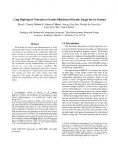
Abstract In this paper we describe a control architectures for a high speed packet switched network. The architecture was designed and implemented as part of the PARIS (subsequently plaNET) networking project at IBM. This high bandwidth network for integrated communication (data, voice, video) is currently operational as a laboratory prototype. It will also be deployed within the AURORA Testbed that is part of the NSF/DARPA Gigabit Networking program. The high bandwidth dictates the need for specialized hardware to support faster packet handling for both point to point and multicast connections. A faster and more e�cient network control is also required in order to support the increased number of connection and their changing requirements with time. The new network control architecture presented in this paper exploits specialized hardware, thereby enabling tasks to be performed faster and with less computation overhead. In particular, since control information can be distributed quickly using hardware packet handling mechanisms, decisions can be made based upon more complete and accurate information. In some respects, this has the e�ect of having the bene ts of centralized control (e.g. easier bandwidth resource allocation to connections), while retaining the fault-tolerance and scalability of a distributed architecture.
�
and IBM T.J. Watson Research Center, Yorktown Heights, NY
1 Introduction Packet switching networks have changed considerably in recent years. One factor has been the dramatic increase in the capacity of the communication links. The advent of ber optic media has pushed the transmission speed of communication links to more than a Gigabit/sec, representing an increase of several orders of magnitude over typical links in most packet switching networks ([KMS87]) that are still in use today. Increases in link speeds have not been matched by proportionate increases in the processing speeds of communication nodes. This implies that switching of information cannot be performed using traditional software store-and-forward functions. Another factor is the changed nature of tra�c carried by these networks. As opposed to pure data networks, or pure voice networks, it is now accepted that packet switching networks (or variants of packet switching networks like ATM ([Bou92])) will form the basis for multimedia high speed networks that will carry voice, data and video through a common set of nodes and links. Real time tra�c (e.g. voice, video) requires that the route selection function be capable of guaranteeing for a long period the availability of adequate network resources along the chosen path for a particular tra�c stream. These streams typically require that a minimal amount of bandwidth be available to them as long as the stream is active. On the other hand, non-real-time services (such as traditional data services) are much less predictable and must be supported on a demand basis. Such non-real-time services can be slowed down or be postponed for a later time when the network is heavily loaded but require quick and prompt setup if resources are available. The increased number and the heterogeneous characteristics of users (or calls) makes traditional network control schemes functionally inadequate and ine�cient. Both above factors have a signi cant impact on the design of the protocols and control procedures for the network. The disparity between communication and processing speeds suggests that processing may become the main bottleneck in future networks. A common partial solution to this problem is to introduce high speed switching hardware which o�-loads the routine packet handling and routing functions from the processing elements ([CGK88]). This issue has been heavily investigated in the literature and several high-speed hardware switches have been described [Tur86]. A second issue, the need for an additional performance and functionally in the network control layer, is much less explored. In this paper we explore this second issue, speci cally focusing on the lessons that we have learned during the design and implementation of the PARIS network ([CG88]). We believe that most of our conclusions are general and can be applied to any high speed packet 1
network. The early stage of PARIS was described in [CG88]. A subsequent paper [CGG+ 92] describes a successor to PARIS called plaNET. (For clarity, we shall only refer to PARIS though plaNET is largely similar as far as distributed control is concerned.) Both works also include some initial ideas regarding distributed control. In the current paper we describe for the rst time the distributed control functions, and the way they t into the complete network. We elaborate on the way in which network control performance can be gained by exploiting specialized hardware features. In particular we introduce new multicast features implemented in hardware, and exploit them in performing fast and computation e�cient information distribution for di�erent network control tasks. We also describe some new algorithmic ideas that save computation overheads associated with previous network control solutions. Our performance measures are stated in terms of worst case time and processing costs associated with the distributed procedures used for network control. Let us now describe the problems solved by the distributed control architecture presented in this paper. The control procedures of the PARIS network facilitate virtual circuit routing. Thus, we have the notion of a "connection" or "call" being established between a source and a destination. For each call, all the tra�c of that call (in one direction) traverses the same path through the network. The control process is as follows. Requests for "calls" arrive at nodes asynchronously. Each call has associated with it some parameters such as average packet rate, burstiness, tolerance for packet loss, etc. Calls are either denied access to the network ("blocked") or accepted into the network. If accepted, a call is provided with a route that has adequate capacity to handle the request. The mechanisms used by each node to perform these functions (accept/deny calls, provide a route and guarantee/reserve bandwidth) are referred to as the control procedures of the network. In a similar way, existing calls might request for additional network resources along the established call path (or release some of the resources not used any more). Traditional data networks typically employ distributed control but do not guarantee availability of bandwidth to calls. They are usually too slow to be extended to perform fast setup and takedown of calls or bandwidth reservations. Their distribution of routing information is usually computational ine�cient because of an extensive use of a software based hop-by-hop information ood mechanisms. Control procedures in common carrier networks (circuit switched networks) deal with capacity allocation but are typically more centralized, rely on the availability of signi cant computing power and support rigid types of reservations which do not change in time. A key contribution of PARIS is showing that by employing hardware speed-ups and new algorithmic techniques in the control ow it 2
is possible to provide performance guarantees, and considerable speed-up of the reservation operation while preserving the fault tolerance and growth capabilities of a distributed control architecture. In particular, we develop a new topology and utilization information update algorithm which employs a hardware based broadcast over a tree replacing the traditional hop-by-hop software ooding employed in previous architectures such as ARPANET ([MRR80]) and APPN [BGJ+85]. The advantages of the new approach are much faster distribution of the topology/utilization information and a major reduction in the processing involved. We develop fault-recovery and load balancing mechanisms to insure its operation under topological changes and rapid changes of network load. In addition, we develop a new call setup/takedown procedure which employs another hardware multicast mechanism and accelerates the bandwidth reservation/release process compared to previously developed hop-by-hop software procedures such as the one in APPN ([BGJ+85]). We also incorporate additional mechanisms to e�ciently handle large number of calls, failures over the call's path and graceful recovery of nodes. The work presented in this paper is more than a "paper study". Considerable prototype implementation has been done and much more is planned. A prototype PARIS network, operating at switching speeds of over 1 Gbps, has been built and tested within a laboratory environment. More realistic deployments are underway. For example, a PARIS network is being installed in the AURORA testbed. Many of the mechanisms described in this paper will be implemented and experimentally validated as part of that project. The AURORA project is part of the NSF/DARPA Gigabit networking program, under the auspices of the Corporation for National Research Initiatives. It will involve the construction of a Gigabit/second network that will link together four research centers in the Northeastern United States (MIT, University of Pennsylvania, IBM and Bellcore). Other eld trials include a trial with Rogers Cable Services in Toronto and a Trial with Bell South Services in Tennessee. It is likely that the results of this trials will provide considerable experience and understanding of how distributed control algorithms will operate in future networks. The overall PARIS architecture is described in [CG88] and its follow-up plaNET is described in [CGG+ 92]. Brie y, PARIS is a high speed packet switching system for integrated voice, video and data communications. The system uses simpli ed network protocols in order to achieve the low packet delay and high nodal throughput necessary for the transport of real time tra�c. The packet handling functions are implemented mainly in dedicated high speed hardware, with only some low speed control functions requiring software implementation. PARIS uses variable sized packets with Automatic Network Routing. Automatic Network Routing (ANR) is a form of source routing where each packet contains an ANR header composed of a concatenation of link identi ers. It also supports (in hardware) a rich 3
set of alternative routing schemes which include: tree multicast, label swapping (including ATM VC/VP formats), copy mechanisms and more. We will later elaborate on the speci c routing schemes which are exploited by the network control procedures. Details on all the routing schemes including the ones which are not described in this paper can be found in [CGG+ 92]. Note that the paper deals with distributed control algorithms. Therefore, we mainly present performance results from a worst case complexity perspective, typical in the algorithmic literature. Average case results are very di�cult to obtain analytically and are very rare and limited in the algorithmic literature. Past and current lab prototypes as well as simulations studies are very limited (3-4 nodes) for a performance study of the network control software and are used mainly for validity and correctness test. Therefore, we believe that comprehensive performance results results will only come when the network is actually used in a production environment. The rest of the paper is organized as the following. In section 2 we describe the model of the communication subsystem assumed for the operation of the network control algorithms. In particular we discuss the hardware supported functions that can be exploited for faster control. In section 3 we describe the overall structure of the network control architecture. We explain the notion of the \bandwidth reservation cycle". In this section we list and motivate the distributed algorithms that are used for the network control. Next we address the di�erent components of the network control. Section 4 brie y summarize the route computation procedure assuming a correct topology database is available. Section 5 describes the distributed procedures used to assemble and update the topology database at every node. (Details of the algorithms are described in appendix A.) We also address new aspects such as the load balancing of update messages. Section 6 addresses call setup, maintenance and termination. We describe the distributed algorithm used and the method of tracking, updating and recovering local load parameters. We summarize the paper in a short conclusion section.
2 Network model Each PARIS node consists of two components, a fast hardware switching component (the switching subsystem) and a slower controller (Network Control Unit, NCU) (see Figure 1). The switching subsystem performs the packet routing functions while the NCU performs the more complex control functions. Bidirectional transmission links are attached directly to the switching subsystem. The NCU is also attached to the switching subsystem by a 4
Figure 1: Node Structure
Figure 2: Automatic Network Routing bidirectional link. We assume that each link has a nite, non-empty, set of identities (ID's). The hardware permits each link's ID set to be con gured dynamically under software control. In this paper we will assume that the various ID sets are de ned in order to perform the following functions.1 1) Automatic Network Routing (ANR, see gure 2): This requires every link to own an ID that is unique within its switching subsystem. If a certain node (where no ambiguity exists, we shall say "node" instead of "the NCU in a node") wishes to send a packet to a certain destination node and if it has knowledge of a path to that destination node, it can send the message by pre xing the data with a string that is composed of the concatenation of all the link ID's along the computed path. Used ID's are stripped o� before the packet is forwarded. 1 The following intermediate routing functions are only a subset (used by the control algorithms of this
paper) of the set of routing functions (or modes) implemented by plaNET. The interested reader is referred to [CGG+92] for more details.
5
Figure 3: Selective Copy 2) Selective copy (See gure 3): Assume that for each link attachment (excepting the NCU's attachment) we de ne a "copy ID" that is identical to the (primary) link ID except for its most signi cant bit (MSB). For each link, both the copy and the primary link IDs are con gured as members of the ID set. By also assigning all of the copy ID's to the ID set of the NCU's attachment, it is possible to achieve a selective copy function - A packet may be copied by several preselected nodes along a path by substituting the copy ID for the normal ID for these preselected nodes, e.g.: if MSB=1 a copy will be received by the NCU of that particular node; if MSB=0 no copy will be delivered.
Figure 4: Multicast 3) Multicast (see gure4): If more than one link recognizes the same ID (marked as "T" in gure 4), it is possible to perform a multicast within the node. This feature is exploited in the tree broadcast procedure used for topology/utilization update (see section 5.1 for more details). We denote this scheme also as tree multicast as its correctly operated if a tree of links is labeled with no loops. We interchange the term multicast by broadcast in case the multicast covers the complete network. Note that these routing mechanisms are currently parts of the PARIS/plaNET architecture. However, other architectures such as ATM or frame relay can implement them 6
(possibly in hardware) just above the cell or the frame layer. As previously mentioned, the basic unit of tra�c is a "call" or a "connection". From the viewpoint of the control procedures, a call is de ned to be a stream of packets from some external source with a speci ed average rate, variance, service requirement, etc. The duration of a call can be either long (more than minutes for a phone call or video connection) or short (for the duration of a fast le transfer). We enforce that each source restricts itself to the speci ed parameters through an input rate regulation scheme [CG88]. The "leaky bucket" scheme proposed in ([Tur86]) and the credit manager scheme used in SMDS ([SLCG89]) are examples of input rate regulation schemes. The PARIS rate-control mechanism is a bu�ered version of previously suggested leaky bucket scheme with additional components (e.g. a spacer) as is described and analyzed in [BCS90, SLCG89, GG92]. In general, the scheme guarantees that the long term average rate does not exceed the pre-speci ed rate of the connection. Over shorter periods, it permits bursts at a much higher rate which is constrained by the maximum speed of the communication links in the path.
3 Control cycle The PARIS approach to connection control is a decentralized one. This design choice is motivated by the fact that PARIS is aimed at private networks rather than public carrier networks. For fault tolerance and performance reasons, it is well accepted that for such networks decentralized control is preferable to reliance upon one or more central controller(s) [BGJ+85]. Thus, in the PARIS system, every backbone node participates in a set of distributed algorithms which collectively comprise the connection control of the system. While distributed control mechanisms are commonly used in most of today's data networks [BGJ+85, MRR80], they do not deal with tra�c that requires service guarantees. In particular, they use hop-by-hop software based " ooding" algorithm to distribute the local states and loads. While this is acceptable in the environment of relatively slow data networks, in the environment of high speed networks (high rate of new calls and rapid change of network load) such schemes will result in excessive overhead and high information latency. Similarly, they use hop-by-hop call setup and takedown procedures with similar consequences. As mentioned in section 2, an input rate regulation is used to regulate the tra�c rate and it is assumed that all tra�c that passes through the throttle is guaranteed a certain level of service. Thus, before admitting a call into the network, some guarantee must be provided that the communication capacity required by the call is available. If not, the call must be denied access into the network or "blocked". 7
In PARIS, we use a distributed route selection mechanism based on a replicated routing topology database similar to the one in ARPANET [MRR80] and APPN [BGJ+85]. Basically, each node maintains a complete routing topology database with link weights re ecting the tra�c over each link (utilization). When link weights change substantially updates ow to every node using a broadcast algorithm. 2 At the call setup time, the source node obtains the parameters associated with the new call. These parameters de ne the type of call, the destination, and the parameters of the input throttle that is associated with this connection (specifying either directly or indirectly the average capacity of the connection and the level of burstiness). Typically, these tra�c parameters are based on tra�c type (e.g. a voice call requires a steady 64 Kbps) and may be changed dynamically during the operation of the connection. The source node then computes a path based on its local topology database and generates the ANR eld from source to destination and back. The source node uses the information in the local topology database to ensure that the chosen route is capable of carrying the tra�c and providing the level of service required by the tra�c type. The computed information is then sent to the adaptor that actually interfaces with the source of tra�c. The call setup procedure is then initiated. As part of the procedure, an end-to-end call setup packet ows over the path and is copied by the intermediate nodes along the path. Based on the bandwidth information in the call setup packet, each of these nodes updates its database of the bandwidth utilization on its link attachments. This updated information may change the link weights and trigger an update broadcast. If no suitable path can be found between source and destination, the call will be blocked. The scheme provides control of the path at the source and obtains relatively e�cient paths. However, because the information about remote link utilization takes a non zero time to propagate through the network, there is a possibility of some unnecessary blocking caused by temporarily inaccurate information in the routing topology database. To minimize this inaccuracy, in PARIS, we employ an e�cient way for performing the topology and utilization update both in term of speed and processing overhead. A fast tree broadcast function is employed which permits a direct broadcast of information to all network nodes with no 2 Note that in PARIS, only network nodes (which are the set of Gbps switches) are presented in the
routing topology database. Furthermore, only network nodes are required to participate in the maintenance of the routing topology database. Therefore in the PARIS environment (a private network) the routing topology database is typically limited to less than hundred nodes. Similarly, the topology database consists of the collection of backbone links (Gbps links) whose number is also not too large. However, similarly to the ARPANET case and using the algorithmic improvements we describe later on, we don't view the size of the database or the amount and rate of database updates to be a practical limiting factor in a public high-speed-network.
8
Figure 5: Control Cycle software involvement at the intermediate nodes. Using the speed of the network hardware, this fast broadcast reduces the problem of transient inconsistencies in the routing topology databases. This new feature also reduces the message processing overhead by restricting the broadcast to deliver only a single copy of the information to every node. Therefore, a considerable amount of overhead is saved compared to traditional " ooding" mechanisms which may deliver multiple messages to each node and require software processing to ensure that duplicates are not forwarded ([BGJ+85, MRR80]). (See section 5). The process of connection control can be captured in the form of a "control cycle" shown in gure 5. The cycle represents the ow of information in the system. The cycle starts with a request for a new connection. This request contains the call parameters. The information used to compute a route for the call comes from the local topology database which also contains link weights including link utilizations. This information is obtained through the topology and utilization broadcast/update algorithm. The trigger for the utilization update comes from the local link weight computation of each node. These weights are computed from the knowledge of the call parameters for each of the calls that traverse the links, knowledge that is gained during the call setup process. The initial source of the parameters is the connection request. This closes the cycle. Note that two components of the cycle involve interactions among several nodes. These are the call setup process and the topology/utilization update. We use the fast copy and the fast broadcast capabilities of the switching subsystem hardware to speed up the operation of these two critical components of the control cycle. We also employ novel algorithmic ideas in order to reduce to processing load required for these two tasks. In the rest of this paper, we discuss brie y the various components of the cycle. Note, that as the task of utilization update is a subset of the the topology update task we will focus in the rest of the paper 9
mainly on the latter.
4 Route computation Recall that since the full topology and link utilizations are known at each network (NCU) node this is essentially a local operation. This procedure also determines whether or not a given call is permitted access to the network. While the scheme is basically a collection of heuristics, the underlying \optimality" criterion or long-term objective is to maximize network throughput subject to the maximumloss probability allowed by each packet. (Packet loss increases with throughput.) Unlike the case in traditional networks, minimizing delay is not an objective, since in a fast network a packet sent and not lost will arrive within the delay conditions of even very time sensitive applications. We use several "rules of thumb" to guide us in the development of the route computation scheme. For example, the route computation method should attempt to nd a path with the minimum number of hops as this minimizes the overall use of network capacity. Thus, calls with excessive capacity demands should be denied access to the network. We de ne "excessive" by comparing the number of hops in the current route with the "minimum hop" route. This criterion is particularly important under high load conditions and for calls with large holding times. The resulting scheme is sketched as follows. Based on the characteristics of the call the rst step is to identify the set of links that can accommodate the call. (It is assumed that a computational procedure is known whereby given the characteristics of the call, and link weights in the topology database, it is possible to compute the expected packet loss - the primary parameter in determining acceptability of a link.) Among the subset of acceptable links, a minimum hop path is then chosen. If the length of the chosen path is within a permitted multiple ("stretch factor") of the minimum possible path length the call is admitted into the network. (The "stretch factor" is determined by the current load conditions and input call parameters). Otherwise, the call is blocked. (This may require some calls to be blocked even though resources are available, in anticipation of future calls which are expected to make better use of the resources.) Further investigation of this idea is being conducted [ACG].
10
5 Information Update 5.1 Overview Each local node is responsible for determining the bandwidth utilization of its adjacent links, for determining when to inform remote nodes of changes in utilization, and for distributing this information to remote nodes. Distributing this information is called a utilization broadcast/update. A similar task is the topology update where the information about the active and inactive state of the links is distributed. In fact, the state of the link in the routing topology database and in the topology/utilization update messages includes several elds in addition to link activity state and link utilization. These elds include indication whether the link is a part of the hardware multicast tree and additional link weight characteristic to be later discussed. For both updates it is possible to use a conventional ooding based mechanism as in ARPANET [MRR80]. However, the ARPANET algorithm has some de ciencies that make it sub-optimal for this purpose. Firstly, it delivers a copy of every message over every link (which can be translated to O( E ) overhead per topology item change, where E is the set of links). This means that each node has to process a large amount of redundant packets. (It is enough that each node receives only one copy of each message.) This considerably limits the e�ective size of the distributed database and the rate at which database changes can be processed. Secondly, this algorithm is hard to implement in fast hardware. (Remembering which message has been received before is a task that hardware switches currently cannot perform fast and cheaply. Thus the relatively slow NCU in each node must decide whether to forward a received message, or to discard it as a copy.) The propagation of the update messages hop-by-hop through the software layers makes the algorithm too slow to operate in a rapidly changing tra�c environments (this can be translated to O( V ) delay where V is the set of nodes). The selective copy mechanism can be used to perform a multicast or broadcast (e.g. through a path that traverses a Depth First Search. See e.g. [Eve79].) This, however, has drawbacks in that it results in very long paths (and consequently long message headers) and it requires that the sender must know a route that reaches all the recipients of the message. When topology information itself is delivered by this process such a route may not be available. Variation of this approach are discussed in [CGK88] and found to be ine�cient. The method used in PARIS employs a hardware multicast mechanism which delivers messages directly from the source to all potential recipients with no software involvement j
j
j
11
j
in the transfer. Moreover, only a single copy of each message is delivered to the endpoints. Hence, the processing cost is only O( V ) and the delay is only a function of the hardware switching and the propagation delays in the network. The multicast message mode was introduced mainly for this purpose. Recall from a section 2 that a link adaptor may have multiple ID's (labels) and that these ID's can be changed dynamically by the local NCU. Suppose that some link adaptors, in various nodes, have (among other labels) the label T . Assume further that the collection of the T labeled links forms a tree. This tree is used for fast hardware broadcast as follows. When a node wishes to perform a broadcast, it generates multicast type message, using label T . When this message arrives to the switching subsystem it is forwarded over all links labeled T of that switch except the link over which it served. Note that this broadcast will reach every node on the tree, and will terminate, with no need for sequence numbers. Topology updates are triggered whenever a node senses the failure or recovery of an adjacent link. Utilization updates are triggered whenever the node senses that the utilization of an adjacent link has changed substantially from the time of the previous update. Utilization updates are also sent periodically (as described below) to guarantee reliability. The multicast type messages as de ned above have no built-in error recovery mechanism. There is some nite (very small) probability that a multicast message sent on the tree will not arrive at some of its destinations. In both the topology and the utilization update tasks we make use of a "backup" periodic broadcast of utilization updates to achieve reliability. The periodic approach is suitable for such tasks because it is important to receive only the most recent link information (previous updates becomes obsolete once a new one is received). (Note that a link utilization message is also implicitly a link topology message. A link that is utilized must be active). The periodic broadcast is achieved by having each node maintain a time-out period and performing a "periodic" broadcast if no event driven utilization broadcast has occurred within this time period. Note that we expect utilization updates to be very frequent and do not expect this periodic mechanism to be triggered very often. As we would like to use a hardware tree broadcast for the topology update protocol, we need a mechanism to enable the nodes to label their adjacent links as tree links or nontree links correctly and consistently. Since every node maintains a local network topology database, it seems that it could have computed a tree according to some procedure that is consistent among all nodes (e.g. a minimum spanning tree) and thereby know how to label its adjacent links (either a tree link or a non tree link). This simple approach does not work in a dynamically changing network as it may result in transient loops in the tree labeled j
j
12
links. This will cause looping of messages through the hardware and excessive tra�c in the network. Thus, we introduce a tree maintenance procedure that uses network topology but imposes careful coordination between the nodes in order to ensure that transient loops do not occur.
Figure 6: Relations of Topology Update and Tree Maintenance Routines Thus our complete information update protocol is composed of two modules. The rst module, topology update protocol (together with the utilization update) broadcasts over the tree computed by the second module, the tree maintenance protocol. On the other hand the tree maintenance module uses the topology knowledge in order to maintain the tree (see Figure 6). That is, when the tree is disconnected the replicated topology database is used to locate the edges that will reconnect the tree. The topology update and the tree maintenance algorithms are described in Appendix A. Let us comment that a somewhat similar tree maintenance protocol appears in [ACK90]. However this protocol cannot make use of a hardware broadcast, since it assumes reliable delivery of messages (that our basic broadcast does not provide). Also, the protocol of [ACK90] is more complex than required since it does not permit the use of sequence numbers (used here). While sequence numbers may lead to theoretically unbounded message length, for practical purposes, 64 bits of sequence numbering is more than enough. The use of sequence numbers simpli es the tree maintenance and topology/utilization update protocols and the data structure of the topology database. The topology knowledge also enables us to adjust the tree easily to be a minimum spanning tree (rather than any spanning tree). It also helps us to achieve a stabilization of the tree even in the presence of some less reliable links (their weights will be increased to re ect their instability).
13
5.2 Load Balancing In a high speed environment where links are very reliable and of very high bandwidth, we expect utilization information to change at a rate which is several orders of magnitude faster than the link topology information (seconds vs. hours or days). Therefore, the utilization update messages dominate the total update tra�c and are the main concern of this section. A key issue to ensure avoidance of congestion in the process of utilization update is that of a load-balancing. If every node is permitted to send utilization updates at any time we may run into potential problems. It is possible that even if the processing rate at a node is on average adequate to cope with the total rate of updates, there might be periods in which the number of concurrent updates exceeds the processing speed causing the update message queue to become congested. Adding to this problem is the fact that utilization updates at di�erent nodes might be correlated. The reason for that is the introduction (setup) of highbandwidth calls through a long path of nodes. Since the call setup is almost instantaneous at all these intermediate nodes they may issue a utilization update at almost the same time. Another scenario is a failure of a high bandwidth link which cause rerouting of a large number of calls all within a short period. This means that even though our broadcast media is not a collision type we would prefer to spread updates over time in order to guarantee load-balancing. We employ a scheduling mechanism (BRAM) that is usually used for scheduling transmissions in a shared media network (radio or coax) in order to avoid collisions see [CFL79]. In such a scheme the scheduling is done by ordering the transmission of nodes in a round robin fashion. Nodes that have nothing to transmit are skipped dynamically by detecting the absence of their transmission. The implementation of the BRAM algorithm in the PARIS network is straightforward. The ordering of the transmission can be done locally by each node using its replica of the topology database and the topology of the broadcast tree. The node can also estimate the propagation delay through each link and in particular the tree links. Inconsistencies between the replicated topology databases can be ignored since the network can tolerate "collisions". The BRAM algorithm works better if the sum of the propagation delays between consecutive nodes of the round-robin schedule is minimized. If the broadcast is performed on a general network this would pose a di�cult graph problem. (It is NP Complete [GJ79].) However, since the broadcast is accomplished over the hardware based tree this problem is solved using a simple Depth-First-Search procedure. Since our broadcast mechanism is collision free and the delays are only estimated, the BRAM algorithm is only approximated. 14
6 Call Setup, Maintenance and Termination Traditionally, in virtual circuit based networks, (i.e. TYMNET, X.25 etc.) call setup and termination procedures are used for two di�erent tasks. First, the intermediate nodes must update their label swapping tables in order to activate the intermediate switching operation for a speci c call. Second, the two end-points must establish an end-to-end connection and exchange session parameters (i.e. window size, packet size etc.). In the PARIS system, since we use ANR routing, there is no need for any table update to allow the physical communication. The end-points are able to communicate once the routes have been computed. However, for bandwidth management reasons we use the call setup/takedown procedure as the mechanism to inform the intermediate nodes about the amount of bandwidth that is allocated to the new call. (Recall (Section 5) that the nodes track the amount of reserved capacity for each of their local links and broadcast a utilization update if some signi cant change has been identi ed.) Another task of the setup procedure is to recon rm the availability of the reserved bandwidth for the new call. This task is necessary sometimes because of the potential latency in the operation of the bandwidth control cycle. Calls which are concurrently routed from di�erent sources may allocate capacity from some link without being aware of each other. Typically, this will cause no harm if the call bandwidths are small compared to the residual available capacity. However, for congested links or high bandwidth calls (such as high quality video calls) this might cause an over-utilization and hence excessive packet loss. We introduce the concept of a call maintenance procedure in order to satisfy the following requirements: 1. To track in real time the bandwidth being reserved and released in order to pass signi cant load changes to the topology/utilization update mechanism. 2. To notify the endpoints of a call about failures along the call's path that require a call drop or a switch-over to an alternate path. 3. To release the reserved capacity of explicitly terminated calls (with explicit take-down messages). 4. To release eventually the reserved capacity of implicitly terminated calls. The absence of an explicit take-down message can be caused by: Failure of the end-points before the normal termination of the call. 15
Link/node failures that isolate the intermediate node from the end-points of the call. In addition to the above we use the call maintenance procedure to enhance the faulttolerant operation of the network. Since the switching subsystem is a stand alone hardware module, independent of the NCU, the failure of the NCU does not necessarily impact the
ow of steady-state tra�c of existing calls. (This failure, however, will prevent the setup of new calls through this node). Thus, a recovering NCU (or a to a backup NCU) may not \know" the reserved bandwidth and the actual capacity used in its links. We introduce a mechanism by which such a processor can rst regain the reservation information and then rejoin the call setup process.
6.1 Setup/Takedown The call setup procedure is composed of two complementary phases. They are described in detail in [CGS90]. In the rst phase the source of the call noti es the destination and the intermediate nodes along the path of the new call and its characteristics. This phase is accomplished by the source sending a direct message to the destination which is also copied by the intermediate nodes (using the selective copy mechanism). The second phase includes a call con rmation process in which a con rmation message is transferred through the intermediate nodes back to the source. Each node checks whether the reserved capacity is indeed available. Otherwise it will convert the con rmation message into an abort message. The con rmation phase is optional in the sense that in most cases the source does not wait for the con rmation message before end-to-end communication is enabled. However, the reception of an abort message will cause the session to be aborted immediately. (The con rmation process can be accelerated by having the nodes on the way send con rmations in parallel using ANR. Alternatively, some nodes along the way may accumulate some downstream con rmations, and sending a single consolidated con rmation) [CGS90].) The same procedure of call setup is also used for changing the required bandwidth during the connection active period. It can also be used to poll the nodes over the path regarding the amount of bandwidth available over the path. Such use of the same setup mechanism is described in [CGG+92]. The call termination is very similar to the call setup without the con rmation phase. The reserved capacity is released. Since the call might be terminated by external events such as failures along the path we must have other ways to terminate the call and to release the reserved capacity in such events. These mechanisms will be discussed in the following. 16
6.2 Call Maintenance Our call maintenance procedure is to have each source send periodically refresh messages which include the call parameters. These messages are acknowledged immediately by similar messages from the destination. These acknowledgment messages are also copied by intermediate nodes. The basic assumption of this scheme is that in the absence of failures, the packet loss probability for control messages is very small and thus the probability that some xed small number of such consecutive messages (K - in the range of 2-5) will be lost is practically negligible [CGGS88]. The periodic message exchange is used in several ways. First, it serves as a path integrity check for the end-points of the session. The absence of a refresh message indicates to the endpoints a failure along the path or the failure of the other end-point. Second, these messages allow the intermediate nodes to track the existence of calls and the amount of bandwidth reserved for these calls. (This will be further explained later on). This requires the copy of the refresh messages by the NCU. The time requirements for this task are less strict than the rst one. Therefore only a a certain subset of the refresh messages should be marked as messages to be copied. Third, this periodic transmission of the call parameters allows nodes to refresh their reservation knowledge or automatically recover it after a NCU crash just by processing the copied refresh messages for some period of time.
6.2.1 Tracking bandwidth reservation There are two basic approaches to the reservation refresh procedure: (1) explicit; and (2) implicit. In the explicit refresh the NCU maintains a call table in which each call ID has an explicit entry that describes the amount of capacity reserved. A timeout period is maintained for each entry. After the reception of a refresh message for a speci c call ID the timer for that entry is reset. If after some predetermined number of refresh periods (considerably larger than the above K) no refresh is received, the call is considered terminated and its entry is removed from the table. We assume that a similar but shorter timeout period is used by the end-points so they will drop the call before the intermediate nodes. This ensures that actual transmission ceases before the call capacity is released. The drawback of the explicit refresh is that a large amount of memory and processing is required. A typical high speed link (say SONET STS48 which is approximately 2.4GbPS) may carry over 40,000 64KBPS phone calls. The duration of a voice call is usually around 200 seconds which leads to a refresh time for the reserved capacity of about 1-10 seconds. This results in 4,000-40,000 such operations (which include nding the entry in the table, 17
resetting the timeout ag, and other overheads) per second per link and a table size of 40,000 entries per link. Thus, we would like to avoid the use of explicit refresh for calls that use only a small fraction of the link capacity. For this majority of calls we employ an alternative implicit approach which is less exact but also less computationally expensive. The idea is that over some su�ciently large "window" of time (which will depend on the maximal di�erence in the delay between consecutive packets) the number of refresh packets that will be received is fairly constant. (In our example the window can be set to 10 refresh periods. Using the law of large numbers, for 40,000 calls the number of refresh messages received in a window will be very close to 10 40,000 with very high probability). Here, we do not have to maintain an individual table entry per call but simply need to keep the sums of the reserved capacity for the last window. A weighted sum of these short term estimations serves as the node estimate for the link utilization. �
Figure 7: Explicit and Implicit Update A potential problem exists since some calls may be of a very high capacity and therefore the total implicit sum will depend much more on their refresh messages than on the messages of the other calls. This causes the law of large numbers not to hold for the sum (it will still hold for the total number of refresh messages). In PARIS, we make such calls use the explicit refresh procedure and these refresh messages are not taken into account for the implicit summation. A typical rule is that if a call requires more than x% of the total link capacity (say 1%) than this call will be explicitly maintained in the reservation table and will not be part of the implicit summation. Thus, we have a strict upper bound on the number of calls we maintain explicitly (say 100). The resulting hybrid scheme is illustrated in Figure 7. A di�erent approach would be to break the large capacity calls into smaller pieces and instead of sending a single message per refresh period to send a multiplicity of 18
refresh messages each carrying a fraction of the total call capacity. A further way of reducing the computational burden of the NCU is to introduce additional hardware associated with each link. Since the processing is trivial, the refresh messages can be processed on-the- y by some special purpose module which will be part of the link adaptor hardware. Only sums will be reported to the NCU.
7 Conclusion We have described the basic components of the control layer of the PARIS Gbps experimental network. The main conclusion is that in the new environment of high-speed integrated network fast links and switches are not enough to provide a satisfactory solution for the heterogeneous tra�c demands. New methods and mechanisms should be developed to cope with the increase demand for fast call setup, reservation and changes of call parameters. The PARIS solution consists of a set of distributed procedures which exploits the hardware routing mechanisms and algorithmic methods which accelerate the call control process and avoid excessive processing as much as possible. In particular we have demonstrated e�cient methods for updating distributed topology and utilization databases and for setup and maintenance of calls by the intermediate nodes. Such schemes can be also employed by other high-speed networks such as ATM based systems.
Acknowledgments It is a pleasure to thank Baruch Awerbuch for helpful discussions.
A APPENDIX: Topology Update Algorithm In Subsection A.1 we describe the tree maintenance module assuming that the topology maintenance module ensures that nodes on a tree know eventually the topology of their tree, and neighboring edges. In Subection A.2 we explain how this assumption is realized. We use the graph representation of the network, and refer to the actions of the NCU as being actions of nodes. 19
A.1 Tree Maintenance For any link (v; u) the only node that can put it into the tree is its endpoint node v. (Node u does similarly for edge (u; v), so each edge has two entries in the tree description.) This is done by (1) Updating the local topology map to show that this is a tree link; (2) Putting the tree's label on the adaptor, in the switch (SS), so that the switch will know to forward update messages over it; and (3) notifying the other nodes so that they too can update the status of the link (to be \tree") in their local topology map. Tasks (2) and (3) are performed by generating a topology change (i.e. the edge changes from non-tree status to tree status) which will be handled by the topology update protocol. A node w that gets a noti cation from the topology update protocol about an edge (u; v) becoming a tree edge updates its topology map. Similarly a topology update may be either the failure or the recovery of a link, or the fact that it has stopped being a tree link. Note that when the tree is temporarily disconnected (e.g. due to a failure) it is actually a forest of node-disjoint trees, rather than a single tree. The protocol strives to make this forest into one tree that spans the whole (connected component of the) network. The algorithm maintains each tree a rooted directed tree. Each node remembers which of its tree edges leads to its Parent (the parent is the neighbor node in the direction toward the root). The protocol keeps the values of these Parent variables (in di�erent nodes) consistent in the sense that if node v is the Parent of node u, then u is not the Parent of v. (The one exception is the time that a message from u is on its way to v to transfer the parenthood from u to v.) Each tree has a single node with no Parent. This node (whose Parent = nil) is the tree root. It coordinates the e�ort of the tree to merge with another tree. This merging is repeated whenever possible. Thus, if the network is stable for a reasonable amount of time all the trees in a connected component of it merge into one tree. (It has been estimated that in very large SNA networks, of few thousands nodes, a topological change will take place about every one hour.) Using the forest description in its own database, a root r knows which nodes belong to its own tree. Using the topology database map root r can also nd whether there is an edge connecting a node in its own tree to a node which is not a member of the same tree. Furthermore, we assume that each edge has a unique weight, known to both its endpoints. This can be achieved by using concatenation of the names of its endpoint nodes as the least signi cant part of the edge's name (a tie breaker in case that all other eld are equal). The description of the more signi cant parts of the weight is deferred to Subsubsection A.1.1. Let (k; j ) be the edge with the lowest weight among those edges connecting root r's tree 20
to a node not in this tree. (Call it the minimum outgoing edge.) If k = r then the "rootship" (the state of being the root) is transferred to k hop-by-hop by sending root-change messages and changing the values of the Parent variables (the edge which leads to the root) in the nodes on the way from r to k. Note that during this transfer the minimum outgoing edge may change (by the failure of edge (k; j ), or by the recovery of another edge). This is detected by the current root that transfers the rootship to the endpoint node of the new minimum edge. When the root is the endpoint of the minimum outgoing edge (according to its local database), it negotiates merging with the tree on the other endpoint of the edge. For the merging it is required (similar to [GHS83]) that both endpoints will be the roots of their trees, and that both will agree on the merging. (This is introduced in order to prevent entering cycles into the tree.) The root with the lower identity suggests the merging, and waits until the other endpoint agrees. Similar to [ACK90] this suggestion is canceled in the case that the edge fails. It may also be canceled when a lower weight edge recovers. In this case the suggesting root must rst ask the other root whether the suggestion has already been accepted. If the other root has already agreed to the suggestion, then it is not canceled. Otherwise the suggestion is withdrawn, and the suggesting root is free to suggest a merge over another edge. When both sides agree to the merge the topology update protocol is invoked (to exchange topology information between the nodes, and to notify about the new edge). Finally the trees are connected by having both sides put the edge in the forest as described above. The side with the higher identity (say j ) remains a root, while the other, k, sets its Parent Variable to point at j . 6
A.1.1 Links weights Finally, let us say a few words on the weights of the links. A eld in the weight that is more signi cant than the nodes names (according to a lexicographical order in which the link weights are compared) is the link's speed (faster links are assigned lower weights) in order to prefer fast links in the tree construction. Consider a node u that is an endpoint of a \heavy" link (u; v) (e.g. a T1 [KMS87] or slower link) that learns (from the topology update) about the existence of a lower weight link that should replace link (u; v) in the tree. (We expect that the tree links will usually be SONET OC3 [BC89] and above.) Node u removes link (u; v) from the tree. This is a topology change. Thus the tree root learns about it (from the topology update protocol) and moves to mend the tree. Note that the better link will be put in the tree this time. In order to prevent excessive changes to the tree node 21
u removes link (u; v) from the tree only if the di�erence between the weights of link (u; v) and the new link is above some prede ned value. Note that a link that goes up and down frequently will usually not disrupt the operation of the tree maintenance algorithm unless it is a candidate for a tree link. This may happen if the unstable link has a very small weight and therefore each time it recovers it is the best tree candidate. Such a phenomena can make the protocol repeat the same step again and again ignoring the failure of other links. (This is a case of starvation.) This is an unlikely case, since the detection of a link failure is rather slow [HK89]. Still it is prevented by including the reliability of the link as the most signi cant eld in its weight. Each failure of a link increases its weight. Note that this weight may now not be consistent in the endpoints of the link as long as the link is disconnected. However, for our protocol only the weight of links that are up (not disconnected) matters. (When the link is brought up, its two endpoints, and hence their trees, agree on the weight. This is considered a topology change, and hence triggers broadcast).
A.2 Topology update First let us assume that no messages are lost by the fast broadcast. Each node v has a single counter Seq-No (initially zero) (the sequence number). Whenever v notices a topological change in one of v's edges (v; w) the value of Seq-No is incremented by one. The topology update item generated includes the new description of the edge (up, down, tree, ...), and the new value of Seq-No. This item is broadcast over the tree that includes v. Recall (Subsection A.1) that when two trees merge their roots invoke the topology update protocol to exchange topology information. To reduce the tra�c, they rst exchange their Seq-No-Vectors. This vector contains the sequence number of the last topology (or utilization) update received from each node in the network including nodes which are not at that tree. Its value is updated with the reception of each update. Next, each side of the merged tree sends the other the utilization information the other missed. This is detected as follows. Assume one side has a value x as the last sequence number received from k and in the other side the value of the last sequence number received from k is y. Assume further that x is larger than y. The root of the rst side will send to the root of the second side all the utilization updates generated from node k with sequence numbers greater than y (up to x). The root of the second side will then broadcasts this information on its side of the new tree. 22
The hardware tree broadcast is much faster than the transfer of the rootship. Therefore, if a node receives a hardware broadcast and then is disconnected from a certain tree and later it is reconnected, the broadcast is already terminated and the node will not get the same message again. The sequence numbers exchange at the time of tree merging also cost at most one item exchange per each topology change. Let us now consider the case that messages may be lost (because of congestion or link errors) during the hardware broadcast. We employ a backup mechanism that is \piggybacked" on the transmission of utilization updates (section 5.2). These updates also carry topological information. However, in order to guarantee prompt delivery with high probability, we need that such messages will be triggered at some minimum rate. It is very unlikely that a node will not have new utilization information to send about its link for a long time. (See section 5.2.) However, if this does happen, the node will send an update if certain time has elapsed since its previous update. This guarantees a minimum periodic transmission rate. So far we have ignored the possibility that a node fails and its Seq-No counter is erased. Since we use a non-volatile memory for the sequence number counter this event is unlikely. However in case it does happen, we have added a random number 64 bit eld to the node's name. When a node recovers from a failure it chooses the value of this eld at random. This will di�er from the previous name with an overwhelming probability. Thus the new topology updates sent by this node will not be discarded by other nodes, even though they have small sequence numbers. A name that is no longer used will disappear, due to a slow time driven backup update and garbage collection protocol. This backup is used anyhow to let a node \forget" about another node from which it becomes disconnected forever. Similarly, a node that has not heard a utilization update of some edge for a long time, assumes that this edge is disconnected. (This backup protocol will actually recover also from the extremely unlikely case that the chosen node name is the same as the previous.)
References [ACG] H. Ahmadi, J.S.-C. Chen, and R. Guerin. Dynamic routing and call control in high-speed integrated networks. Proceedings of ITC-13 Workshop, pages379{403, Copenhagen, June 1991. [ACK90] Baruch Awerbuch, Israel Cidon, and Shay Kutten. Communication-optimal maintenance of replicated information. Proceedings of the 31st Annual Symposium on Foundation of Computer Science, pages 492{502, St. Louis, October 1990.
23
[BC89] R. Ballart and Yau-Chau Ching. Sonet: Now it's the standard optical network. IEEE Communications Magazine, 27(3):8{15, March 1989. [BCS90] K. Bala, I. Cidon, and K. Sohraby. Congestion control for high speed packet switched networks. In INFOCOM'90, June 1990. [BGJ+ 85] A. E. Baratz, J. P. Gray, P. E. Green Jr., J. M. Ja�e, and D. P. Pozefsky. Sna networks of small systems. IEEE Journal on Selected Areas in Com., SAC-3(3):416{426, May 1985. [Bou92] J. Le Boudec The Asynchronous Transfer Mode: a tutorial. Computer Networks and ISDN Systems, pages 279{309, No. 24, 1992 [CFL79] I. Chlamtac, W. Franta, and K.D. Levin. Bram: The broadcast recognizing access method. IEEE Trans. Commun., COM-27:1183{1190, 1979. [CG88] I. Cidon and I. S. Gopal. Paris: An approach to integrated high-speed private networks. International Journal of Digital & Analog Cabled Systems, 1(2):77{86, April-June 1988. [CG90] I. Cidon and I. S. Gopal. Control mechanisms in high speed networks. In Proc of ICC'90, 1990. [CGG+92] I. Cidon, I. Gopal, P.M. Gopal, R. Guerin, J. Janniello, and M. Kaplan. The planet/orbit high speed network. IBM Research Report RC 18270, May 1992. [CGGS88] I. Cidon, I. Gopal, G. Grover, and M. Sidi. Real-time packet switching: A performance analysis. IEEE Journal on Selected Areas in Communications, 6(9):1576{1586, December 1988. [CGK88] Israel Cidon, Inder Gopal, and Shay Kutten. New models and algorithms for future networks. In Proc. 7th ACM Symp. on Principles of Distributed Computing, pages 74{89. ACM, August 1988. [CGS90] I. Cidon, I. Gopal, and A. Segall. Fast connection establishemnt in high speed networks. Technical Report RC 15515 (no. 69016), IBM T.J. Watson Research Center, Yorktown Heights, NY, February 1990. [Eve79] Shimon Even. Graph Algorithms. Computer Science Press, 1979. [GG92] I. Gopal and Roch Guerin. Network transparency: the planet approach. In Proc. of the 1992 INFOCOM, pages 804{823, Florence, Italy, May 1992. [GHS83] Robert G. Gallager, Pierre A. Humblet, and P. M. Spira. A distributed algorithm for minimum-weight spanning trees. ACM Trans. on Programming Lang. and Syst., 5(1):66{77, January 1983.
24
[GJ79] Michael R. Garey and David S. Johnson. Computers and Intractability. W. H. Freeman and Co., New York, 1979. [HK89] Amir Herzberg and Shay Kutten. Fast isolation of arbitrary forwarding-faults. In Proceedings of the 8th ACM PODC, August 1989. [KMS87] P. Kaiser, J. Midwinter, and S. Shimada. Status and future trends in terrestrial opical ber systems in north america, europe, and japan. IEEE Communications Magazine, 25 No. 10, October 1987. [MRR80] John McQuillan, Ira Richer, and Eric Rosen. The new routing algorithm for the arpanet. IEEE Trans. on Commun., 28(5):711{719, May 1980. [SLCG89] M. Sidi, W.Z. Liu, I. Cidon, and I. Gopal. Congestion avoidance through input rate regulation. In Proc. GLOBCOM 89, Dallas Texas, 1989. [Tur86] J. Turner. New directions in communications, or which way to the information age? IEEE Communications Magazine, 24(10), October 1986.
25