Distributed Recovery Units for Demodulation in Wireless Sensor Networks Mostafa Borhani and Vafa Sedghi Sharif University of Technology, Tehran Polytechnic University of Technology
[email protected] [email protected]
Abstract. In this paper, the distributed recovery units for FM and PPM demodulation in wireless sensor networks is proposed and is showed that, the method introduces very little amount of distortion to recovered signal. With simulations, we have examined several different parameters. Besides, two different filtering schemes are simulated. Effect of iteration coefficient (λ) on stability and convergence rate is investigated for different sampling and filtering methods. Next, we have studied the noise effect in demodulation with this method. Simulations results are included to verify convergence.
1 Introduction Demodulation techniques is one the most important topics in the wireless networks. By using the distributed techniques we can remove vast computational complexity of demodulation blocks. In this work, we concentrate on distributed recovery units for FM and PPM demodulation in wireless sensor networks and employ techniques to demodulate signals. We have simulated this technique and examined the performances of this method for various parameters.
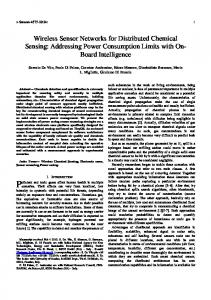
2 Recovery Unit In [1-2] a method called Iterative method is proposed to reduce the distortion. A block diagram of this method is shown in figure 1. In this figure, the G operator is all that is FM demodulator or PPM demodulator. The number of blocks in this figure is equal to the number of blocks. In reference [2] it’s shown that when number of iterations approach infinity, the distortion of signal reaches zero. In FM/PPM demodulation, G=PS, that S means sampling and P low pass filter therefore ith iteration output signal equals:
xi (t ) = λx 0 (t ) + (1 − λG ) x i −1 (t )
(1)
Filtering may be done using FFT or FIR methods. Besides, the constant λ can affect rate of improvement of signal and it can make the system unstable, if not selected properly. All of these effects are discussed in the following sections. V. Prasanna et al. (Eds.): DCOSS 2005, LNCS 3560, pp. 417 – 419, 2005. © Springer-Verlag Berlin Heidelberg 2005
418
M. Borhani and V. Sedghi
Fig. 1. Block diagram of iterative method
3 Simulation Results
Fig. 2. MSE as a function of number of blocks for different sampling rate for PPM(left) /FM (right)demodulator
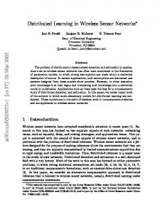
3.1 The Lambda effect FM Demodulator
PPM Demodulator
-15
-10
-20 -20 MSE
MSE
-25 -30
-30 -35
-40
-40 -45 25
-50 25 20
1.5
20
1.5 15
15 10
10
1
1 5
5 iteration
0.5
0.5
iteration
lambda
lambda
Fig. 3. The lambda effect for iterative method in PPM(left)/FM(right) demodulator
3.2. The Noise effect
σ 2 = −10
σ 2 = −10
σ 2 = −20 σ 2 = −20
σ 2 = −30
σ 2 = −30
σ 2 = −40 σ 2 = −40
Fig. 4. The noise effect on iterative method for PPM(left)/FM(right) demodulator
Distributed Recovery Units for Demodulation in Wireless Sensor Networks
419
4 Conclusions In this paper, we examined iterative method for demodulation of FM and PPM signals. Our simulations proved that, the method is strongly capable to reconstruct the message signal. One can see that, the amount of distortion decreases as the number of blocks increases in FM and PPM demodulators. Two schemes for filtering are considered and the effect of choosing lambda is studied in both FM and PPM demodulators. We see that iterative method is very sensitive to input noise and its performance degrades a great amount when the noise is presented at the input. Acknowledgement. With Great thanks from Dr. F.A. Marvasti.
References [1] F. Marvasti, A Unified Approach to Zero-Crossing and Nonuniform Sampling of Single and Multidimensional Signals and Systems, Nonuniform Publication, 1987. [2] F. Marvasti, "The reconstruction of a signal from the FM zero-crossing", Trans. of IECE of Japan, vol. E68, no. 10, Oct. 1985.