2005 IEEE/RSJ International Conference on Intelligent Robots and Systems
Distributed Visual Servoing: A Cross-Platform Agent-based Implementation∗ Enric Cervera Laboratory of Robotic Intelligence Jaume-I University Campus Riu Sec, 12071 Castell´o, Spain
[email protected]
Abstract— Visual control tasks demand very fast processing and transfer of huge amounts of data —live video images. Nowadays, computers and communication systems have become powerful enough to allow more flexible implementations of visual control tasks, enlarging the field of application to embrace networked systems, e.g. cooperative robots or mobile manipulators. In such setups, video grabbing, vision processing, and control might be located in different platforms across the network. This paper presents a cross-platform, networked implementation of visual control tasks based on software agents and video streaming technologies. This implementation consists of free, off-the-shelf, software components, resulting in a transparent system whose configuration can be adapted to existing hardware in very different ways, without any modification in the source code. We present several configurations which span onboard and offboard camera setups, and we experimentally determine the control loop delay of a real system, to test the feasibility of the proposed approach. Index Terms— Networked robotics, visual servoing, distributed systems, video streaming.
I. I NTRODUCTION Cooperative robotics and mobile manipulators pose new challenges to visual control systems. Classically, the camera and the controlled device are linked through fast data paths to the computing engine. Despite such a tight integration, visual feedback delay can drive a high bandwidth visual servoing system unstable [28]. In multirobot setups, cameras may not be directly linked to the robot, not even to the visual processing machine. Instead, communication through wired or wireless networks is more likely, even for video signals. This paper presents a networked model for visually controlled tasks. The goal is to identify the different parts in the control loop which may be isolated in different platforms, linked through a network. We emphasize the free availability of the selected software components, and the use of open standards. In order to demonstrate the feasibility of such implementation, we carry out an experimental measurement of the delay of the visual communication and processing steps, achieving live video frame rates (25 fps). ∗ This work is partially supported by the Spanish Ministry of Education and Science and by the Generalitat Valenciana.
0-7803-8912-3/05/$20.00 ©2005 IEEE.
3676
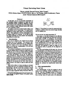
Fig. 1. Statement of the problem: the manipulation task is observed by several vision systems on different robots, connected through a wireless ethernet network.
Visual feedback has been used in teleoperion from their very beginning [7]. In order to obtain live video feedback, systems have evolved from refreshing static images via FTP or HTTP protocols to specialized real-time transfer protocols for audio and video (RTP). Most modern telerobotics systems use this protocol for remote monitoring [4], [15], [19], [25] but there are very few implemented networked visual control loops [9], [21]. Visual servoing has been previously used in teleoperated systems, though using a shared control, consisting in a combination of operator commands and a local autonomous visual servo controller [5]. The proposed implementation relies on the use of a crossplatform language (Java) [13] and an agent architecture [6], [12]. Both techniques have been widely used before in robotic applications [1], [3], [8], [19], [20], [22], [24]. Java has strong network features, and agents are a well-established distributed software paradigm. The contribution of this paper consists of a complete implementation of a networked visual control loop. Section II presents the software model, including an overview of the technologies involved. A classification of networked visual control systems is proposed in Section III. The feasibility of
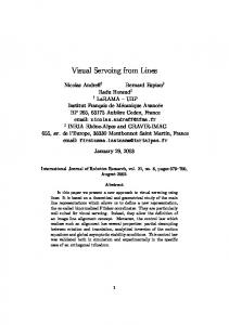
Fig. 2.
Distributed agent-based modelling of a visual control task.
the proposed approach, in a Local Area Network (LAN) is demonstrated in Section IV, by experimentally measuring the delay of the control loop. Finally, Section V summarizes the conclusions and future work. II. D ISTRIBUTED VISUAL CONTROL MODEL In a typical visual control task, the control loop consists of one or several cameras, the vision processing system, the control law, and the controlled device (a robot arm or mobile platform) [10]. We propose a distributed model —the ACV model— which splits the processing steps into three independent agents: Arm, Control, and Vision (see Fig. 2). As an option, a fourth agent —the video transmitter— can also be used, if the capturing step needs to be separated from the vision processing agent. Distributing the control loop among different tasks has the major advantage of increasing the available computing power, since vision and control processing can be performed simultaneously on different platforms. There is no free lunch, though: an additional communication delay is unavoidably introduced in the control loop. It should be noted that this agent-based implementation is completely transparent, thus not a single line in the source code of the agents needs to be modified to run the system locally or remotely, on two or even three different computers, as will be presented later. In addition, the choice of technologies allows a crossplatform implementation, which is capable of running without modification in a wide variety of computers and operating systems (Windows, Linux, Solaris, Mac, ...). A. Agent roles in the ACV model The purpose of each agent, and the communication links among them, are presented in the following: 1) Arm agent: The arm agent runs on the computer where the arm is physically installed and takes care of the low-level interaction with the robot controller. In the presented setup, this agent receives motion commands from the control agent and executes them on the arm. 2) Control agent: The control agent receives the visual information extracted from the images by the vision agent. The control law is then applied, resulting in a velocity command that is sent to the arm.
3677
3) Vision agent: This agent receives the video signal and processes the visual information, obtaining a set of visual features for each video frame. The vision agent will then send the visual features to the control agent. 4) Video transmitter: Optionally, video capturing can be splitted from vision processing, thus introducing a fourth agent, which sends a compressed video stream to the vision agent. In such case, some extra computing power is introduced for compressing and decompressing the video signal, and the communication delay is significantly increased with the video stream transmission. This option should be considered, though, if the camera platform cannot carry out the vision processing phase. The available technologies allow the vision agent to transparently manage either local or remote video sources, thus no modification in its source code is necessary, as will be seen in the following. B. Technologies used in the implementation 1) Java: Java [13] is an object-oriented cross-platform programming language with powerful networking capabilities. Any Java application can easily be delivered over the Internet, or any network, without operating system or hardware platform compatibility issues. Java has become in the last decade the language of reference for most networked robotic platforms and teleoperated systems [1], [3], [8], [19], [22], [24]. Java is able to operate with any robot and camera hardware via an interface to native C/C++ libraries, the Java Native Interface (JNI) [16]. The Java Media Framework API (JMF) [14] is an extension which enables audio, video and other time-based media to be added to applications and applets built on Java technology. JMF has already been used in robotic platforms, but only for monitoring [1], [18], [26]; the novelty of this paper relies on the use of JMF in a closed visual control loop. 2) Agents: Agents have been widely applied in robotics in the last decade [17], [27], even in vision-based tasks [2], [11], [23], though, to our knowledge, there has been no previous applications that fully implement real-time visual control tasks. Most agent platforms are implemented in the Java language, because of its networking capabilities. The visual control model presented in this paper is implemented according to the specifications provided by the Foundation for Intelligent Physical Agents (FIPA) [6]. Among the available platforms which follow such specifications, the Jade (Java Agent Development Framework [12]) platform was chosen due to its reliability, robustness, performance, availability, and supporting community. A Jade platform consists of one or more networked hosts; one of them is the main container, which holds some special system agents (e.g. a Yellow Pages agent, as explained below); the rest are just containers and they only hold application agents. All the containers must register with the main container upon starting, prior to agent launching.
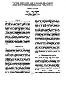
Fig. 3.
The AVC Model: dynamic interaction among agents.
3) RTP video streaming: Video feedback in early teleoperation environments consisted of static images which were refreshed periodically by the client browser, by using HTTP or FTP protocols, which in turn rely on the well-known Internetstandard TCP/IP protocol. Those protocols are designed for reliable communication at the expense of performance. To achieve real-time video transmission, the RTP protocol was proposed, relying on the UDP/IP protocol. Most modern telerobotics systems use this protocol for remote monitoring [4], [15], [19], [25]; our work moves a step forward, by processing the RTP video stream to extract the features of visual control tasks at live video rate (25 fps). C. Interaction model Agents can be regarded as independent software entities, which execute on different computers linked by a network, and which communicate by exchanging messages. FIPA specifications define a system agent: the DF (Directory Facilitator). This is an agent which executes in the main container and it provides a Yellow Pages service by means of which an agent can find agents in any other container with the services that it requires to achieve its goals. The FIPA specification defines a set of interaction protocols (registration, search, subscription, request, inform) [6], upon which the dynamic interaction among the agents of the AVC model is defined. Fig. 3 depicts such interaction model, as explained in the following. Upon start, the arm and vision agents must register with the DF agent, in order to offer their services to the rest of the agents of the system. The control agent asks the DF to find the agents —transparently in any registered container—, thus becoming able to communicate directly with them, regardless they execute on the same computer (container) or in any other one across the network. It then sends a subscription message to the vision agent, and waits for incoming visual features. Subscription is a FIPA interaction protocol which allows the control agent (the Initiator) to send a subscribe message to the vision agent (the Participant) indicating its desired subscription. The vision agent communicates subsequently
3678
all content matching the subscriptions condition using an inform-result, i.e. an inform communicative act with a result predicate as content. The vision agent continues to send inform-results until either the control agent cancels, communicated by sending a cancel message, or the vision agent experiences a failure, communicated with a failure message. The interaction between the control and arm agents is a request-inform protocol. This is similar to a remote procedure call, since the sender of a request message is indicating the receiver to perform and action. The result of such action is sent back in an inform message, which in general is used to communicate a fact to the receiver. Such interaction is repeated for each video frame, until an agent fails or the control agent detects a termination condition, e.g. the convergence to the desired image features. III. C LASSIFICATION OF DISTRIBUTED VISUAL CONTROL SYSTEMS
Splitting the visual control loops opens new possibilities for networked robots. Different configurations are available, though; in this section, a taxonomy is proposed, based on two criteria: • The location of the camera with respect to the arm. • The location of the vision agent with respect to the arm and control agents. Visual control systems typically use one of two configurations: onboard or offboard camera [10]. The first one is often referred to as eye-in-hand configuration, and the camera is mounted on the robot’s end-effector. The vision processing system is usually installed in the same computer which controls the robot. The second configuration has the camera installed anywhere else in the workspace, or in another robot. The vision capture system is running in a different computer from the one which controls the robot, but the processing system may be installed locally or remotely, since the image signal can be transmitted over the network. Figures 4-8 depict five possible configurations of the AVC model, which span those two categories, depending on the location of the camera, and the distribution of the agents among the different platforms. For the sake of simplicity, the arm and control agents will always be installed on the same computer, the one controlling the arm, thus the presented configurations differ in the location of the vision agent. Though some control laws may be computer intensive, the most demanding step of the loop is usually the vision processing phase. It must be noted that, in all five configurations, the software is exactly the same. This means that the source code of the agents is not changed: only the platforms need to be registered prior to execution, and the URL of the video source needs to be indicated accordingly to the vision agent. Moreover, the code runs without any modification on different
Fig. 4.
Onboard camera + local vision processing.
Fig. 8.
Offboard camera + vision processing on a third platform. TABLE I T ECHNICAL SPECIFICATIONS OF PLATFORMS .
Fig. 5.
Onboard camera + remote vision processing.
operating systems due to the cross-platform capabilities of the Java language. IV. E XPERIMENTAL TESTING Vision-based tasks are highly sensitive to the delay in the control loop. Some approaches cope with the delay in the loop to define stability limits [28], but an estimation of the time delay is required. In this section we present experimental results of delay measurement for all the distributed configurations. In our setup, a Mitsubishi PA-10 robot arm is mounted on a mobile base (not used in the experiment), and both are controlled from an onboard computer. An IEEE-1394 camera is mounted on the end-effector of the arm. Onboard and offboard configurations are distinguished by simply connecting the camera either to the onboard computer or to
Fig. 6.
Fig. 7.
Offboard camera + vision processing on the camera platform.
Offboard camera + vision processing on the robot platform.
3679
Host
CPU(s)
L2 Cache
Bus Speed
Main Container
Athlon 1.7 GHz
256 KB
133 MHz
Container-1
Pentium-IV 3 GHz
512 KB
400 MHz
Container-2
2 × Xeon 2.8 GHz
512 KB
533 MHz
an external one. The robot host is the main container, and two more hosts are used: the one holding the camera in offboard configurations (container-1), and a third computer (container-2). The three computers are linked together into a 10 Mbps wired Ethernet LAN. Table I summarizes the technical specifications1 of the computers, which must be considered prior to drawing any conclusion from the time delay analysis. As can be seen, the robot host is less powerful than the external computers, since it cannot be expanded easily. The camera observes an object lying in a plane parallel to the image plane, while the arm moves in a sinusoidal trajectory. The position of the arm is tracked periodically and logged, together with the system time (in milliseconds). The visual feature vector consists of the coordinates of the centroid of the segmented blob. After processing an image, the vision agent sends a message with such content to the control agent. In all the experiments, a sustained video rate of 25 fps was achieved. The time stamp of the vision signal is recorded when the feature vector arrives to the control agent. In order for time data to be synchronized, both the arm agent and the control agent run on the same computer, the one attached to the arm. Prior to the measurement of phase delay, signals are normalized, resulting in sinusoidals of equal amplitude. The delay is measured at zero crossings, where signals are mostly linear, the actual crossing being determined by the interpolation between the corresponding points (Fig. 9). The median of nine runs for each configuration is compared in Table II. Not surprisingly, the use of video streaming increases the delay, as much as 36 ms onboard, and 50-57 ms offboard. Such streaming is the most demanding communication task, since video frames are compressed, transferred across the network, and decompressed again. On the other 1 Main
memory (RAM) is the same, 512 MB on each computer.
Arm position Visual feature
1
Normalized units
0.5
0
−0.5
−1 8.5
9
Fig. 9.
9.5
10 Time (s)
10.5
11
Detail of logged signals.
hand, onboard and offboard configurations with local vision processing are pretty much the same, thus implying that messages between agents do not have significant impact on delay. Finally, offboard processing with three hosts is slightly faster than with only two; the reason being that the savings in computing time by a more powerful computer compensates the extra transmission time. TABLE II E XPERIMENTAL DELAY RESULTS Camera mount Onboard
Offboard
Vision Agent
Delay (ms)
Local
106
Remote
142
On camera host
107
On robot host
164
On third host
157
A classification of distributed visual tasks is proposed, depending on the physical and logical distribution of the elements, and the advantages and drawbacks of each configuration is sketched. Finally, experimental testing has been carried out to determine the feasibility of the proposed approach on a real system, achieving 25 fps video processing. Such tests illustrate the problem of time delay, and its consequences, including divergence of the control system. Such delay is caused by the video streaming process; thus, local image processing and communication among agents is the best solution for distributed control. The confluence of networked robotics and visual control opens endless possibilities for new setups involving mobile robots, onboard or offboard cameras, and mobile Internet devices (laptops, PDAs, mobile phones). The work presented so far has used only unicast, i.e., oneto-one video streaming. Multicast, one-to-many, streaming is also possible, thus the video signal would be sent to several computers which could perform parallel visual processing. An even more flexible approach should include a streaming server, which would gather the video sources and serve video streams to any number of clients; the delay problem could become severe, though, and more testing is needed. Another interesting extension will consist of the implementation of a proxy agent, which will enable the transmission of message agents through sockets, thus allowing the interaction with standard browsers and the WWW. More powerful vision processing is under implementation, to perform more complex tasks, and to fully exploit the benefits of using more capable computers, despite the added communication delays. ACKNOWLEDGMENT
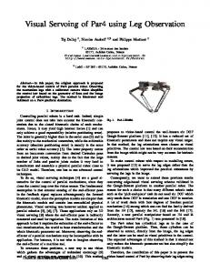
In order to confirm the influence of time delay in system stability, a simple, 1 DOF visual servoing experiment has been carried out: Fig. 10 depicts the image pixel error of the control task for local and remote onboard configurations. In this setup, remote processing has increased the loop delay in approximately 34% (106 - 142 ms), resulting in divergence when using high gains. In order to avoid such increase in delay, video streaming should be avoided, if possible; thus, local image processing and communication among agents is the best solution for distributed control. V. C ONCLUSIONS This paper has presented a distributed model for visual control tasks. This model is flexible enough to allow the execution of its components (agents) in different computers, without need to modify the source code. The implementation relies on off-the-shelf software, and open standards. Another benefit is the ability to run untouched on different computers and operating systems (cross-platform).
3680
Thanks to Gael Saint-Luc and Benjamin Berton for their contribution in the implementation. R EFERENCES [1] H. M. Barbera, M. A. Z. Izquierdo, and A. F. G. Skarmeta. Webbased supervisory control of mobile robots. In Proc. of the IEEE Int. Workshop on Robot and Human Interactive Communication, pages 256–261, 2001. [2] A. Chella, S. Vitabile, and R. Sorbello. A vision agent for mobile robot navigation in time-variable environments. In Proc. of the Int. Conf. on Image Analysis and Processing, pages 559–564, 2001. [3] Q. Chen, H. Geng, and P.-Y. Woo. Research on and pure Java realization of a web-based mobile robot system. In Proc. of the American Control Conf., volume 1, pages 615–620, 2003. [4] I. Elhajj, J. Tan, Y. Sun, and N. Xi. Supermedia enhanced human/machine cooperative control of robot formations. In Proc. of the IEEE/RSJ Int. Conf. on Intelligent Robots and Systems, volume 2, pages 1296–1301, 2002. [5] S. Ethier, W. J. Wilson, and C. Hulls. Telerobotic part assembly with shared visual servo control. In Proc. of the IEEE Int. Conf. on Robotics and Automation, pages 3763–3768, 2002. [6] http://www.fipa.org. [7] K. Goldberg and R. Siegwart, editors. Beyond Webcams: An Introduction to Online Robots. The MIT Press, 2001.
Initial gain × 2
Initial gain 100
60
40
40
20
20
20
−20
Pixel error
60
40
0
0 −20
0 −20
−40
−40
−40
−60
−60
−60
−80
−80
−80
−100
−100
−100
0
1
2
3
4
5
0
1
2
3
4
5
Initial gain × 4
Initial gain × 5
2
20
20
Pixel error
40
20
Pixel error
60
40
0 −20
0
−40
−40
−60
−60
−60
−80
−80
−80
−100
−100
−100
4
5
0
1
2
Time (s)
Fig. 10.
3
4
Remote Local
−20
−40
3
5
Initial gain × 6
60
−20
4
80
40
0
3
100 Remote Local
80
60
2
1
Time (s)
100 Remote Local
80
1
0
Time (s)
100
0
Remote Local
80
60
Pixel error
Pixel error
100 Remote Local
80
Time (s)
Pixel error
Initial gain × 3
100 Remote Local
80
5
0
1
2
Time (s)
3
4
5
Time (s)
Pixel error for local and remote onboard configurations, with several gains.
[8] H. Hiraishi, H. Ohwada, and F. Mizoguchi. Web-based communication and control for multiagent robots. In Proc. of the IEEE/RSJ Int. Conf. on Intelligent Robots and Systems, volume 1, pages 120–125, 1998. [9] A. Hoover and B. D. Olsen. Path planning for mobile robots using a video camera network. In IEEE/ASME Int. Conf. on Adv. Intelligent Mechatronics, pages 890–895, 1999. [10] S. Hutchinson, G. D. Hager, and P. I. Corke. A tutorial on visual servo control. IEEE Transactions on Robotics and Automation, 12(5):651– 670, 1996. [11] H. Ishiguro, K. Kato, and S. Tsuji. Multiple vision agents navigating a mobile robot in a real world. In Proc. of the IEEE Int. Conf. on Robotics and Automation, volume 1, pages 772–777, 1993. [12] http://jade.tilab.com. [13] http://java.sun.com. [14] http://java.sun.com/products/java-media/jmf/. [15] J.-W. Kim, B.-D. Choi, S.-H. Park, K.-K. Kim, and S.-J. Ko. Remote control system using real-time MPEG-4 streaming technology for mobile robot. In Proc. of the Int. Conf. on Consumer Electronics, pages 200–201, 2002. [16] S. Liang. The Java Native Interface: Programmer’s Guide and Specification. Addison-Wesley, 1999. [17] W. Lim. An agent-based approach for programming mobile robots. In Proc. of the IEEE Int. Conf. on Robotics and Automation, volume 4, pages 3584–3589, 1994. [18] C. Ling, T. Min, and C. Gen-Cai. Using Java technology to realize web-based multimedia system. In Proc. of the Int. Conf. on Signal Processing, volume 2, pages 989–993, 2002. [19] F. Monteiro, P. Rocha, P. Menezes, A. Silva, and J. Dias. Teleoperating a mobile robot. a solution based on Java language. In Proc. of the IEEE Int. Sym. on Industrial Electronics, pages 263–267, 1997.
3681
[20] P. Nebot, G. Saintluc, B. Berton, and E. Cervera. Agent-based software integration for a mobile manipulator. In Proc. of the IEEE Int. Conf. on Systems, Man and Cybernetics, pages 6167–6172, 2004. [21] R. Rao, V. Kumar, and C. J. Taylor. Experiments in robot control from uncalibrated overhead imagery. In Int. Sym. on Experimental Robotics (ISER), 2004. [22] A. S. Sekmen, Z. Bingul, V. Hombal, and S. Zein-Sabatto. Humanrobot interaction over the Internet. In Proc. of the IEEE Southeastcon, pages 223–228, 2000. [23] K. Terada, T. Nakamura, H. Takeda, and T. Ogasawara. Towards cognitive agents: Embodiment based object recognition for visionbased mobile agents. In Proc. of the IEEE/RSJ Int. Conf. on Intelligent Robots and Systems, volume 3, pages 2067–2072, 2000. [24] M. F. Vaida and L. Lazar. Intruder detection considering a Java platform application. In Proc. of the Int. Conf. on Information Technology Interfaces, volume 1, pages 449–452, 2002. [25] X. Xiaohui, D. Zhijiang, and S. Lining. The design and implementation of real-time Internet-based telerobotics. In Proc. of the IEEE/RSJ Int. Conf. on Intelligent Robots and Systems, volume 2, pages 815–819, 2003. [26] Y.-C. Yang and F.-T. Cheng. Autonomous and universal remote control scheme. In IEEE 28th Annual Conference of the Industrial Electronics Society, volume 3, pages 2266–2271, 2002. [27] F. Zanichelli, S. Caselli, A. Natali, and A. Omicini. A multi-agent framework and programming environment for autonomous robotics. In Proc. of the IEEE Int. Conf. on Robotics and Automation, volume 4, pages 3501–3507, 1994. [28] J. Zhang, R. Lumia, J. Wood, and G. Starr. Delay dependent stability limits in high performance real-time visual servoing systems. In Proc. of the IEEE/RSJ Int. Conf. on Intelligent Robots and Systems, pages 485–491, 2003.