is subtracted ledge = - xj+lr2. - Tedg,. All arithmetic is performed in 8 bits 2's complement. The original video stream is delayed to. 4 Trademark of Datacube Inc.
FOR iEPR6DE1''tDIbN PURPOSES
rr. ADA7
1
CU ENTATION PAGIE b
.
FE 2 T 1990
2&. SECURITY CLASSIFICATION AUTHO
3. DISTRIBUTIONIAVAILABIU"Y OF REPORT
-
EDU 13 4. PERFORMING ORGANIZATION REPORT NUMPER(Sa
.
2b. DECLASSIFICATION/DOWNGRADI
.
Approved for public release;
distribution unlimited. 5. MONITORING ORGANIZATION REPORT NUMBER(S)
6b. OFFICE SYMBOL
6a. NAME OF PERFORMING ORGANIZATION Center of Excellence in AlI
ESTRiC.TIVE MA .,NGS RI
7a. NAME OF MONITORING ORGANIZATION
Jae)
(ifad
University of Pennsylyania
U. S. Army Research Office
2M
7b. ADDRESS (City, State, and ZIP Code)
6r. ADDRESS (Oty, St.t, mW ZIP Code)
P. 0. Box 12211
Deot. of Computer & Information Science 200 S. 33rd Street Philadelphia, PA 19104-6389 Sb. OFFICE SYMBOL (f appkabe)
Ba. NAME OF FUNDING/SPONSORING ORANIZATIONJ
27709-2211
Research Triangle Park, NC
9. PROCUREMENT INSTRUMENT IDENTIFICATION NUMBER
U. S. Army Research Office 10. SOURCE OF FUNDING NUMBERS
27P Code) 8c. ADDRESS (City. S", namd
PROGRAM
•ELEMENT Box 12211 Research Triangle Park, NC
P.
0.
IPROJECT
NO.
IN.
.
ITASK
27709-2211
~
IWORK
UNIT NO. ACCESSION
11.TITLE (kncude Secwuty COafcaon)
Video-Rate Visual Servoing for Robots (MS-CIS-89-18) 12. PERSONAL AUTHOR(S) Peter I. Corke and Richard P. Paul 13b. TIME COVERED 13&. TYPE OF REPORT
S. PAGE COUNT 14. DATE OF REPORT (Year. Moth. Day) 14 February 1989 TO I FROM 16. SUPPLEMENTARY NOTATION The view, opinions and/or findings contained in this report are those
Interim Technical
of €he authqr($).and should not .be const u~d as an official De artment of the Army position, 17 FIELD
18. SUBJECT TERMS (Continue on rfwv
COSATI CODES SUB-ROUP GROUP
if nfctvnay and odenrfy by block number)
Robotics, Visual servoing 19. ABSTRACT (Commue on
rWevrif necftary and idernitfy by b0ock nenber)
----- 'T-his paper presents some preliminary experimental results in robotic visual servoing, utilizing a newly available hardware region-growing and moment-generation unit. A Unix-based workstation in conjunction with special purpose video processing hardware has been used to visually close the robot position loop at video field rate. 60Hz. The architecture and capabilities of the system are discussed. Performance of the closed-loop position control is investigated analytically and via step response tests, and experimental results are presented. Initial results are for
2 dimensional servoing, but extensions to 3 dimensional positioning are covered along with methods for monocular distance determination.
/
*.
J
|21. ABSTRACT SECURITY CLASSIFICATION
20 DISTRIBUTION/AVALA ILTY OF ABSTRACT C]UNCLASSIFIEDIJNUMITED
C1
SAME AS RPT
22a NAME OF RESPONSIBLE INDIVIDUAL
DD FORM 1473, s4MAR
,
OTIC USERS
Unclassified 22b. TELEPHONE (In cude Area CoWe)
43 APR Odton may be usd untl exhausted. All other editon are obsolete.
22- OFFICE SYMBOL
SECURITY CLASSIFICATION OF THIS PAGE
UNCLASSIFIED
-UK!
VERSITY of PENS YL.,VAN1A
>.~
VIDEO-RATE VISUAL SERVOING FOR ROBOTS Peter I. Corke and Richard P. Paul MS-oIS-89-1 8, GRASP LAB-176
Department of Computer and Information Science School of Engineering and Applied Science Philadelphia, PA 19104-6389
90 02 26 030
VIDEO-RATE VISUAL SERVOING FOR ROBOTS Peter 1.Corke and
Richard P. Paul MS-':1S-89-18, GRASP LAB-176
Department of Computer and Information Science School of Engineering and Applied Science University of Pennsylvania Philadelphia, PA 19104 February 1989
Acknowledgements: This work was supported in part by NSF IR184-10413-AO2, MCS-8219196-CER, CCR8716975, NSF/DCR grants 8501482, NSF/DMC 8512838, U.S. Army grants DAA29-84-K-0061, DAA29-84-9-0027, tAc-0-o C- o o (.
VIDEO-RATE VISUAL SERVOING FOR ROBOTS Peter I. Corke 1 Richard F. Pau! 2 1. Abstract This paper presents some preliminary experimental results in robotic visual servoing, utilizing a newly available hardware region-growing and moment-generation unit. A Unix-based workstation in conjunction with special purpose video processing hardware has been used to visually close the robot position loop at video field rate, 60Hz. The architecture and capabilities of the system are discussed. Performance of the closed-loop position control is investigated analytically and via step response tests, and experimental results are presented. Initial results are for 2 dimensional servoing, but extensions to 3 dimensional positioning are covered along with methods for monocular distance determination. Finally some limitations of the approach and areas for further work are covered. 2. Introduction This paper presents some preliminary experimental results in robotic visual servoing, utilizing an off-the-shelf hardware region-growing and moment-generation unit. This unit can process a binary scene, containing many regions, at video data rates and yields fundamental geometric parameters about each region. Such a device opens up many applications that were not previously possible due to the computational compl,.-, involved. The authors' aim was to develop a system capab: _ e at least frame rate (30Hz) analysis of video data * functioning with a non-trivial scene "determining object position as well as distance " following a moving or stationary target * functioning with a moving camera A priori knowledge of the target object's shape and dimensions is assumed. A non-trivial scene is one with a complex ba-kground (not a black backdrop) and in which illumination levels may change. In this paper a distinction is made between tracking, and visual servoing. Much of the tracking literature assumes slow motion, or stop-start motion. Visual servoing however treats the camera-processing subsystem as a sensor with its own inherent dynamics, which the closedloop position control must take into account. There are many approaches to segmenting a complex scene so as to locate a possibly moving object. A general discussion of motion detection schemes is presented in[l]. Perhaps the simplest approach is image differencing[21 in which the difference between consecutive frames eliminates all detail from the scene except the edges of moving objects. This approach will fail if the velocity of the object is too low to differentiate motion energy from sensor noise, or if the camera is moving, and some hybrid strategy is needed to initially locate a static object. Research Scientist, CSIRO Division of Manufacturing Technology, Melbourne, Australia. 2Professor, CIS Department, University of Pennsylvania, Philadelphia.
-1-
A more sophisticated approach is optical flow analysis[31 which yields a dense velocity vector field from spatio-temporal changes in pixel intensities. This analysis is computationally expensive, particularly the smoothing operation[41 and r6quires special processing hardware to implement in real time. Other problems include interpretation of the velocity field for general camera [notion with rotations[5] and sensitivity to camera noise[6]. The derived velocity field must still be segmented to separate background trom foreground. A related technique is based on feature matching, where features are generally corner points[7, 8], edges[9] or regions. The change in position of various feature points between scenes can be used to estimate the velocity of those points. However features such as comers or lines are a sparse representation of the scene, and it is difficult to relate those features to the objects of interest in the environment without complex world models. Sanderson[101 discusses visual servoing of robots and proposes a control scheme based on features extracted from the scene such as tace areas of polyhedra, but gives no detail of the vision processing required to obtain those features. Kabuka describes two segmentationless approaches. One[ 11] uses an adaptive control based on parameters derived from the entire scene, while[ 12] is based on Fourier phase difference between consecutive frames. Image segmentation is only the first step towards object tracking, the next problem is to identify the position of the regions within the scene, and must be done whether the input image repr: sents intensity, velocity or range data. One approach to object location is to use a pyramid decomposition[ 13] so as to reduce the complexity of the search problem. Others have used moment generation hardware to compute the centroid of an object within the scene at video data rates[14, 15, 16). This paper discusses a region feature -pproach; a harware unit performs segmentation of the intensity image to identify region features. The regions are then further investigated in software to identify the target, and tracking commands are then generated from its position. This approach is very general and works regardless of the state of motion of camera and target. The task of segmenting a complex scene in real time is not trivial, but is nevertheless the basis of this work. There is relatively little literature on visual servo implementations for robot position control. Many papers present only simulation results. Approaches to date could be classified as either stop-start (not dealt with here) or continuous. Hill and Park[17] describe a closed-loop position controller for a Unimate robot. They use binary image processing for speed, but also propose the use of structured lighting to reduce computational burden and to provide depth determination. Coulon and Nougaret[181 describe a digital video processing system for determining the location of one object within a processing window, and use this information for closed loop position control of an XY mechanism. They report a settling time of around 0.2s to a step demand... Kabuka[ 11] describes a two axis camera platform and image processor controlled using an IBM-PC/XT, and reports a minimum time of 30s to center on an object. Makhlin[19] discusses aspects of accuracy, tracking speed, and stability for a Unimate based visual servo system.
El
A number of related areas also require real-time visual object tracking. Gilbert[20] discusses
_
automatic object tracking cameras used for rocket tracking. Andersson[21] describes a pingpong playing robot that uses a real-time vision system to estimate ball trajectory for a subsequent paddle positioning planning algorithm. While the system described is not a closed-loop position
controller many of the principles and probletiu are the same.
Codes 1J ' ud/or w.
t
2...4
Special
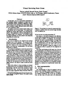
3. The experimental setup The experimental setup is shown schematically in. Figure 1. It comprises three major subsystems; robot controi, image processing, and coordination. 3.1. Robot control The robot control subsystem runs on a MicroVAX II connected to a Unimate Puma 560 robot and controller. Software on the MicroVAX can directly command rotut joint angles using the RCI interface of RCCL[22]. The MicroVk X in this application is programmea to L! - .:artesian rate server; that is, it accepts cartesian velocity commands (in the tool reference frame. over , Ethernet using Unix datagram facilities. The server program consists of two asynchronous processes, one that accepts cartesian rate command packets from the network, and another that communicates robot joint angle measurements and commands with the Unimate controller via the RCI software interface. The robot servo interval is currently 14 or 28ms[22]. The manipulator's inverse Jacobian is computed every sample period using the method of Paul and Zhang[23]. The desired robot joint angles are Limply calculated by
uVAX 2
Sun3/260
Unimate controller
MAXBOX
camera
m50{
Figure 1. Experimental setup.
-3-
ed,., =
0
d, +J 1 dXcliieu
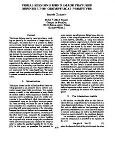
where dccie,w is the cartesian rate from the nlotin. client. The control algorithm makes no use of the observed joint angle Oobs since the robot is currently moving in free space, and it is the job of the Unimate servo subsystem to achieve desired joint angles. Cartesian rate data is transferred in Sun's external data representation, XDR, using UDP protocol. XDR is needed since the client process, running on a Sun-3, has a different data byte orientation and floating point representation to the MicroVAX. Benchmark tests indicate that writing a command packet on the client takes 1 100ps of elapsed time (kernel plus context switch time) using UDP, versus 2500p using TCP/IP. Although UDP is an inherently unreliable protocol, a,,, does not guarantee sequential delivery of packets, in the simple laboratory network environment these presented no problems. The server will accept datagrams from a number of different clients such as the visual tracker or a graphical teachpendant emulator. 3.2. Image processing 3.2.1. Segmentation Robust segmentation of a scene remains one of the great problems of machine vision. Hiralick[24] provides a survey of techniques applicable to static images. Unfortunately many of the algorithms proposed for segmenation are iterative and thus not suitable for real-time applications. This being the case most real-time implementations use contrived situations with dark backgrounds and simply threshold the video data. Much work has been done on automated approaches to threshold selection[25,26]. Many suggest that incorporating edge information into the segmentation process increases robustness. Although 2D histograms of edge and intensity information have been used to extract targets from noisy FLIR 3 imagery in real time[27, 28, 29], many approaches still use simple thresholding. An adaptive approach to segmentation is currently being investigated, using the capability of this hardware region-grower to perform many trial segmentations per second. One of the principle problems is how to rate the success of a segmentation so that an automatic system may modify or adapt its parameters[301. 3.2.2. Architecture for preprocessing A functional representation of the image processing subsystem is shown in Figure 2, and is based on Datacube 4 pipeline processing modules. As mentioned above, one design aim was that the system be able to function robustly with respect to different scenes, non-black background and changing lightlevels. The architecure described has attempted to meet these requirements within the constraints of modules available. The Datacube family of video processing modules are VMEbus boards that perform various operations on digital video data. The inter-module video data paths are patch cables installed by the user. The boards are controlled by a host computer via the VME bus. The video data paths run at lOMpixels/s and are known as MAXBUS4 . Horizontal and vertical timing is established
Forward looking infrared
-4.
Fhistogramming
(FEATUREMIA))
LUT
[sebcel
S
ledge
+
V t
V'FIRs
median
+
filter (SNAP)
LUT
delay Timae
r-----------------------------
host
deinterlacing (FRAMESTORE)
APA-512
-------------------------------
4
Figure 2. Image processing architecture.
by a separate timing bus linking all boards. All images are 512 x 512 pixels. The two VFIR convolution modules generate horizontal and vertical Sobel gradient components IX = GX
* lin
ly = Gy * lin
where GX and Gy are respectively the horizontal and vertical Sobel convolution kernels. A lookup iable is used to cott,,,:c :,; gradient magnitude, from which a gradient threshold, Tedge, is subtracted ledge =
j+lr2 x
- Tedg,
-
All arithmetic is performed in 8 bits 2's complement. The original video stream is delayed to 4 Trademark
of Datacube Inc.
-5-
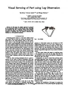
synchronize it with the thresholded cZ4 irnge, is offset by an intensity threshold Timage, and mapped through a lookup table which binarizes the pixels on the basis of both intensity and gradient magnitude. This provides some advantage in cases where regions of different intensity, but on the same side of the intensity threshold, separated, by distinct intensity gradients need to be resolved as separate regions. Binary median filtering on a 3x3 neighbourhood is used to eliminate single pixel noise regions which may overwhelm the region-growing unit. The Featuremax board is used to histogram edge and scene intensities periodically. The histogram data it computes is used by the host to select the thresholds Tedge and Ti,.age. For frame-rate processing the interlaced video data must be deinterlaced using double-buffered framestores in the Framestore module. Although only frame rate processing is discussed[31], an alternative approach which has been sucessfully tested is to process the interlaced data as two consecutive frames of half vertical resolution. The field processing approach has the advantage of eliminating the one frame time delay involved in deinterlacing, at the expense of twice as many regions to process per second. 3.2.3. APA-512 The APA-512[31] is a hardware unit designed to accelerate the computation of area parameters of objects in a scene. It was conceived and prototyped by the CSIRO Division of Manufacturing Tecbnology, Melbourne, Australia, in 1982-4, and is now manufactured by Vision Systems Ltd. ot Adelaide, Australia. The first author was a member of the lesign team. The unit has some similarities to other hardware implementations of binary image processing systems[15, 32, 16]. Andersson's unit[14] computes moments of grey-scale data so as to improve accuracy when dealing with a quickly moving object. However it has no capability to MAXBUS inutconnectivity
logic ALUs
Tll threshhold
Sinternal
frame buffer
_
address
blob
generator
hierarchy
bus [VME interface
VME bus Figure 3. APA-512 block diagram.
-6-
seed memory
detect and generate moments for multiple regions, and multiple regions will, if present, be merged into one moment set. The APA binarizes incoming video data and performs a single pass connectivity (simple-linkage region growing) analysis. The connectivity unit commands a bank of 8 ALUs which update the region parameters (referred to as seeds) stored in seed memory. The ALUs are implemented by custom gate arrays. The seed memory is dual ported to the host VMEbus so that seed parameters of completed regions may be read. The APA performs very effective data reduction, reducing a !OMpixel/s stream of grey-scale video data via a MAXBUS interface, to a stream of tokens representing objects in the scene. The host processor screens the tokens according to their parameters, and thus finds the objects of interest. For each region the following parameters are computed: ZIi, number of pixels (zeroth moment) Lic, Zy (first moments) a 2 , y 2, Jxy (second moments) minimum and maximum x and y values for the region perimeter length a perimeter point region color (0 or 1) window edge contact From these fundamental parameters, a number of commonly used area parameters such as area centroid location circularity macr and minor equivalent z'!ipse axis lengths object orientation (angle between major axis and horizontal) may be calculated by the host processor. The perimeter point is the coordinate of one pixel on the region's perimeter, and is used for those subsequent operations that require traversal of the perimeter. The edge contact flag, when set, indicates that the region touches the edge of the processing window and may be partially out of the image, in this case the parameters would not represent the complete object. Perimeter is computed by a sophisticated scheme that examines a 3x3 window around each perimeter point and produces an appropriate perimeter length contribution depending upon the slope of the perimeter at that point. Experiments reveal a perimeter error of less than 2% with this scheme. The APA-512 computes these parameters for each of up to 256 currentregions within the scene. Processing ui ihe data is d,:ne in raster scan fashion, and as the end of a region is detected the region label is placed in a queue and the host is notified by an interrupt or a pollable status flag. The host may read the region parameters and then return the region label to the APA for reuse later in the frame, thus allowing processing of more than 256 objects within one frame. This feature is essential for processing non-trivial scenes which can contain several hundred regions of which only a few are of interest. Maximum processing time is one video frame time. An additional feature of the APA is its ability to return region hierarchy information. When a region is complete the APA may be polled to recover the labels of already completed regions which were topologically contained within that region. This makes it possible to count the .7-
number of holes within an object, and compute the area of enclosed holes or internal perimeter. 3.3. Coordination The visual servoing is coordinated by a Sun-3/260 workstation running Sun's version of Unix, SunOS. Much of the processing involves sending commands to the various hardware image processing modules and this must be synchronzed with the video vertical blanking interval, which is only 1.2ms wide for RS-170 format video data. To achieve this reliably special device drivers are used, since a Unix process cannot guarantee the necessary response time. One driver was provided for the Datacube boards, and another was written for the APA. The main compuational burden is involved in post-processing regions detected by the APA. Small regions due to noise are screened out quickly and the region labels are returned to the APA. Larger regions are then screened according to object feature descriptions, which contain specifications for color (0 or 1), and permissible ranges for size, and shape. If a matching object is found then the manipulator's velocity in the 2D plane is set as a function of the displacement of the object's centroid from the center of the image. 4. Dynamic performance As menticned above, due to the high image processing rates attainable with this architecture, dynamic effects within the closed-loop system become significant. A block diagram of the control loop is shown in Figure 4, and where y is the robot position and it is the target position. The error e = y -u is computed in pixel space. The open-loop transfer function of the frame rate system is V (z) D (z)
Z-) R (z)
where the pole at z = I is due to the integrating effect of the cartesian rate server. Experiments reveal that delay is the dominant dynamic effect in this system, as has been found by others[ 17, 19, 101. The frame rate tracker exhibits 4 frames times of delay, whilst the field rate version exhibits 3 field times of delay. This can be accounted for by raster scan latencies. processing time, deinterlacing for the frame rate version, inter processor communictions and K o bs robot motion time. The vision processing transfer function is modelled as V (z)= Z-T-, where
,< -> e
V Iz )
D (z )
vision
compensator
R (z )
3 dz,
server
robot
Figure 4. Control system diagram (frame rate tracker).
-S-
is the observation gain in mm/pixel and is related to the calibration gains discussed below. We will ignore mechanica1 and servo dynamics of the robot and model it as a single sample time delay, R (z) . Thus the open-loop transfer function for the frame rate tracker is Kob,
Kobs
z (z-1)
This system is of type 1, and will thus exhibit steady state error for a constant velocity target. The simple compensator, D(z)=K z -a
introduces another pole at z = I to produce a type 2 system, while the zero is used to postion the closed-loop poles. The achievable closed-loop bandwidth of a discrete system is typically less than one fifth of the sample rate, or approximately 30rad/s in this case. 4.1. Step response tests The step response of the system was measured by a test rig with two spatially separated LEDs. only one of which was illuminated at a time. A manual switch controlled the LEDs and joint trajectory logging code in the robot server was activated by a change in the LEDs as sensed via an A/D converter channel.
.... 0.1 ......
.... .... ............ ........ .......... ................... ....
......................... 0 .0 8 ........ ....
...............-..
......... .................... ................... ................... .................... .. . 0 .0 6 .. ... y (rad) .... ...................... 0 .04 .....
. ..............................
0 .0 2 -.- ............... .................... ,.................... ................
.......... ......... . .. .
0 02
time ()
Figure 5. Measured closed-loop step response.
-9-
The compensator zero was located at . = 0.95, and a loop gait, of 0.12 was chosen. This yields dominant closed loop poles at z = 0.915+0.0619j, which yields a time to first peak of 1.3s with 1.5% overshoot. Figure 5 is the measured response of joint 2 of the robot, to a step applied at time 0. It can be seen that the measured response shows considerable overshoot, 36%, which is due to the action of the zero in the compensator. The simpl classical compensator is very sensitive to gain and compensator zero position, and performance is very far short of the potential bandwidth. Further work with state-feedback control and predictive state estimators is planned. 4.2. Control behaviour The controller described works well in practice, and has the advantage of being computationally inexpensive. The visual tracking process does not produce cartesian rate commands at a constant interval, occasionaliy skipping video frames when Unix schedules other processes to run. In practice this causes very little problem since the robot carries on at its previous velocity until another command is received. This strategy could also be used to follow a target moving, with low acceleration, that becomes temporarily obscured or merged with the background. S. Depth determination
A camera calibration is required to relate real world dimensions to those sensed by the camera in pixel space. Due to the aspect ratio of standard TV screens an image of a circle will appear as a vertically elongated ellipse in pixel space, thus two calibration constants KX and Ky are determined. These are defined such that at a distance u one pixel represents a rectangle of width Kx u and height Ky u. Many techniques for depth determination exist[33], and could perhaps be categorized as static, using cues such as lighting or texture, and triangulation based where multiple views from moving cameras or stereo camera pairs are interpreted. The technique outlined here is a simple static technique based on a priori knowledge of the target object's area. The area of a pixel is Apixel
=
2 KX Ky u
If the object of known area A, is determined by the APA to have N pixels then an estimate of the objects distance is Xest =
KAN
This simple technique works well in experiments, although factors such as focus and threshold may be expected to introduce errors. Further work using a continuous sequence of views from a moving camera has been commenced. 6. Further work and discussion The initial objective relating to non-trivial scenes has been only partially met. The system works well on a scene containing many regions but good constrast between target and background is still required. Motion blur effect in the camera has not been a problem due to the slow moving objects currently used. Experiments have shown that interlaced frames are substantially distorted due to the delay between exposure times of the component fields, but this problem is eliminated when -10-
working at field rate. Motion blur effects have been investigated in detail by Anderson[211 The development and execution of the visual tracker has been carried out under Unix on a workstation computer. Unix is an excellent environment for software development, and on a graphics workstation becomes a very powerful tool indeed. Unix is much maligned for its poor real-time performance, but in reality does an acceptable job. The particular machine used here with a 25MHz processor and 8Mbyte of memory, and with a single user did not page or swap processes. The only processes competing for the processor were the application and the periodic update daemon. Unix allows for rapid prototyping of software, and by placing the most response critical code in device drivers an acceptable level of performance was obtained for experimental purposes. This work, and others such as[21] show that video standards and conventional cameras are now a limiting factor in high performance video sensing applications. Video technology is currently tied to the needs of the television industrv where conflicting requirements such as small bandwidth and flicker have to lead to such devices as interlaced scanning. However when the end user is a machine vision system the requirements are very different. Fortunately, a new generation of cameras with both high resolution and high speed non-interlaced data formzts are becoming available. Areas for further work include: (1)
Determining the trajectory of target objects so that some attempt tc "ollow them through occlusion or background clutter can be made.
(2)
Investigation of more sophisticated control algorithms to improve the position respon.: time of the closed-loop system.
(3)
Investigate adaptive segmentation based on feedback of segmentation results from the APA so as to modify edge and scene thresholds.
7. Conclusion This paper has described a high performance image processing system capable of providing robot positioning commands at rates of up to 60Hz, and demonstrated closed-loop position control. The image processing subsection is comprised entirely of off-the-shelf components, notably a hardware region growing and moment generation unit. "-he region oriented approach used here enables the system to identify the target object whether or not there is relative motion between object and camera. 8. References 1.
W.N. Martin and J.K. Aggarwal, Survey. Dynamic Scene Analysis 1978.
2.
R. Jain, "Dynamic Scene Analysis Using Pixel-Based Processes," Computer 14(8) pp. 12-18 IEEE, (Aug 1981). B.K.P. Horn and B.G. Schunck, "Determining Optical Flow," Artificial Intelligence 17 pp. 185-203 (1981).
3. 4.
P. Anandan, "Measuring Visual Motion from Image Sequences," COINS 87-21 (Mar 87).
5.
A.M. Waxman and K. Wohn, "Contour Evolution, Neighborhood Deformation, and Global Image Flow: Planar Surfaces in Motion.," Inernational Journal of Robotics Research 4(3) pp. 95-108 (Fall 85). -11.
6.
D.W. Murray and B.F. Buxton, "Reconstructing the Optic Flow Field from Edge Motion: An examination of two different approaches.," First Conference on Artificial Intelligence Applications, pp. 382-388 IEEE, (Dec 84).
7.
W.B. Thompson and S.T. Barnard, "Lower-Level Estimation and Interpretation of Visual Motion," Computer 14(8) pp. 20-28 IEEE, (Aug 1981).
8.
H. Nagel, "Represenation of Moving Rigid Objects Based on Visual Observations," Computer 14(8) pp. 29-39 IEEE, (Aug 1981). C.L. Fennema and W.B. Thompson, "Velocity Determination in Scenes Containing Several Moving Objects," Computer Graphics and Image Processing 9 pp. 301-315 (1979).
9.
10. A.C. Sanderson, L.E. Weiss, and C.P. Neuman, "Dynamic Sensor-Based Control of Robots with Visual Feedback," IEEE Journal of Robotics and Automation RA-3(5) pp. 404-417 (Oct 1987). 11.
M. Kabuka, E. McVey, and P. Shironoshita, "An Adaptive Approach to Video Tracking," IEEE Journalof Robotics and Automation 4(2) pp. 228-236 (April 88).
12. M. Kabuka, J. Desoto, and J. Miranda, "Robot Vision Tracking System," IEEE Transactions on IndustrialElectronics 35(1) pp. 40-51 (Feb 88). 13.
C.H. Anderson, P.J. Burt, and G.S. van der Wal, "Change Detection and Tracking Using Pyramid Transform Techniques," Proceedingof SPIE 579 pp. 72-78 SPIE, (Sept 1985).
14.
R.L. Andersonn, "Real-Time Gray-Scale Video processing Using a Moment-Generating Chip," IEEE Journalof Robotics and Automation RA-1(2) pp. 79-85 (June 1985).
15.
P. Vuylsteke, P. Defraeye, A. Oosterlinck, and H. Van den Berghe, "Video Rate Recognition of Plane Objects," Sensor Review, pp. 132-135 (July 1981).
16. J.P. Froith, C. Eisenbarth, E. Enderle, H. Geisselmann, H. Ringschauser, and G. Zimmermann, "Real-time processing of binary images for industrial applications," pp. 61-168 in DigitalImage Processing Systems, ed. Z. Kulpa,Springer-Verlag, Germany (1981). 17.
J. Hill and W.T. Park, "Real Time Control of a Robot with a Mobile Camera," 9th InternationalSymposium on IndustrialRobots, SME, (Mar 13-15, 1979).
18. P.Y. Coulon and M. Nougaret, "Use of a TV camera system in closed-loop position control of mechnisms.," pp. 117-127 in International Trends in Manufacturing Technology ROBOT VISION, ed. Alan Pugh, 0. 19. A.G. Makhlin, "Stability and Sensitivity of Servo Vision Systems," Proc 5th Int Conf on Robot Vision and Sensory Controls - RoViSeC 5, pp. 79-89 IFS (Publications), (29-31 Oct, 1985). 20. A.L. Gilbert, "Video Data Conversion and Real-Time Tracking," Computer 14(8) pp. 50-56 IEEE, (Aug 1981). 21.
R.L. Andersonn, A Robot Ping-PongPlayer, MIT Press (1988).
22. John Lloyd, Implementation of a Robot Control Development Environment, McGill University (December 1985). 23.
R.P. Paul and Hong Zhang, "Computationally Efficient Kinematics for Manipulators with Spherical Wrists," InternationalJournal of Robotics Research 5(2) pp. 32-44 (Summer -12-
1986). 24. R.M. Haralick and L.G. Shapiro, "Survey. Image Segmentation Techniques," Computer Vision, Graphics,and Image Processing29 pp. 100-132 (1985). 25. Joan S. Weszka, "A Survey of Threshold Selection Techniques," Computer Graphics and Image Processing7 pp. 259-265 (1978). 26. P.K. Sahoo, S. Soltani, and A.K.C. Wong, "A Survey of Thresholding Techniques," Computer Vision, Graphics,and Image Processing41 pp. 233-260 (1988). 27. C.J. Samwell and G.A. Cain, "The BAe (BRACKNELL) Automatic Detection, Tracking and Classification System," 2nd Int.Conf. on Image Processing and Applications IEE265 pp 164-170 (JUne 1986). 28. O.R. Mitchell and S.M. Lutton, "Segmentation and Classification of Targets in FLIR Imagery," SPIE 155 pp. 83-90 (1978). 29. S. Cussons, "A Real-Time Operator for the Segmentation of Blobs in Imaging Sensors," Proc. lEE Electronic Image Processing Conference. 214 pp. 51-57 0. 30. Helen L. Anderson, Ruzena Bajcsy, and Max Mintz, "Adaptive Image Segmentation," MS-CIS-88-26, University of Pennsylvania (April 1988). 31.
APA-512MX Area ParameterAccelerator User ManualOct 87.
32. H. Tropf, H. Geisselmann, and J.P. Foith, "Some Applications of the Fast Vision System S.A.M.," Workshop on IndustrialApplications of Machine Vision Conf. Record, pp. 73-79 IEEE Computer Society, (May 3-5, 1982). 33. R.A. Jarvis, "A Perspective on Range Finding Techniques for Computer Vision," IEEE Transactions on Pattern Analysis and Machine Intelligence PAMI-5(2) pp. 122-139 (March 1983). 9. Acknowledgments This research was conducted at the General Robotics and Sensory Perception (GRASP) Laboratory, University of Pennsylvania. The authors are grateful to Vision Systems Ltd, Adelaide, Australia, for lending me the APA512 unit upon which this project is based. Professor Kwangyoen Wohn of the University of Pennsylvania provided advice and comments. Dr Bob Brown, Chief of the CSIRO Division of Manufacturing Technology, Melbourne Australia, made this visit to University of Pennsylvania possible.
-13-