This dissertation presents a domain-retargetable approach to reverse engineering based on end-user ...... goal is to provide an extensible hosting structure for tool integration and for the con- .... the best solution lies in a combination of the two.
Domain-Retargetable Reverse Engineering by
Scott Robert Tilley
B.Comp.Sci., Concordia University, 1986 M.Sc., University of Victoria, 1989 A dissertation submitted in partial ful llment of the requirements for the degree of DOCTOR OF PHILOSOPHY in the Department of Computer Science We accept this dissertation as conforming to the required standard Dr. H. A. Muller, Supervisor (Department of Computer Science) Dr. M. R. Levy, Departmental Member (Department of Computer Science) Dr. W. W. Wadge, Departmental Member (Department of Computer Science) Dr. V. K. Bhargava, Outside Member (Department of Electrical & Computer Engineering) Dr. P. G. Sorenson, External Examiner (University of Alberta)
c Scott Robert Tilley, 1995 University of Victoria
All rights reserved. This dissertation may not be reproduced in whole or in part, by photocopying or other means, without the permission of the author.
Supervisor: Dr. Hausi A. Muller
Abstract Understanding the structure of large information spaces can be enhanced using reverse engineering technologies. The understanding process is dependent on an individual's cognitive abilities and preferences, on one's familiarity with the application domain, and on the set of support facilities provided by the reverse engineering toolset. Unfortunately, most reverse engineering environments provide a xed palette of knowledge organization, data gathering, and information navigation, analysis, and presentation techniques. This dissertation presents a domain-retargetable approach to reverse engineering based on end-user programming. The approach enables users to model their application domain, to leverage their cognitive powers and domain knowledge, and to integrate other tools into the reverse engineering environment. It is supported by an architecture for a domainindependent meta reverse engineering environment, called the PHSE (P rogrammable H yper S tructure E ditor). The PHSE provides a basis upon which users construct domain-speci c reverse engineering environments. It is instantiated for a particular application domain by specializing its conceptual model, by extending its core functionality, and by personalizing its user interface. To illustrate the approach, a prototype implementation of the PHSE is retargeted to two application domains: online documentation and program understanding.
Keywords: Conceptual modeling, domain retargetability, end-user programming, hyper-
structure understanding, hypertext, integration mechanisms, online documentation, program understanding, reverse engineering, scripting.
ii
Examiners: Dr. H. A. Muller, Supervisor (Department of Computer Science) Dr. M. R. Levy, Departmental Member (Department of Computer Science) Dr. W. W. Wadge, Departmental Member (Department of Computer Science) Dr. V. K. Bhargava, Outside Member (Department of Electrical & Computer Engineering) Dr. P. G. Sorenson, External Examiner (University of Alberta)
iii
Contents Abstract
ii
Contents
iv
List of gures
ix
List of tables
xi
1 Introduction
1
1.1 1.2 1.3 1.4
The problem : : : : : : : : : The approach : : : : : : : : : Research objectives : : : : : : Related work : : : : : : : : : 1.4.1 The HAM : : : : : : : 1.4.2 HyperPro : : : : : : : 1.4.3 Rigi : : : : : : : : : : 1.4.4 The Software Re nery 1.4.5 PCTE Workbench : : 1.5 Dissertation outline : : : : : :
: : : : : : : : : :
: : : : : : : : : :
: : : : : : : : : :
: : : : : : : : : :
: : : : : : : : : :
: : : : : : : : : :
: : : : : : : : : :
: : : : : : : : : :
: : : : : : : : : :
: : : : : : : : : :
: : : : : : : : : :
: : : : : : : : : :
: : : : : : : : : :
: : : : : : : : : :
: : : : : : : : : :
: : : : : : : : : :
: : : : : : : : : :
: : : : : : : : : :
: : : : : : : : : :
: : : : : : : : : :
: : : : : : : : : :
: : : : : : : : : :
: : : : : : : : : :
: : : : : : : : : :
: : : : : : : : : :
: : : : : : : : : :
2 Programmable reverse engineering
2.1 Introduction : : : : : : : : : : : : : : : : : : : : : : : : : 2.2 A reverse engineering environment design space : : : : : 2.2.1 Cognitive models and the understanding process 2.2.2 Toolset extensibility : : : : : : : : : : : : : : : : iv
1 4 7 7 8 9 10 12 13 14
16 : : : :
: : : :
: : : :
: : : :
: : : :
: : : :
: : : :
: : : :
: : : :
: : : :
: : : :
16 17 18 19
2.2.2.1 Data gathering : : : : : : : : : : : : : : : : : : : : 2.2.2.2 Knowledge organization : : : : : : : : : : : : : : : 2.2.2.3 Information navigation, analysis, and presentation 2.2.3 Domain applicability : : : : : : : : : : : : : : : : : : : : : : 2.3 End-user programming : : : : : : : : : : : : : : : : : : : : : : : : : 2.3.1 End-user programmable applications : : : : : : : : : : : : : 2.3.1.1 Personal computer applications : : : : : : : : : : : 2.3.1.2 Text editors : : : : : : : : : : : : : : : : : : : : : 2.3.1.3 Operating systems : : : : : : : : : : : : : : : : : : 2.3.2 Scripting languages : : : : : : : : : : : : : : : : : : : : : : : 2.3.2.1 Tcl/Tk : : : : : : : : : : : : : : : : : : : : : : : : 2.3.2.2 HyperTalk and AppleScript : : : : : : : : : : : : : 2.3.2.3 Rexx : : : : : : : : : : : : : : : : : : : : : : : : : 2.3.3 Summary : : : : : : : : : : : : : : : : : : : : : : : : : : : : 2.4 Domain-retargetable reverse engineering : : : : : : : : : : : : : : : 2.5 Summary : : : : : : : : : : : : : : : : : : : : : : : : : : : : : : : :
: : : : : : : : : : : : : : : :
: : : : : : : : : : : : : : : :
: : : : : : : : : : : : : : : :
: : : : : : : : : : : : : : : :
: : : : : : : : : : : : : : : :
3 The PHSE
3.1 Introduction : : : : : : : : : : : : : : : : : : : : : : 3.2 Architecture : : : : : : : : : : : : : : : : : : : : : : 3.2.1 The kernel : : : : : : : : : : : : : : : : : : 3.2.2 The core : : : : : : : : : : : : : : : : : : : : 3.2.3 The interface ring : : : : : : : : : : : : : : 3.2.4 The personality ring : : : : : : : : : : : : : 3.2.5 Summary : : : : : : : : : : : : : : : : : : : 3.3 Model : : : : : : : : : : : : : : : : : : : : : : : : : 3.3.1 Telos: A language for conceptual modeling 3.3.1.1 The representational framework : 3.3.1.2 The classi cation dimension : : : 3.3.1.3 The generalization dimension : : : 3.3.1.4 The attribute mechanism : : : : : v
20 21 25 27 29 29 29 30 31 32 32 32 33 33 34 35
36 : : : : : : : : : : : : :
: : : : : : : : : : : : :
: : : : : : : : : : : : :
: : : : : : : : : : : : :
: : : : : : : : : : : : :
: : : : : : : : : : : : :
: : : : : : : : : : : : :
: : : : : : : : : : : : :
: : : : : : : : : : : : :
: : : : : : : : : : : : :
: : : : : : : : : : : : :
: : : : : : : : : : : : :
: : : : : : : : : : : : :
: : : : : : : : : : : : :
36 37 38 38 39 39 40 40 40 41 42 44 44
3.3.1.5 Rationale : : : : : : : : : : : : : : : : : : : : : 3.3.2 Conceptual model : : : : : : : : : : : : : : : : : : : : : 3.3.3 Data model : : : : : : : : : : : : : : : : : : : : : : : : : 3.4 Realization : : : : : : : : : : : : : : : : : : : : : : : : : : : : : 3.4.1 API : : : : : : : : : : : : : : : : : : : : : : : : : : : : : 3.4.2 Implementation : : : : : : : : : : : : : : : : : : : : : : : 3.4.2.1 Core functionality : : : : : : : : : : : : : : : : 3.4.2.2 User interface : : : : : : : : : : : : : : : : : : 3.4.2.3 Model : : : : : : : : : : : : : : : : : : : : : : : 3.4.3 Toolset : : : : : : : : : : : : : : : : : : : : : : : : : : : 3.4.3.1 Data gathering : : : : : : : : : : : : : : : : : : 3.4.3.2 Knowledge organization : : : : : : : : : : : : : 3.4.3.3 Information navigation, analysis, presentation 3.4.3.4 Miscellaneous operations : : : : : : : : : : : : 3.4.3.5 Remarks : : : : : : : : : : : : : : : : : : : : : 3.5 Summary : : : : : : : : : : : : : : : : : : : : : : : : : : : : : :
: : : : : : : : : : : : : : : :
: : : : : : : : : : : : : : : :
: : : : : : : : : : : : : : : :
: : : : : : : : : : : : : : : :
: : : : : : : : : : : : : : : :
: : : : : : : : : : : : : : : :
: : : : : : : : : : : : : : : :
4 Retargeting the PHSE
4.1 Introduction : : : : : : : : : : : : : : : : : : : : : : : : : : : : : : : 4.2 Instantiation : : : : : : : : : : : : : : : : : : : : : : : : : : : : : : 4.3 Online documentation : : : : : : : : : : : : : : : : : : : : : : : : : 4.3.1 Background : : : : : : : : : : : : : : : : : : : : : : : : : : : 4.3.2 The problem : : : : : : : : : : : : : : : : : : : : : : : : : : 4.3.3 The approach : : : : : : : : : : : : : : : : : : : : : : : : : : 4.3.4 An illustrative example : : : : : : : : : : : : : : : : : : : : 4.3.4.1 Knowledge organization : : : : : : : : : : : : : : : 4.3.4.2 Data gathering : : : : : : : : : : : : : : : : : : : : 4.3.4.3 Information navigation, analysis, and presentation 4.3.5 Summary : : : : : : : : : : : : : : : : : : : : : : : : : : : : 4.4 Program understanding : : : : : : : : : : : : : : : : : : : : : : : : 4.4.1 Background : : : : : : : : : : : : : : : : : : : : : : : : : : : vi
45 45 46 48 48 49 49 50 51 52 53 54 55 63 65 65
66 : : : : : : : : : : : : :
: : : : : : : : : : : : :
: : : : : : : : : : : : :
: : : : : : : : : : : : :
: : : : : : : : : : : : :
66 67 68 69 70 71 75 75 75 78 82 83 83
4.4.2 The problem : : : : : : : : : : : : : : : : : : : : : : : : : : 4.4.3 The approach : : : : : : : : : : : : : : : : : : : : : : : : : : 4.4.4 An illustrative example : : : : : : : : : : : : : : : : : : : : 4.4.4.1 Knowledge organization : : : : : : : : : : : : : : : 4.4.4.2 Data gathering : : : : : : : : : : : : : : : : : : : : 4.4.4.3 Information navigation, analysis, and presentation 4.4.5 Summary : : : : : : : : : : : : : : : : : : : : : : : : : : : : 4.5 Summary : : : : : : : : : : : : : : : : : : : : : : : : : : : : : : : :
: : : : : : : :
: : : : : : : :
: : : : : : : :
: : : : : : : :
5 Conclusions 5.1 5.2 5.3 5.4 5.5
Research summary : Contributions : : : : Results : : : : : : : : Future work : : : : : Concluding remarks
: : : : : : : :
98
: : : : :
: : : : :
: : : : :
: : : : :
: : : : :
: : : : :
: : : : :
: : : : :
: : : : :
: : : : :
: : : : :
: : : : :
: : : : :
: : : : :
: : : : :
: : : : :
: : : : :
: : : : :
: : : : :
: : : : :
: : : : :
: : : : :
: : : : :
: : : : :
: : : : :
: : : : :
: : : : :
: : : : :
: : : : :
: : : : :
: 98 : 99 : 100 : 101 : 103
A Selected implementation details
A.1 Architecture of Rigi IV : : : : : : : : : : : : : : : : : A.2 Changes to Rigi IV : : : : : : : : : : : : : : : : : : : A.2.1 Phase I: Making the editor programmable : : A.2.2 Phase II: Making the user interface tailorable A.2.3 Phase III: Incorporating a domain model : : A.3 Limitations : : : : : : : : : : : : : : : : : : : : : : :
B Telos schemas B.1 B.2 B.3
85 86 88 89 91 93 96 97
121 : : : : : :
: : : : : :
: : : : : :
: : : : : :
: : : : : :
: : : : : :
: : : : : :
: : : : : :
: : : : : :
: : : : : :
: : : : : :
: : : : : :
: : : : : :
121 122 123 124 126 127
128
PHSE schema : : : : : : : : : : : : : : : : : : : : : : : : : : : : : : : : : : : 130 LATEX schema : : : : : : : : : : : : : : : : : : : : : : : : : : : : : : : : : : : 131 PL/AS schema : : : : : : : : : : : : : : : : : : : : : : : : : : : : : : : : : : 134
vii
C RCL examples C.1 C.2 C.3 C.4 C.5 C.6
Web deletion : : : : : : : : : O�ine layout : : : : : : : : : LATEX-speci c node open : : : Hypertext complexity metrics Cyclomatic complexity metric SQL/DS decomposition : : :
137 : : : : : :
: : : : : :
: : : : : :
: : : : : :
viii
: : : : : :
: : : : : :
: : : : : :
: : : : : :
: : : : : :
: : : : : :
: : : : : :
: : : : : :
: : : : : :
: : : : : :
: : : : : :
: : : : : :
: : : : : :
: : : : : :
: : : : : :
: : : : : :
: : : : : :
: : : : : :
: : : : : :
: : : : : :
: : : : : :
: : : : : :
138 139 140 141 144 145
List of Figures 2.1 Reverse engineering environment design space : : : : : : : : : : : : : : : : :
18
3.1 3.2 3.3 3.4 3.5 3.6 3.7 3.8 3.9 3.10 3.11 3.12
The PHSE's ring architecture : : : : : : : : : : : The PHSE schema : : : : : : : : : : : : : : : : : The PHSE toolset : : : : : : : : : : : : : : : : : Displaying active RCL variables and procedures : A neighborhood : : : : : : : : : : : : : : : : : : : Attribute- and structure-based selection widgets Web edit widget : : : : : : : : : : : : : : : : : : Web splicing : : : : : : : : : : : : : : : : : : : : Web traversal widget : : : : : : : : : : : : : : : : Connectivity analysis of a neighborhood : : : : : Menu customization widget : : : : : : : : : : : : Widget customization : : : : : : : : : : : : : : :
: : : : : : : : : : : :
: : : : : : : : : : : :
: : : : : : : : : : : :
: : : : : : : : : : : :
: : : : : : : : : : : :
: : : : : : : : : : : :
: : : : : : : : : : : :
: : : : : : : : : : : :
: : : : : : : : : : : :
: : : : : : : : : : : :
: : : : : : : : : : : :
: : : : : : : : : : : :
38 46 52 54 55 57 58 59 60 61 63 64
4.1 4.2 4.3 4.4 4.5 4.6 4.7 4.8 4.9
Retargeting the PHSE : : : : : : : : : : : : : : : : : : : Document hyperstructure : : : : : : : : : : : : : : : : : LATEX schema : : : : : : : : : : : : : : : : : : : : : : : : Di�erent views of a LATEX document : : : : : : : : : : : Writing style violation : : : : : : : : : : : : : : : : : : : PL/AS schema : : : : : : : : : : : : : : : : : : : : : : : PL/AS structural feature extraction and normalization : Data coupling and call structures : : : : : : : : : : : : : Name-based subsystem decomposition : : : : : : : : : :
: : : : : : : : :
: : : : : : : : :
: : : : : : : : :
: : : : : : : : :
: : : : : : : : :
: : : : : : : : :
: : : : : : : : :
: : : : : : : : :
: : : : : : : : :
: : : : : : : : :
: : : : : : : : :
67 73 77 79 80 90 93 94 95
ix
: : : : : : : : : : : :
: : : : : : : : : : : :
: : : : : : : : : : : :
A.1 The Rigi IV environment's main components : : : : : : : : : : : : : : : : : 122 A.2 Extending rigiedit : : : : : : : : : : : : : : : : : : : : : : : : : : : : : : : : : 124 A.3 New rigiedit architecture : : : : : : : : : : : : : : : : : : : : : : : : : : : : : 125 B.1 Telos s-expression grammar : : : : : : : : : : : : : : : : : : : : : : : : : : : 129
x
List of Tables 3.1 Sample icons : : : : : : : : : : : : : : : : : : : : : : : : : : : : : : : : : : :
62
4.1 LATEX artifacts and their icons : : : : : : : : : : : : : : : : : : : : : : : : : 4.2 PL/AS artifacts and their icons : : : : : : : : : : : : : : : : : : : : : : : : : 4.3 PL/AS relations : : : : : : : : : : : : : : : : : : : : : : : : : : : : : : : : :
76 89 91
A.1 Rigiattr for COBOL : : : : : : : : : : : : : : : : : : : : : : : : : : : : : : : 126
xi
Acknowledgments I am grateful to my supervisor, Dr. Hausi Muller, for his guidance, support, and friendship throughout my graduate career. He has been a great source of inspiration and has provided me with an admirable role model. He has also created an excellent research environment without which I would not have been able to complete this work. My time spent at UVic would never have been so enjoyable without members of the Rigi group to spend it with. To Mike, Ken, Peggy, Mehmet, Brian, Dilian, and others: Thank you. Near and far, past and present, all have contributed to this research in some way. Faith and I will miss the friendship and family support of Richard and Margret. They made Victoria feel more like home for us. Our card games, Milles Bournes, and holiday dinners are not nished, just temporarily suspended until we return. I would like to thank my soccer teammates from The Dirty Bits intramural squads over the years. They provided me with much-needed relief from daily activities|especially when happy hour was no longer possible. Finally, I would like to express my gratitude to the IBM Software Solutions Toronto Laboratory, the IBM Centre for Advanced Studies, and the Science Council of British Columbia for their support.
xii
For Faith, and my parents.
\A deadline has a wonderful way of focusing the mind." | Professor Moriarty, Ship in a Bottle, Star Trek: The Next Generation.
xiii
Chapter 1
Introduction \The idea of providing a tailorable, con gurable, integrated project support environment which is customized as necessary for di�erent organizations, projects, and individuals is in reality a long way from current practice." | Brown et al., Principles of CASE Tool Integration [BCM+ 94].
1.1 The problem This dissertation addresses the challenges of applying reverse engineering technologies to the problem of understanding large information spaces. Speci cally, it deals with aiding hyperstructure understanding (HSU): identifying artifacts and understanding their structural relationships in complex information webs [Oss84]. HSU is an objective rather than a wellde ned process [OT94]. The pre x hyper is used to distinguish HSU from the in-the-small activity of understanding the internal structure of any single artifact; we are concerned with the analysis of overall system structure. When any entity increases in size by several orders of magnitude, it changes in nature as well as in size [Wal89]. When one attempts to understand a large body of information, the overall structure of the information space is just as important as the inner structure of 1
CHAPTER 1. INTRODUCTION
2
any single artifact|if not more so. This is especially true when the number of artifacts in the domain is much larger than the size of each artifact. Decomposition has long been recognized as a powerful tool for the analysis of large and complex systems. The technique of decomposing a system, studying the components, and then studying the interactions of those components has been used successfully in many areas of engineering and science [Cou85]. For example, in the software engineering domain, modularization is a technique used to manage complexity by decomposing a large problem into several smaller ones. It can lead to simpler system structure, but it is not a panacea. It can lead to a proliferation of small parts; so much so that it is di�cult to understand their inter-relationships [Par79]. Since good software engineering design suggests that modules be kept relatively small, the number of modules in a large system is signi cant [Lic86]. For instance, in a system of 500,000 lines, with roughly 200 lines per module, there would be 2,500 modules. This is an order of magnitude more than there are lines of code in each module. At this scale, the understanding problem goes beyond the algorithms and data structures of computation [SG92]. It moves into the realm of architecture and HSU: determining what modules comprise the system, how they are organized, and how they interact [SvdB93]. Reverse engineering technologies can be used to aid HSU. Although no standard de nition of reverse engineering exists, Chikofsky and Cross [CC90] provide a useful taxonomy. They state: Reverse engineering is the process of analyzing a subject system to identify the system's components and their inter-relationships, and to create representations of the system in another form or at higher levels of abstraction.
While the term \reverse engineering" is borrowed from hardware development, where it is usually applied to the process of discovering how other people's systems work, this de nition of reverse engineering is su�ciently broad so as to be applicable to many domains. For example, in software engineering the term is used to describe the process of discovering how
CHAPTER 1. INTRODUCTION
3
one's own systems work. It can also be applied to hypertext to mean the creation of online documentation from existing linear text. Reverse engineering is seen as an activity which does not change the subject system; it is a process of examination, not a process of change. It can facilitate the understanding process through the identi cation of artifacts, the discovery of their relationships, and the generation of abstractions. This process is dependent on one's cognitive abilities and preferences, on one's familiarity with the application domain, and on the set of support facilities provided by the reverse engineering environment. Unfortunately, most reverse engineering environments are builder-oriented, rather than user-oriented. They provide a xed palette of techniques, decided in advance by the environment's developers. This limits the e�ectiveness of reverse engineering for HSU in at least three ways: domain applicability, domain modeling, and domain-instance analysis. A domain is a problem area [DMR94]. An approach to reverse engineering, and the environment supporting the approach, must be exible so that it can be applied to diverse target domains. \Domains" in this sense is an over-burdened term. It includes di�erent application domains, such as database systems, health information systems, and online documentation systems; implementation domains, including the application's implementation language; and the reverse engineering domain, in which the user applies reverse engineering to the problem of HSU. A domain model is a representation that captures the structure and composition of elements within a domain [Tra94]. It may be constructed through domain analysis: the process of identifying, organizing, and representing the relevant information in a domain [Rol94]. A successful approach to reverse engineering must allow di�erent domain models to be speci ed for di�erent application domains. A domain model provides the user with a set of expected constructs to look for when analyzing a subject system. Moreover, the domain model acts as a schema for guiding the reverse engineering process and as a framework for organizing its results. Perhaps the most important aspect of a successful reverse engineering environment in
CHAPTER 1. INTRODUCTION
4
aiding users to understand the structure of particular problem instances in a speci c application domain is toolset extensibility. No rigid environment that provides a static suite of techniques for the basic reverse engineering operations of gathering, organizing, and presenting information will ever be suitable for all users in all domains. Users should be able to alter the way builtin operations work, to integrate other tools and applications that provide complementary functionality into the environment, and to write their own routines for these activities if they so desire. Regrettably, the attitude that seems prevalent to many tool builders is that \if programmers (users) would just learn to understand ... the way they ought to" (i.e., the way the tools work), the comprehension problem would be solved [vMV93]. Such a builder-oriented view is unsuitable for the analysis of large bodies of information [BH92]. Instead, the reverse engineering environment should be user-oriented: it should aid HSU by providing approaches, tools, and interfaces that support the user's natural process of understanding|not hinder it.
1.2 The approach Structural understanding is identi ed in [Nin89] as the second of four levels of understanding. The rst and lowest level of understanding is the implementation level, which examines individual artifacts. The third level is functional understanding, which examines the relationships between artifacts and their behavior. The fourth level is the domain level, which examines concepts speci c to the application domain. The degree of abstraction increases with each level. The current state-of-the-art in reverse engineering is such that aiding understanding at the implementation level is possible, and limited aid is available for the structural level; automated function- and domain-level understanding is extremely limited, if not impossible. However, even structural-level understanding is problematic when the number of artifacts and relationships in the information space becomes very large. Hence, the goal is to increase
CHAPTER 1. INTRODUCTION
5
the power of reverse engineering at the structural level, so that understanding at higher levels of abstraction will be possible. We propose a domain-retargetable approach to reverse engineering based on end-user programming. The approach classi es reverse engineering activities into three canonical areas: data gathering, knowledge organization, and information navigation, analysis, and presentation techniques. By making each of these activities end-user programmable, the capabilities of the environment are extensible. It enables users to model their application domain, to leverage their cognitive powers and domain knowledge, and to integrate other tools into the reverse engineering environment to extend its functionality and personalize its interface to suit their needs. The approach is meant to advance the state-of-the-art in reverse engineering by providing a more user-oriented environment than the current stateof-the-practice. The approach enables users to construct models of their application domain. The models are described using Telos [Myl91], a language for conceptual modeling. The domain model provides structuring and abstraction mechanisms that help reduce the complexity of the information space. The abstraction mechanisms aggregation, classi cation, and generalization, as well as the notion of a web, are the central concepts used in the approach for representing higher levels of abstraction. By enabling users to represent diverse application domains using a common representation, knowledge organization has been made end-user programmable. The approach enables users to leverage their cognitive abilities and domain expertise through the pervasive use of scripting. HSU takes place within the context of a speci c application domain. Each person has a di�erent technique, and no process or sequence should be imposed by the support environment. To a great extent, the techniques used depend on personal style, and to some extent, on the task at hand [Bro91]. An interpreted language based on Tcl [Ous94] is used to record and exploit users' reverse engineering techniques in scripts. Users can create libraries of domain-dependent reverse engineering strategies encoded as scripts. As their expertise in their application domain grows, so will
CHAPTER 1. INTRODUCTION
6
their library of scripts. The approach enables users to integrate other tools into the reverse engineering environment to extend its functionality using the same scripting mechanism. This extensibility includes both the environment's operations and its interface. Scripts are used for control, data, and presentation integration. By providing a programmable toolset, the environment's applicability is not limited to one domain. By providing a programmable interface, users can adapt the environment to their particular taste, while still maintaining a common \look and feel." The approach is supported by a software architecture for a domain-independent meta reverse engineering environment for HSU, called the PHSE1 (P rogrammable H yperS tructure E ditor). The PHSE architecture directly addresses the canonical reverse engineering activities identi ed by the approach. The PHSE model includes a domain-independent conceptual model for the representation and organization of the artifacts and relations of complex hyperstructures, a data model upon which the conceptual model is built, and a physical layer upon which the data model is implemented. Together, the PHSE architecture and model provide a basis upon which users construct domain-speci c reverse engineering environments. The PHSE is instantiated for a particular application domain by specializing its conceptual model, by extending its core functionality, and by providing an application-speci c user interface personality. The resultant system is one that is tailored to a speci c application domain. It supports the gathering of information artifacts from the subject system, the organization of these artifacts into user-de ned structures, and the navigation, analysis, and presentation of the resultant structures in a user-de nable manner. 1
Pronounced \fuzzy".
CHAPTER 1. INTRODUCTION
7
1.3 Research objectives The focus of this research is to investigate a domain-retargetable approach to reverse engineering that facilitates exploratory HSU through the use of end-user programming. We are not attempting to investigate speci c aspects of reverse engineering per se, for example, speci c decomposition and clustering algorithms for programming understanding. Rather, our main objective is to validate our thesis that by incorporating end-user programming into all key aspects of reverse engineering, HSU is improved in an identi able manner. Our goal in the design of the PHSE is to construct a framework for reverse engineering that supports the approach. We show how the framework addresses the criteria for a reverse engineering environment. We also show how the PHSE architecture addresses de ciencies in existing systems. Our goal in illustrating the use of the PHSE is to validate our thesis by demonstrating the viability of the approach in two real-world application domains [Har94]. By creating a proof-of-concept implementation of the PHSE we show that the PHSE is realizable. By re-targeting it to online documentation and program understanding we show that the PHSE is domain retargetable. By integrating instantiations of the PHSE with other tools we show its extensibility.
1.4 Related work In this section we review ve of the most important bodies of work related to our research: the Hypertext Abstract Machine (HAM) [CG88], HyperPro [ON93], Rigi2 [MOTU93], the Software Re nery [NM93], and PCTE Workbench [AHF93]. These systems were chosen because they are excellent examples of successful applications in their particular domain. Our work is built upon the strengths and ideas espoused by these systems. The extensive bibliography at the end of this dissertation complements this overview. We will focus on Rigi IV, the Rigi system circa 1992. The reason for this clari cation will become apparent in Chapter 3, where the implementation of the PHSE is discussed. 2
CHAPTER 1. INTRODUCTION
8
1.4.1 The HAM The HAM is a general-purpose, transaction-based server developed at Tektronix for hypertext storage. Hypertext has been described as a tool to enhance human cognitive abilities by allowing users to impose their own structure on information [Con87]. Although there is no standard de nition of hypertext in the current literature,3 it is generally accepted to be an approach to organizing online information in a network structure. The network is composed of nodes4 connected by links. Many of the essential notions of hypertext were rst contained in the descriptions of a memex, written by Vannevar Bush in 1945 [Bus45]: \A device in which an individual stores books, records, and communications, and which is mechanized so that it may be consulted with exceeding speed and exibility. It is an enlarged intimate supplement to memory." In most hypertext implementations, the nodes (and in some systems the network itself) are viewed and manipulated through an interactive browser and/or structure editor. The relationships between di�erent pieces of information are represented using links, which tie together two (or more) nodes. Among other things, links provide end users with a means of navigation among nodes. Links may point to an entire node, or they may be anchored to speci c points or regions within a node. Both nodes and links may be typed to allow for di�erent semantic interpretations of both node contents5 and link relations. Hypertext systems commonly allow the attachment of attributes to both nodes and links. Such attributes are usually simple name/value bindings. Together, the nodes and links form a hyperdocument. An important characteristic of hypertext is personalization and customizability of information navigation and presentation; this incorporates the idea The ISO 10744 international standard does de ne both hypertext and hypermedia in very broad terms. Nodes are sometimes called chunks, artifacts, or information objects. 5 Hypertext has a more contemporary counterpart known as hypermedia [GT94], which describes hypertext systems with nodes that support multimedia information types. Hypermedia is a generalization of the hypertext concept, and, like hypertext, there is no generally accepted de nition, except that it blends hypertext and multimedia. Most modern hypertext systems are, to varying degrees, hypermedia systems. Within a hypermedia system, nodes may contain graphics, sounds, and video in addition to text. Although the term \hypermedia" relegates the term \hypertext" to systems with text-only nodes, we use the term \hypertext" to refer to both text-only and multimedia systems. 3
4
CHAPTER 1. INTRODUCTION
9
of nonlinearity, since nonlinearity gives control of the order of traversal to the user [Ash94]. The HAM provides a general and exible data model based on graphs, which contain hierarchically organized contexts, nodes, links, and attributes. A graph is the highest-level HAM object; it contains one or more contexts. Contexts partition the data within a graph. Each context has one parent context, zero or more child contexts, and contains zero or more nodes and links. A node contains arbitrary data. Object semantics are provided through user-de ned attribute/value pairs, which can be attached to contexts, nodes, or links. Attribute/value pairs extend the power of hypertext by allowing the organization of nodes and links into subgraphs in a single context. Subsets of HAM objects may be extracted from large graphs using a ltering mechanism based on attribute predicates. The HAM's commands are partitioned into seven categories of operations for creating, modifying, and accessing its basic hypertext components. The HAM is somewhat unique in that since it is not a hypertext system by itself, but rather a general-purpose hypertext engine upon which other hypertext systems can be constructed, it can serve hypertext systems in di�erent domains. For example, it has been used to model Guide buttons [Gui86], Intermedia webs [YHMD88], and NoteCards FileBoxes [Hal88]. It has also been used internally at Tektronix to develop a hypertextbased CASE tool called Dynamic Design [Big88], and a hypertext-based CAD system called Neptune [DS86]. The HAM represents an important step in the development of hypertext systems due to its exible architecture. However, its simple graph model has since been superseded by more sophisticated databases that provide richer data modeling capabilities.
1.4.2 HyperPro Osterbye et al. at Aalborg University in Denmark have blended literate programming [Knu84] with hypertext, creating a hyperstructure programming environment. Their rst prototype hyperstructure environment was for CLOS (an object-oriented extension of Common Lisp) [Nor91], and their second was for Smalltalk [Ost93]. Based on this early work, they developed HyperPro: a generic, language-independent hypertext environment which
CHAPTER 1. INTRODUCTION
10
can be parameterized to support di�erent programming languages. The basic object in HyperPro is an entity, which can be either a link or a node (atomic or composite). All entities possess a set of attribute/value pairs. A set of node and link instances form a program network termed the hyperstructure. The layered architecture of HyperPro is divided into three components: a repository, a Smalltalk kernel for control integration, and a number of editors which are suitable front ends (including a graph editor and the Epoch text editor, a hypermedia enhancement of Gnu Emacs). HyperPro represents an important step in the evolution of hypertext systems due to its programmable nature. However, its focus is on literate programming, not hyperstructure understanding. Moreover, its dependency on Smalltalk limits its applicability.
1.4.3 Rigi Rigi6 is a system for analyzing evolving software systems through reverse engineering. The main goal of the Rigi project is to extract abstractions from software representations and transfer this information into the minds of software engineers for software evolution purposes. The focus is on summarizing, querying, representing, visualizing, and evaluating the structure of large, evolving software systems. Rigi is composed of three major subsystems: a parser (rigireverse) for selected common programming languages of legacy software systems; a repository manager (rigiserver) that stores the information extracted from the source code using the GRAS database [KSW93]; and an interactive graph editor (rigiedit) that permits graphical manipulation of source code representations [MK88]. In the Rigi approach to software reverse engineering, the rst phase of the process|the extraction of software artifacts|is automatic and languagedependent; it essentially involves parsing of the subject system and storing the artifacts in a repository. The second phase is semi-automatic and features language-independent subsystem composition methods that generate hierarchies of subsystems [MU90]. 6
Rigi, pronounced \riggy," is named after a mountain in central Switzerland.
CHAPTER 1. INTRODUCTION
11
Subsystem composition is the process of constructing composite software components out of building blocks such as variables, procedures, and subsystems. Software quality criteria and measures based on exact interfaces and established software engineering principles such as low coupling and strong cohesion [Mye75] were formulated to evaluate the resultant subsystem structures [Mul90, MC91]. Using these subsystem composition facilities, which are supported by the graph editor, software structures such as call graphs, module graphs, and dependency graphs can be summarized, analyzed, and optimized according to software engineering principles. Rigi has been used in the discovery, reconstruction, and evaluation of subsystem structures in existing software systems [OMT92, MOTU93]; in the investigation of spatial and visual relationships among software artifacts for program understanding [MTO+ 92]; to support a documentation strategy using up-to-date views7 [TMO92]; in an evaluation of the use of structural views to support project management [Til92, TM93]; and as a test bed to gain better understanding of the use of reverse engineering technologies for program understanding [MTW93]. It has proven itself successful and has attracted much attention during demonstrations at several software engineering conferences around the world. However, by 1992, some of its shortcomings were becoming apparent. The operations provided by Rigi's graph editor are rich because of parameterization, but the total set is xed. The implicit assumption within the editor is that the user is reverse engineering an application written in one of the imperative, procedural programming languages commonly used in legacy software systems, such as C or COBOL; the target language must t the Rigi model [Mul86]. Consequently, the operations are geared toward coupling and cohesion as the guiding measurements used when selecting components to be collapsed into a subsystem. The selection operations depend strongly on client/supplier relationships. Moreover, the editor provides just a single abstraction mechanism for coping with complexity: hierarchies formed through recursive aggregation. A further restriction is A view represents a particular state and display of a software model. Di�erent views of the same software model can be used to address a variety of target audiences and applications. The Rigi notion of a views is similar to that provided by the Improv spreadsheet [Imp91]. 7
CHAPTER 1. INTRODUCTION
12
placed on the topology of the resultant subsystem compositions: they must be (k; 2)-partite graphs|a class of layered graphs [EMM90]. This restriction was imposed to provide a structuring mechanism to support navigation [Mul89], but its forced presence is not always appropriate. The graph editor operations are language-independent, which is both an advantage and a detriment. It is an advantage, since it means a single tool will work for systems written in most imperative programming languages. It is a detriment because it means domain knowledge is lost. Finally, the graph editor is completely graphical; it does not provide any mechanism for automated command processing. Such an interface paradigm does not scale up well when one is dealing with graphs that represent millions of lines of code.
1.4.4 The Software Re nery The Software Re nery from Reasoning Systems is a exible reverse engineering toolkit for software maintenance. It is composed of three parts: DIALECT (the parsing system), REFINE (the object-oriented database and programming language), and INTERVISTA (the user interface). The core of the Software Re nery is the REFINE speci cation and query language, a multi-paradigm high-level programming language. Its syntax is reminiscent of Lisp, but it also includes Prolog-like rules and support for set manipulation. Much of the success of the Software Re nery is due to its customizability. Tailored versions are marketed for various application domains, such as REFINE/C for C programs. While its user interface is somewhat limited, the parsing system is highly programmable, making it an excellent choice when ne-grained and detailed program analysis is required, such as exact program transformation (its original purpose). However, its direct applicability to HSU is somewhat limited. Although programmable, the level of expertise required by the user is signi cant. Typically, much e�ort is required to produce a detailed domain model and parsing engine; after that, little programming is done. This di�ers from the exploratory nature of HSU, where continuous interactive experimentation by the user is the norm.
CHAPTER 1. INTRODUCTION
13
1.4.5 PCTE Workbench PCTE Workbench from Vista Technologies is a toolkit for constructing hypermedia-based environments and applications. It is an example of a system development environment kernel: software development environments that typically do not provide users with any standalone tools but rather provide a set of services for managing information, communications, and user interfaces [Man93]. Using these services, users may construct more sophisticated services and tools. Such extensible environment kernels provide varying degrees of control, data, and presentation integration. It is based on the Portable Common Tool Environment (PCTE), an initiative of the European Strategic Programme for Research in Information Technology (ESPRIT), whose goal is to provide an extensible hosting structure for tool integration and for the construction of extensible system development environments [BGMT89]. At the storage level, data integration in PCTE Workbench based on the PCTE Object Management System (OMS) [GMT86], which in essence already supports a hypertext-like data model. Control integration is provided by advanced broadcast messaging, built around an interpreter for the object-oriented Lisp-based scripting language called HyperLisp. This language is also used for presentation integration; the PCTE Workbench user interface may be customized through HyperLisp access to the OSF/Motif toolkit. Among the pre-integrated tools which are clients of the PCTE Workbench server are a web editor (an outline processor interface to the hyperbase), an adapted version of the Epoch text editor, and the FrameMaker system. PCTE Workbench has been used to implement HyperWeb (originally called UDev [FHS+ 92]), Door County (a geographic information database), and Adabra (an environment and framework for rapid prototyping in electronic packaging designs). HyperWeb is a hypermedia-based software development environment to support general software development and maintenance under UNIX. HyperWeb supports the notion that software should be modeled as a richly interconnected \web" of information rather than as a collection of isolated les. The complex relationships between various software artifacts that comprise a system are captured and explicitly represented using PCTE Workbench's hypermedia capa-
CHAPTER 1. INTRODUCTION
14
bilities and the underlying PCTE OMS object repository. The basic development process supported by HyperWeb is an extension to the concept of literate programming. It involves the import and export of information between UNIX and the PCTE Workbench framework. The tool integration facilities of PCTE Workbench and the customization capabilities of the HyperLisp scripting language are used to integrate existing UNIX tools into the HyperWeb environment.
1.5 Dissertation outline This chapter discussed the motivation for this research, described the problem being focused on, outlined our approach to solving this problem, detailed our research objectives, and reviewed related work. One of the main goals of this research is to integrate the potpourri of technologies involved in end-user programming, conceptual modeling, hypertext, reverse engineering, and application integration mechanisms into a uni ed environment to support HSU. Although there are numerous examples of systems that are well-suited to a particular application area,8 there are few examples of systems that provide a general yet powerful solution to HSU. Chapter 2 details our approach to the problem: programmable reverse engineering. The central issues in the design of a reverse engineering environment are rst explored. Three canonical activities in reverse engineering are identi ed. The success of end-user programming in other application domains is then discussed. The domain-retargetable approach to reverse engineering is then presented. It integrates end-user programming, conceptual modeling, and reverse engineering to provide a domain-retargetable solution to HSU. Chapter 3 describes the PHSE. The ring-based architecture of the PHSE is presented. Each portion of the architecture directly supports one or more aspects of our domainretargetable approach to reverse engineering. The rationale for the use Telos as the PHSE's For example, there are many commercial software reverse engineering tools available; catalogs such as [OS93, Zve94] describe several hundred such packages. 8
CHAPTER 1. INTRODUCTION
15
conceptual modeling language, and semantic networks as the foundation of the PHSE's data model, is presented. A prototype implementation of the PHSE architecture is then described. Chapter 4 illustrates the use of the PHSE by retargeting it to two application domains. The instantiation process for the prototype implementation is outlined. The rst application domain explored is online documentation. The problem of moving existing linear text into a hypertext format is discussed. The problem of understanding legacy software systems is the second application domain explored. The use of the PHSE to solve each of these problems is described in turn. Finally, Chapter 5 summarizes the contributions of this work, assesses the merits of the results, and proposes possible directions for future research.
Chapter 2
Programmable reverse engineering \It's only a small matter of programming ..." | Bonnie Nardi [Nar93].
2.1 Introduction This chapter describes three key issues in the design of a reverse engineering environment, discusses the end-user programming phenomenon and its potential impact on reverse engineering for hyperstructure understanding, and presents a new approach to reverse engineering that achieves domain-retargetability through end-user programming. To support HSU, a reverse engineering environment must address the disparity in users' cognitive models, provide integration mechanisms to extend its functionality, and be retargetable to di�erent application domains. We identify three canonical activities that such an environment must support in an extensible manner to meet these goals: data gathering, knowledge organization, and information navigation, analysis, and presentation. The impacts on the design of the environment, given these idealistic goals, are discussed. Most applications make a strong distinction between its developers and its users, resulting in a system that is not as exible as desired. End-user programming seeks to address 16
CHAPTER 2. PROGRAMMABLE REVERSE ENGINEERING
17
this de ciency by allowing users of the application to tailor the tool to suit their needs. Presented is a discussion of the bene ts of end-user programming, a description of application areas where end-user programming has proven successful, and an outline of the scripting languages used for end-user programming.
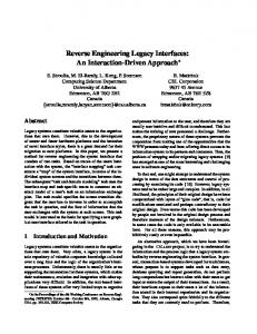
2.2 A reverse engineering environment design space HSU is a process of inverse domain mapping. For example, in the program understanding domain, programmers make use of programming knowledge, domain knowledge, and comprehension strategies when attempting to understand a program. They extract syntactic knowledge from the source code, and rely on programming knowledge to form semantic abstractions. Brooks' work on the theory of domain bridging [Bro83] describes the programming process as one of constructing mappings from a problem domain to an implementation domain, possibly through multiple levels. Program understanding then involves reconstructing part or all of these mappings. This process is expectation driven, and proceeds by creation, con rmation, and re nement of hypotheses. It requires both intra-domain and inter-domain knowledge. A problem with this reverse mapping approach is that mapping from application to implementation is one-to-many, as there are many ways of implementing a concept. To aid HSU, a reverse engineering environment must make this reverse mapping process easier by recovering lost information and making implicit information explicit. To do so, the environment must be exible in three areas: (1) it must support di�erent cognitive models and understanding processes; (2) it must provide an extensible toolset; and (3) it must be applicable to multiple domains. As illustrated in Figure 2.1, these three requirements form a design space [Lan90] for reverse engineering environment issues. Each of these areas is discussed in more detail below.
CHAPTER 2. PROGRAMMABLE REVERSE ENGINEERING
18
Manual
Automation level
Automatic Task specfic
Applicability
Monolithic
End-user programmable
Extensibility
General purpose
Figure 2.1: Reverse engineering environment design space
2.2.1 Cognitive models and the understanding process It is hard for any application designer to predict all the ways in which the application will be used. For a reverse engineering environment to support HSU, the main goal is to facilitate overall system comprehension. Since people learn in di�erent ways (for example, goal-directed (top-down and inductive) versus scavenging (bottom-up and deductive)), the environment should be exible enough to support di�erent types of comprehension. Two common approaches to system comprehension often cited in the literature are a functional approach that emphasizes cognition by what the system does, and a behavioral approach that emphasizes how the system works. For example, in the program understanding domain, both top-down and bottom-up comprehension models have been used in an attempt to de ne how a software engineer understands a program. However, case studies have shown that, in industry, maintainers of large-scale programs frequently switch between several comprehension strategies [vMV92]. Thus, the environment must support the diverse cognitive processes of HSU rather than impose a process that is not justi ed by a cognitive model other than that of the environment's developers. While creating the semantic abstractions during the system comprehension process, it
CHAPTER 2. PROGRAMMABLE REVERSE ENGINEERING
19
should be possible to include human input and expertise in the decision making. There is a tradeo� between what can be automated and what should or must be left to humans; the best solution lies in a combination of the two. Hence, the construction of abstract representations manually, semi-automatically, or automatically (where applicable), should be possible. Through user-control, the comprehension process can be based on diverse criteria such as business policies, tax laws, or other semantic information not directly accessible from the gathered data.
2.2.2 Toolset extensibility Most existing reverse engineering systems provide the user with a xed set of capabilities. While this set might be considered large by the system's producers, there will always be users who want something else. One cannot predict which aspects of a system are important for all users, and how these aspects should be documented, represented, and presented to the user. This is an example of the trade-o� between open and closed systems. An open system provides a few composable operations and mechanisms for user-de ned extensions. A closed system provides a \large" set of built-in facilities, but no way of extending the set. Instead of a closed architecture, a successful reverse engineering environment should provide a mechanism through which users can extend the system's functionality. There are two basic approaches to constructing extensible integrated applications from a set of tools: tool integration and tool composition [AHF93]. In tool integration, each tool must be aware of the larger environment, and the inter-tool interactions are coded in the tools themselves. This works for tightly-integrated environments, but in a loosely-coupled environment it is very di�cult to achieve. In tool composition, tool interaction logic resides outside of the tools. Each tool presents a standard, well-known interface to the outside world, and knows nothing about its environment; the environment contains all the inter-tool coordination logic. From an end-user perspective, the reverse engineering environment should manage tool composition, to facilitate the introduction of new tools into the system. This would allow
CHAPTER 2. PROGRAMMABLE REVERSE ENGINEERING
20
the user to provide their own tools for basic reverse engineering operations. These operations may be broken down into dealing with three types of HSU \artifacts:"1 (1) data, which is the factual information used as a basis for reasoning, discussion, or calculation; (2) knowledge, which is the sum of what is known and represents the body of truth, information, and principles acquired; and (3) information, the communication or reception of knowledge obtained from investigation, study, or instruction. Based on these de nitions, we can identify three canonical reverse engineering operation categories: (1) data gathering; (2) knowledge organization; and (3) information navigation, analysis, and presentation. These three operations are discussed below.
2.2.2.1 Data gathering Gathering data from the subject system is an essential step in reverse engineering. The raw data is used to identify a system's artifacts and relationships. Without it, higher-level abstractions cannot be constructed. Users should be able to indicate what artifacts they want gathered from the subject system, how (and when) they want this data gathered, and how they wish to represent it. This suggests the environment must facilitate the integration of data from sources other than the subject system, and that it should support incrementality as well. For example, the traditional approach to data gathering in a reverse engineering system for program understanding is to parse the subject system's source code and extract complete abstract syntax trees with a large number of ne-grained syntactic objects and dependencies. To accomplish this, many researchers have spent an inordinate amount of time building parsers for various programming languages and dialects [Cah92]. However, there already exists mature technology in the compiler arena to parse source code, perform syntactical analysis, and produce cross-reference and other information usable by other tools, such as debuggers. Thus, a reverse engineering environment should make use of this information whenever possible, and avoid \reinventing the wheel." 1
The de nitions used here are in accordance with Webster's online dictionary.
CHAPTER 2. PROGRAMMABLE REVERSE ENGINEERING
21
The user should be able to highlight important artifacts and relations in the data, and de-emphasize or lter out immaterial ones. This functionality is not just important from an aesthetic point of view; it is also a matter of scalability. For very large systems, the information generated during reverse engineering is prodigious. Simply presenting the user with reams of data is insu�cient; knowledge is gained only through the understanding of the data. In a sense, a key to HSU is deciding what information is material and what is immaterial: knowing what to look for|and what to ignore [Sha89].
2.2.2.2 Knowledge organization For HSU, gathered data must be put into a representation that facilitates e�cient storage and retrieval, permits analysis of the artifacts and relationships, and yet re ects the users' perspective of the subject system's structure. This requirement|the need to organize data in some well-de ned and rigorous manner|led to the development of data models [Bor80]. A data model captures the static and dynamic properties of an application needed to support the desired data-related processes. An application can be characterized by static properties (such as objects, attributes, and relationships among objects), dynamic properties (such as operations on objects, operation properties, and relationships among operations), and integrity constraints over objects and operations. The result of data modeling is a representation that has two components: (1) static properties that are de ned in a schema; and (2) dynamic properties that are de ned as speci cations for transactions, queries, and reports. A schema consists of a de nition of all application object types, including their attributes, relationships, and static constraints. Corresponding to the schema is a data repository called a database, an instance of the schema. A data model provides a formal basis for tools and techniques used to support data modeling. The three best-known classical data models are the hierarchical data model, the network data model, and the relational data model [Ull80]. The hierarchical data model is a direct extension of a primitive le-based data model; data is organized into simple tree structures. The network model is a superset of the hierarchical model; the objects need not be tree-
CHAPTER 2. PROGRAMMABLE REVERSE ENGINEERING
22
structured. The relational model is quite di�erent from the hierarchical or network model; it is based on the mathematical concept of a relation (a set of n-tuples), and organizes data as a collection of tables. All three classical data models are instances of the record-based logical data model [KS86]. Although well-suited to a computer environment, record-oriented data models are often semantically inadequate for modeling the application environment. They are highly machine-oriented and organized for e�ciency of storage and retrieval operations; ease of use for the non-programmer is of secondary importance. Typically, only two levels of abstraction are provided: the database schema, and the actual collection of records. There are no provisions to extend the levels to a more general hierarchy of types, meta-types, and instances, even though this extension would increase the model's expressive power and provide a mechanism which supports the reuse of common properties. The hierarchical and network models also do not support semantic relativism, which is the ability when modeling a system to view the elements and concepts representing it from di�erent perspectives depending on the application. In particular, the concepts of entity, relationship, and attribute should be interchangeable. For these reasons, the classical data models are also known as syntactic data models. The lack of abstraction mechanisms provided by the classical data models is particularly troublesome from an HSU point of view. Abstraction is a fundamental conceptual tool used for organizing information. It plays a key role in managing one of the fundamental problems with large-scale systems: complexity [Bro87]. When modeling such systems, the number of objects and relations in the knowledge base can grow very large. A large knowledge base| like a large software system|needs organizational principles to be understandable. Without them, a knowledge base can be as unmanageable as a program written in a language that has no abstraction facilities. Abstraction is the selective emphasis on detail: speci c details are suppressed and those pertinent to the problem at hand are emphasized. Abstraction mechanisms serve as organization axes for structuring the knowledge base. They focus on high-level aspects of an
CHAPTER 2. PROGRAMMABLE REVERSE ENGINEERING
23
entity while concealing details. Three of the most common abstraction mechanisms used are classi cation, aggregation, and generalization [Sow88]:
Classi cation: A form of abstraction in which an object type is de ned as a set of in-
stances. Classi cation captures common characteristics shared by a collection of objects, resulting in a generic object which captures the essential similarity among its constituents. An instance-of relationship is established between an object type in the schema and its instance in the knowledge base.
Aggregation: A form of abstraction in which a relationship between objects is considered
as a higher-level aggregate object. When considering the aggregate, speci c details of the constituent objects are suppressed. A part-of relationship is established between the component objects and the aggregate object.
Generalization: A form of abstraction in which similar objects are related to a higher-level
generic object. The constituent objects are considered specializations of the generic object. An is-a relationship is established between the specialized objects and the generic object.
There have been two basic approaches to addressing some of the de ciencies in the classical data models to \capture more of the semantics of an application" [Cod79]. Attempts have been made to extend the classical models by building higher-level conceptual models on top of them, and new more powerful semantic data models have also been developed to capture database concepts at a more user-oriented level. Semantic data models, starting with Abrial's semantic model [Abr74] and Chen's entity-relationship model [Che76], combined simple knowledge representation techniques, often borrowed from semantic networks [Fin79], with database technology. Semantic data models represent a shift in database research away from the traditional record-oriented model towards models which support more human-oriented semantic constructs. This shift is very similar to the goals in programming language research focusing on abstraction mechanisms for software development, and arti cial intelligence research into knowledge representation based on network representation
CHAPTER 2. PROGRAMMABLE REVERSE ENGINEERING
24
schemes [Gil90]. Conceptual modeling [BMS84] was introduced as a term re ecting this broader perspective. Conceptual modeling is the activity of formally describing aspects of some information space for the purpose of understanding and communication. Such descriptions are often referred to as conceptual schemata. A conceptual model and a conceptual schema are analogous to a data model and a database schema, respectively. One can think of data models as special conceptual models where the intended subject matter consists of data structures and associated operations. Classical data models, grounded on mathematical and computer science concepts such as relations and records, o�er little to aid database designers and users in interpreting the contents of a database. Semantic data modeling shares purposes with conceptual modeling. However, semantic data modeling introduces assumptions about the way conceptual schemata will be realized on a physical machine (the \data modeling" dimension). Thus, semantic data modeling can be seen as a more constrained activity than conceptual modeling, leading to simpler notations, but also ones that are closer to the implementation. The fundamental characteristic of conceptual modeling is that is it closer to the human conceptualization of a problem domain than to a computer representation of the problem domain [K�94]. The emphasis is on knowledge organization (modeling entities and their semantic relationships) rather than on data organization. The descriptions that arise from conceptual modeling activities are intended to be used by humans|not machines. Concepts in a conceptual model are indexed by their semantic content. This di�ers from other data models, such as relational, where the indexing scheme is more geared towards optimal storage and information retrieval from the implementation perspective. This is one of the main reasons that conceptual modeling is eminently suited to HSU: the focus on the end user is paramount.
CHAPTER 2. PROGRAMMABLE REVERSE ENGINEERING
25
2.2.2.3 Information navigation, analysis, and presentation Information processing represents the most important of the three canonical reverse engineering activities. While data gathering is required to begin the reverse engineering process, and knowledge organization is needed to structure the data into a conceptual model of the application domain, without the nal step of information navigation, analysis, and presentation, there would be no bene t to HSU. The user navigates through the hyperspace that represents the information related to their application, analyzes this information with respect to domain-speci c evaluation criteria, and uses various presentation mechanisms to clarify the resultant information. Many complex systems are not linear, but consist of many interwoven aspects better described using a multi-dimensional web of information artifacts [Mau92]. Unfortunately, as the size of this information space grows, the well-known \lost in hyperspace" syndrome may limit navigational e�ciency [MS88]. Moreover, it is di�cult to convey and communicate the wealth of information generated as a result of reverse engineering. This problem is exacerbated by the necessary coexistence of spatial and visual data. Theories of cognition suggest that imagery involves both descriptive and depictive information [Kos80]. For HSU, both spatial and visual information seem to play key roles in forming mental models of structure. The spatial component constitutes information about the relative positions of the artifacts in a neighborhood. It provides low-level, detailed information concerning the immediate neighborhood of the artifact in a graphical representation that facilitates the systematic exploration of the hyperstructure. The visual component preserves information about how a neighborhood (or a set of neighborhoods) looks (e.g., size, shape, or density). It provides a high-level view of the neighborhood; the essence of the entire image. Visual graph representations (i.e., rendering of nodes and arcs in various formats in a workstation window) aim to exploit the ability of the human visual system to recognize and appreciate patterns and motifs (e.g., central, fringe, or isolated components). Disorientation has been attributed to the tangle of links in the web [Nie90a]. The proliferation of links is often due to the weak link discipline enforced by a system using a
CHAPTER 2. PROGRAMMABLE REVERSE ENGINEERING
26
simple node/link mechanism, allowing unrestricted linking among arbitrary objects [NN91]. Such linking is very powerful, but potentially disorienting [BHLT93]. The same freedom which provides hypertext's exible structure and browsing capabilities may also be the direct cause of one of its greatest problems [BS91]. For users, disorientation may occur when browsing. For authors, the lack of design principles when creating associative links does not foster the creation of a consistent conceptual model [HKW91]. Some of the solutions that have been proposed to the classical problem of user disorientation within a large information space include: maps, multiple windows, history lists, and tour/path mechanisms [Nie90b]. Unfortunately, these methods do not scale up well. A more successful approach is through the use of composite nodes; they reduce web complexity and simplify its structure by clustering nodes together to form more abstract, aggregate objects [CTL+ 91]. Composite nodes deal with sets of nodes as unique entities, separate from their components. To aid information retrieval for navigation it should be possible to augment the search and selection operations built into the reverse engineering environment with user-de ned algorithms, and to interface with external tools as required. For example, in the program understanding domain, change requests are often couched in terms of the end-user's view of the application. Much of the e�ort involved in software maintenance is in locating the relevant code fragments that implement the concepts in the application domain. One should be able to use external tools that provide advanced searching techniques and have the results of their searches made available to the user and the environment. Analyzing the hyperstructure of the web can provide useful information. Various metrics and measures can be used to guide the creation of new artifacts in the information space, such as virtual nodes representing concepts not explicitly represented in the gathered data. The environment should support the integration of external analysis packages that implement domain-speci c metrics. The goal of environmental customizability includes modi cation of the system's interface components such as buttons, dialogs, menus, scrollbars, and of the integration of external
CHAPTER 2. PROGRAMMABLE REVERSE ENGINEERING
27
tools that present the information in di�erent ways. Since the user interface is a crucial part of the infrastructure of many software environments [YTT88], and since personal preferences for things such as menu structure, mouse action, and system functionality di�er so much from person to person (and from domain to domain), it is unlikely that any single choice made by the tool builder will suit all users. Presentation integration can occur at di�erent levels, including the window system, the window manager, the toolkit used to build applications, and the toolkit's look and feel [Was89]. The standardization provided by presentation integration lessens the \cognitive surprise" experienced by users when switching between tools. However, what is really needed is a way for the user to specify the common look and feel of the applications of interest to them, or of tools that are part of an application [Kle88]. In other words, users need to be able to impose their own personal taste on the common look and feel. This re nement of presentation integration moves the onus|and the opportunity|for reducing cognitive overhead due to the user interface from the tool builder to the tool user. Similarly, the way information is presented cannot be xed by the environment. For example, in the program understanding domain most reverse engineering systems provide the user with a xed set of view mechanisms, such as reference graphs and module charts. While this set might be considered adequate by the system's producers, there will always be users who want something else. It should be possible to create multiple, perhaps orthogonal, hyperstructures and view them using a variety of mechanisms, such as using di�erent graph layouts provided by external toolkits (e.g., [Ros94]).
2.2.3 Domain applicability Because HSU involves many di�erent scenarios and target domains, it is wise to make the approach as exible as possible for use in many di�erent domains. One way of maximizing the usefulness of a reverse engineering environment is to make it domain-speci c. By doing so, one can provide users with a system tailored to a certain task and exploit any features that make performing this task easier. However, this approach limits the system's usefulness
CHAPTER 2. PROGRAMMABLE REVERSE ENGINEERING
28
to a particular domain. Using the same system on a di�erent task, even one that is similar, may well be impossible. An alternative to making the environment powerful by making it domain-speci c, is to make it domain-retargetable. One would like to make the approach as exible as possible|a subtle distinction from general. Software can be considered general if it can be used without change; it is exible if it can be easily adapted to be used in a variety of situations [Par79]. General solutions often su�er from poor performance or lack of features that limit their usefulness. Flexible solutions may be tailored by the user to fully exploit aspects of the problem that make its solution easier. In particular, the reverse engineering methodology and supporting environment should be extensible, tailorable, and con gurable. It is essential that any approach to reverse engineering be applicable to large systems. For example, e�ective approaches to program understanding must be applicable to huge, multi-million line software systems. Such scale and complexity necessitates fundamentally di�erent approaches than is used in other domains. For example, not all software artifacts need to be stored in the repository; it may be perfectly acceptable to ignore certain details for program understanding tasks. Coarser-grained artifacts can be extracted, partial systems can be incrementally investigated, and irrelevant parts can be ignored to obtain manageable repositories. Knowledge organization, search strategies, and human-computer interfaces that work on systems \in-the-small" often do not scale up. For very large systems, the information accumulated during program understanding is staggering. To gain useful knowledge, one must e�ectively summarize and abstract the information. To achieve high functionality, many systems are targeted toward a single application domain, such as COBOL banking programs. While such systems are useful in their particular area, they are not widely applicable in others. Many current software reverse engineering environments support only relatively small programs. Others support just one programming language (or a subset of it), usually because their parsing system, database, and support environment are tightly coupled. This approach limits the application domain to small, \pure" programs rarely found in practice. One must take a pragmatic point of view; if the
CHAPTER 2. PROGRAMMABLE REVERSE ENGINEERING
29
methodology does not work on real-world software systems, with all their \features," then it will not make an impact on existing systems.
2.3 End-user programming The traditional de nition of programming takes the programmer's perspective: an activity in which instructions are written in a language that is compiled or interpreted into the application. From a user's perspective, a better de nition is to de ne programming by its objectives: to create an application that serves some meaningful function for the user. This task-speci c approach attempts to capitalize on a user's strengths by exploiting their skills and interests [Nar93]. The goal is to provide the user with as much exibility as possible in customizing the environment to suit their needs. One way of providing this functionality is through end-user programming. This goal has lead to a veritable ood of end-user programmable applications, virtually all of which are task-speci c.
2.3.1 End-user programmable applications Such programmability has proven e�ective in numerous application domains, including Computer-Aided Design (CAD), custom database applications, and statistical analysis packages. The CAD system AutoCAD provides end-user programmability through its AutoLisp interface. Database systems such as dBASE may be programmed to extend built-in functionality. Number-crunching packages such as Mathematica [Wol91] o�er a wide range of mathematical, statistical, and combinatorial routines that users can build upon in their analysis programs.
2.3.1.1 Personal computer applications Perhaps the most widely used end-user programmable application available on personal computers is the spreadsheet. The entry of values, formulas, and dependencies in a spreadsheet is a form of programming well-suited to end-user exploitation. As feature-laden as
CHAPTER 2. PROGRAMMABLE REVERSE ENGINEERING
30
they are, spreadsheets such as Lotus 1-2-3 and Microsoft Excel also o�er macro languages for expressing more elaborate sequences of computation. Business application suites are also beginning to provide scripting languages as a kind of unifying coordination mechanism. For example, Microsoft uses Visual Basic for Applications [Big93] as a common extension language for its suite of o�ce applications, including Microsoft Word. Similarly, Lotus provides LotusScript, a cross-application scripting language for their product o�erings. Third-party applications permit the user to tailor the interface of di�erent products from di�erent vendors to conform to their own particular stylistic guidelines (e.g., [Sof94]).
2.3.1.2 Text editors Text editors are a classic example of the di�culties that application designers face because of diverse user tastes and preferences. The question of which text editor is best is often the topic of seemingly unending religious debate. Personal likes and dislikes mandate customizability in text editors, perhaps more so than any other application, due to their wide-spread use. Devotees of the vi editor that comes with UNIX [KM81] trumpet that it works well with other UNIX tools. Disciples of emacs [Sta81] have praised the capabilities of its builtin extension and customization facilities, provided through a variant of Lisp. Emacs was constructed through the composition of separate and independent functions. By providing access to the same language that was used to implement it, the user can customize the editor by adding new or replacing existing commands and previous extensions. Its extensibility has been proven: code browsers, mail readers, and news readers have been constructed on top of the base editor. Another extensible text editor is IBM's Xedit. It allows users to write REXX scripts to extend its functionality beyond simple text processing. The choice of REXX as the scripting language was guided by the fact that it is also the scripting language of choice on VM/CMS (cf. Section 2.3.2.3), the original host operating system for Xedit (it has since been ported to other platforms). Followers of more graphical user interfaces look to editors such as Alpha on
CHAPTER 2. PROGRAMMABLE REVERSE ENGINEERING
31
the Macintosh, or BRIEF (Basic Recon gurable Interactive Editing Facility) [BRI] for DOS and OS/2. Alpha incorporates an extension language based on Tcl. BRIEF's basic premise is programmability: users can customize the editor by changing keystroke assignments and modifying existing commands.
2.3.1.3 Operating systems Operating systems represent another application area that incorporates end-user programmability to facilitate ease of use. Most operating systems provide scripting languages that users can write command procedures in. Some also provide lower-level command languages that can be used to tailor the operating system itself. For example, IBM's MVS operating system is extremely customizable, but it requires a skilled system programmer working in System/370 assembler and JCL to exploit this capability [EV93]. If one judges success from the size of the potential user community, the batch facilities provided by the MS-DOS command processor COMMAND.COM is the most successful. For example, the le AUTOEXEC.BAT (the script le executed whenever MS-DOS is booted) is typically altered by end users to launch their favorite applications and to con gure the system's characteristics. In fact, one could say that every MS-DOS command is simply a single-command script. UNIX is an adaptable, extensible, and nonspecialized operating system that is very dependent on scripting languages. In fact, it provides several: command language interpreters (shells) such as sh and csh; pattern matching languages such as sed and awk; and system programming languages such as perl. UNIX provides a set of core programs for common tasks; more complex tools are added to the UNIX toolkit by combining and connecting existing tools in various combinations using the shell. The shell is an ordinary program, not a system program; it can be changed or replaced by other versions if the user so desires. In this way, UNIX is similar to emacs: core functionality may be extended or replaced by the end user as needed.
CHAPTER 2. PROGRAMMABLE REVERSE ENGINEERING
32
2.3.2 Scripting languages In the past, end-user programming tools were sometimes called \macros" and \scripts," but they may also be thought of as very high level languages used to coordinate and glue various applications together. End-user programming languages amplify the power of an environment by allowing users to write scripts to extend the tool's facilities and to create a more e�cient and customized environment. In e�ect, the creation of an \application suite" can be accomplished by the end-user rather than the tool vendor(s). Unfortunately, scripting languages can be as hard to use as conventional programming languages. They may also be limited in three important ways: (1) there are too many of them; (2) they are normally bound to a speci c application; and (3) they don't always have the power and
exibility of traditional programming languages.
2.3.2.1 Tcl/Tk Tcl (Tool Command Language) is a good example of an application-independent embedded \universal scripting language." It provides an extendable core language, and was speci cally written as a command language for interactive windowing applications. It also provides a convenient framework for control integration among Tcl-based tools. Each application extends the Tcl core by implementing new commands that are indistinguishable from builtin commands, but are speci c to the application. Tk is an X11 toolkit companion to Tcl that implements the Motif look-and-feel. It is similar in functionality to the Xm toolkit, except the widgets may be programmed in Tcl rather than C.
2.3.2.2 HyperTalk and AppleScript HyperTalk [Goo90] is the scripting language used to program HyperCard [Hyp89], an application-independent hypertext system for the Apple Macintosh computer. A HyperCard script is a sequence of English-like HyperTalk statements that de ne a HyperCard stack. The HyperTalk language allows end users to access and control certain aspects of
CHAPTER 2. PROGRAMMABLE REVERSE ENGINEERING
33
the Macintosh environment without having to delve into the complexities of the Mac Toolbox. AppleScript is a newer and more general scripting language that allows end-users and other applications to control applications that are AppleScript-aware.
2.3.2.3 Rexx Rexx [Cow90] is a structured high-level language that was consciously designed to be easy to read and write. Although rst made commercially available by IBM for their VM/CMS operating system in 1983 as a system-procedure language, and a replacement for the older EXEC-2 language, Rexx has since been ported to MVS, UNIX, DOS, OS/2, and the Commodore Amiga. Rexx is application-independent and thus can act as a single scripting language by all Rexx-aware applications that use the required interface. For example, on VM/CMS the text editor Xedit may be programmed in Rexx; Amiga's under AmigaDOS use ARexx as the primary scripting and integration mechanism; PC's under OS/2 use Rexx in a similar manner.
2.3.3 Summary Existing systems that o�er end users the capability to extend and customize their applications typically do so through a task-speci c programming language. While extensible to varying degrees, text editors such as vi, emacs, and BRIEF su�er from sometimes cryptic command sequences and the need for the user to learn yet another programming language. Even worse, the language they must learn is di�erent for each application. Editors such as Alpha and Xedit rectify this problem somewhat by using embedded scripting languages that are used in other applications. Some vendors are also taking this approach of using common cross-platform and cross-application extension languages.
CHAPTER 2. PROGRAMMABLE REVERSE ENGINEERING
34
2.4 Domain-retargetable reverse engineering It has been repeatedly shown that no matter how much designers and programmers try to anticipate and provide for users' needs, the e�ort will always fall short. This is not the fault of the designers and programmers; in general, it is impossible to know in advance all that will be needed. No one can foresee all the situations their systems and applications will encounter; customizations, extensions, and new applications inevitably become necessary. This lack of exibility forces users to spend much of their time transferring their domain knowledge to the application programmer. A better approach would be to allow the users to exploit the domain knowledge themselves. Hence, the goal is to provide the user with as much exibility as possible in customizing the environment to suit their needs. The three areas that a reverse engineering environment must be exible in to support HSU (cognitive models, toolset extensibility, and domain applicability) can be addressed by providing the end user with the capability to program the environment. Given that end-user programming has shown promise in other application domains, it seems natural to apply a similar approach to HSU, particularly since the canonical activities for reverse engineering to support HSU, as described in Section 2.2.2, lend themselves to customization. By incorporating end-user programming into these key activities, the de ciencies that exist with other approaches can be alleviated. We advocate a new approach to reverse engineering that re nes the traditional twostep approach of information extraction and abstraction as outlined in [Arn90]. The new three-step approach is as follows: 1. Model: Construct domain-speci c models of the application using conceptual modeling techniques. 2. Extract: Gather the raw data from the subject system using the appropriate extraction mechanisms. 3. Abstract: Create abstractions that facilitate HSU and permit the navigation, analysis, and user-de ned presentation of the resultant information structures.
CHAPTER 2. PROGRAMMABLE REVERSE ENGINEERING
35
The new approach achieves domain-retargetability through end-user programming. The environment becomes user-oriented, not builder-oriented, since it allows the user to model the application domain, to leverage their cognitive powers and domain knowledge, and to extend the reverse engineering environment's toolset functionality and interface. Hence, the environment's applicability, modeling capabilities, and analysis techniques are no longer limited by its original designers. The approach also permits a smooth transition to automatic reverse engineering where appropriate.
2.5 Summary This chapter described a new domain-retargetable approach to HSU that integrates conceptual modeling, reverse engineering, and end-user programming. Key issues in the design of a reverse engineering environment were discussed, and three canonical reverse engineering activities were identi ed. A new interpretation of the term \programming," the success of end-user programming in various application domains, and the use of various scripting languages to extend program functionality were presented. The next chapter describes the architecture for a meta reverse engineering environment that supports the new approach.
Chapter 3
The PHSE \One of the problems with standards is that they must be general enough to appeal to many di�erent users. How then to customize them for personal taste? In the best of both worlds you'd be able to customize standard tools to best t your needs." | Jane M. Tazelaar [Taz90].
3.1 Introduction This chapter describes the programmable hyperstructure editor, a meta reverse engineering environment framework. It supports the approach to domain-retargetable reverse engineering outlined in Chapter 2. The PHSE architecture, model, and prototype implementation are presented. The architecture of the PHSE supports the canonical reverse engineering operations outlined in Section 2.2.2. It provides a programmable interface to its core functionality, to its conceptual model, and to its user interface. The integration facilities provided by the architecture are outlined. The PHSE model provides the domain-independent conceptual schema that user's specialize for their application. Supporting the conceptual model is a data model based on 36
CHAPTER 3. THE PHSE
37
semantic networks. The rationale for the choice of the conceptual modeling language and the implications on the use of a semantic network data model on the PHSE implementation are discussed. A prototype implementation of the PHSE is presented. Based on an existing environment for reverse engineering, it faithfully supports the approach to reverse engineering espoused in this research, implements a signi cant portion of the PHSE architecture, and supports the model. The hypertextual interface for navigating the information space is described.
3.2 Architecture Data gathering, knowledge organizing, and information navigation, analysis, and presentation were identi ed in Section 2.2.2 as canonical operations of the reverse engineering process. To support end-user programmability of these operations, a core set of functional components must be made available to both the user and other tools. These core components must provide functionality upon which a more powerful and domain-speci c toolset may be constructed. This section outlines the architecture of a meta reverse engineering environment that meets these objectives. As illustrated in Figure 3.1, the service architecture of the PHSE is ring-based. Its components directly address each of the basic reverse engineering operations stated above. At the center of the architecture is the kernel, which is a script language interpreter. Just outside the kernel, the core provides a minimal set of reverse engineering functionalities. Beyond the core is the human and tool interface ring which provides presentation services and access to external tools. The outer personality ring consists of domain-dependent scripts and other HSU extensions. Beyond this outer ring the user can provide additional rings that further extend the capabilities of the environment.
CHAPTER 3. THE PHSE
38
Data Gathering
Knowledge Organization Kernel
Information Navigation
Presentation
Analysis Human / Tool Interfaces Domain-Specific Personality
Figure 3.1: The PHSE's ring architecture
3.2.1 The kernel The kernel is the centerpiece of the system that serves as a router to coordinate control integration within the PHSE. It provides a consistent and system-wide basis for building scriptable functionality. Although the architecture does not mandate the choice of any particular embedded scripting language, it should address some of the de ciencies outlined in Section 2.3.2. For example, it should be in fairly common use in other applications, it should be \easily" programmable by non-experts (if possible), and it should permit the integration of applications written in other implementation languages.
3.2.2 The core The core ring implements the canonical reverse engineering operations described above. The data gathering component provides support for extracting artifacts from the subject system and loading them into a knowledge base. The knowledge organization component provides
CHAPTER 3. THE PHSE
39
the user with conceptual modeling machinery for creating models of the application domain. The information navigation, analysis, and presentation component provides the user with tools for browsing and editing the hyperstructure representation of the subject system, for analyzing selected aspects in the knowledge base, and for presenting information created through the aforementioned analysis. The core components1 are registered with the kernel and available to the user and external applications through the interface ring. Extensions to the core make use of these capabilities to compose more powerful tools. These extensions are also registered with the kernel and from then on treated the same as a core command. In this way, the core operations can be enhanced, or even supplanted.
3.2.3 The interface ring The interface ring provides access to the services provided by the PHSE. It separates user interface concerns from the computational concerns of the core and kernel, providing interfaces to the core components for both users and tools. The human interface supports customization of the user interface, while the tool interface provides an application program interface by which external tools can access the functionality of the core and the extended functionality registered with the kernel.
3.2.4 The personality ring Domain-retargetability is the capability of molding and adapting the PHSE to di�erent domains. It is achieved through the personality ring, which provides domain-speci c tools and interfaces to its clients. In the personality ring, a user can extend the built-in core operations with both domain-independent and domain-dependent algorithms. Domainindependent extensions may re ect personal choice of such things as the user interface, while domain-speci c extensions may incorporate new algorithms that augment the core. For example, in the program understanding domain, the user may integrate external tools 1
The toolset provided with the prototype implementation is described in Section 3.4.3.
CHAPTER 3. THE PHSE
40
for graph layout, complexity measures, pattern matching, slicing, clustering, and so on (or they may choose to write these algorithms themselves in scripts).
3.2.5 Summary The architecture of the PHSE directly addresses the main services previously identi ed as required by a reverse engineering system. The structure is strati ed into rings, with a script language kernel at the center. The core provides the backbone upon which extensions can be built. The interface ring supports user interface customizability and access to editor functionality by external tools. The personality ring supports domain-retargetability. The PHSE architecture represents a meta reverse engineering environment. An instantiation of the PHSE into a domain-speci c reverse engineering environment can be constructed by the end-user by adding domain-speci c tools to those supplied by the PHSE core and gluing them together with scripts.
3.3 Model The PHSE model is composed of two parts:2 a conceptual model and a data model. The conceptual model represents an organization of the artifacts and relations of complex hyperstructures. The PHSE model acquires its semantics when it is instantiated for a speci c application domain (cf. Chapter 4). The data model is the foundation upon which the conceptual model is constructed. It is best characterized as a special purpose semantic network.
3.3.1 Telos: A language for conceptual modeling Telos is a conceptual modeling language designed to capture various kinds of knowledge about information systems. It integrates concepts from knowledge representation, semantic The mechanism used for storing the data model in a physical knowledge base in the prototype implementation of the PHSE is described in Section 3.4.2. 2
CHAPTER 3. THE PHSE
41
networks, deductive and temporal databases, software engineering, and structurally objectoriented programming languages. This section gives a simpli ed overview of Telos. Two components of Telos not discussed here are the representation of temporal knowledge and the representation of assertional knowledge. For a more detailed description of Telos, see [KMSB89, MBJK90, Myl91].
3.3.1.1 The representational framework The representational framework of Telos generalizes graph-theoretic data structures used in semantic networks, semantic data models such as the entity-relationship model, and objectoriented representations, by providing a single modeling unit, named proposition. Every Telos knowledge base is a collection of propositions, which can be divided into two disjoint kinds: individuals (sometimes called an entity, concept, or node in other formalisms), and attributes (sometimes called a relationship or link). An individual may represent a concrete real-world entity such as Eric Cantona or an abstract entity such as Football Team. An attribute represents a binary relation between pairs of propositions. Formally, propositions are 3-tuples3 with components from, label, and to denoting the source, label, and destination propositions; these components are themselves propositions. For example, Attendance is represented as Attendance =
Thus, Attendance is the name of the proposition de ned by the 3-tuple. Similarly, individuals are represented as 3-tuples. For example, Football Team is represented as Football Team :=
Individuals are self-referential. Labels of individuals are not signi cant. Since components of a proposition that are not of interest to us are denoted by the ellipsis (...), the label of the Football Team proposition is therefore represented by ... . Telos propositions are in fact 4-tuples, with when as the fourth component, denoting the duration of the proposition. Temporal knowledge is not part of the current PHSE model. 3
CHAPTER 3. THE PHSE
42
A collection of attributes that have a common source proposition is a structured object. For example, a structured object with the common source Football Team can be represented by the following attributes: Attendance := Players := Coach := Home Field :=
These attributes de ne the individual Football Team to consist of the attributes Attendance, Players, Coach, and Home Field. This is a form of implicit aggregation. Hence, we do not have to use an explicit aggregation construct that connects attributes to the source proposition. In addition to structuring objects through aggregation, Telos supports two other important structuring mechanisms: classi cation (and its inverse instantiation) and generalization (and its inverse specialization).
3.3.1.2 The classi cation dimension Classi cation relates a class of propositions with speci c instances of the class. A class determines the kinds of attributes and the properties of the instances. For example, since Manchester United is an instance of Football Team, it will have attributes Attendance, Players, Coach, and Home Field, and the following de nition of Manchester United conforms to these attributes:
CHAPTER 3. THE PHSE
43
An important classi cation constraint that is satis ed by this de nition of Manchester United is that the attributes of Manchester United are instances of the attributes of Football Team. For example,
*
instance-of
*
Classi cation is based on an in nite proposition dimension that can be classi ed into tokens (propositions having no instances, such as Manchester United), simple classes (propositions having only tokens as instances, such as Football Team), and meta classes (propositions having only simple classes as instances), and so on. The Telos framework accommodates an in nite number of such classi cation levels, with each level containing instances of classes in the subsequent level, forming instance-of instantiation hierarchies. For example, meta meta classes have meta classes as instances. The only exceptions to this rule are ! classes, which have objects at any levels as instances. ! classes are used to provide a framework for modeling the commonality between all the instantiation levels. For example, the ! class Proposition provides a formal way of tying together all the propositions in a Telos knowledge base, since all propositions are instances of the ! class Proposition (including itself). Knowledge engineers who are building conceptual models of the real world will not typically de ne additional ! classes. In fact, most real-world modeling takes place at the token and simple class levels. In addition to the ! classes, Telos comes with the following pre-de ned classes: Token, a simple class that has all tokens as instances; SimpleClass, a meta class that has all simple classes as instances; and MetaClass, a meta meta class that has all meta classes as instances. This list goes on for all required classi cation levels.
CHAPTER 3. THE PHSE
44
3.3.1.3 The generalization dimension Orthogonal to the classi cation dimension, classes can be specialized through generalization, forming is-a specialization hierarchies (with the exception of the token level). For example, Football Team is a specialization of the class Team:
*
is-a
*
Only classes residing on the same classi cation level can be is-a related. Non-token attributes of a class are inherited by its specializations. Telos supports multiple inheritance, permitting a class that is a specialization of more than one class to inherit the attributes of all its generalizations.4 Attributes that are inherited by a class can be specialized to re ect the semantics of the specialized class more accurately.
3.3.1.4 The attribute mechanism As shown above, every proposition can have attributes associated with it. One of the novel features of Telos is that attributes are also represented by propositions; therefore, they can be instantiated, specialized, and have attributes of their own. This, together with its assertion language, provides the basis for Telos' extensibility. In terms of proposition representation, the existence of an attribute class enables the creation of attribute tokens for the instances of its source component. For example, the builtin class Attribute := 4
A special Telos clause may be used to get around the problem of ambiguous attribute inheritance.
CHAPTER 3. THE PHSE
45
enables us to create an attribute of an instance of a Proposition with the attribute category attribute. This in turn enables the creation of attribute categories for the subclass.
3.3.1.5 Rationale Telos was selected over other modeling languages because it is more expressive with respect to attributes, it is extensible through its treatment of metaclasses, and it has already proven successful in other application domains. For example, it has been used to provide a structural framework for an authoring-in-the-large hypertext system [Sob91], and to perform requirements analysis in a software engineering environment DAIDA [JMSV91]. The primitive units of Telos, individuals and attributes, have a direct mapping to the primitive units of hypertext, namely nodes and links. Furthermore, attributes are treated as \ rst class citizens" when it comes to the built-in domain-independent structuring mechanisms for aggregating, classifying, and generalizing artifacts. This results in a uniform framework and provides solutions to the knowledge organization issues discussed in Section 2.2.2.2. Telos' meta-modeling facilities for describing structures unique to a domain means that it can represent a wide variety of conceptual models. Although not used in the current realization of the PHSE, its assertion language, integrity constraint mechanism, and deductive rules for re ning the structural knowledge of Telos, and its facilities for representing and reasoning about temporal knowledge, also provide additional bene ts.
3.3.2 Conceptual model The PHSE conceptual model is the basis upon which users construct domain-speci c models. As illustrated in Figure 3.2, it is relatively minimal, due in part to the fact that Telos is used in its speci cation. Telos provides most of the modeling and knowledge organization facilities required; only a few extra artifacts and attributes are needed. The central component in the PHSE conceptual model is the PHSEObject; everything is derived from it. It is a SimpleClass object, an instantiation of the PHSEObjectClass
CHAPTER 3. THE PHSE
46
SimpleClass MetaClass
PHSEObject
PHSEWeb attribute necessary single:id Integer attribute:annotation Proposition
PHSEObjectClass
Figure 3.2: The PHSE schema meta class, with two attributes: a unique identi er (the primary search key) and a set of annotations. No other constraint is placed on a PHSE object. The only other special component is the PHSEWeb, an unordered collection of PHSEObjects; its use is discussed in Sections 3.3.3 and 3.4.3.3. A complete listing of the Telos speci cation of the PHSE conceptual model is given in Appendix B.
3.3.3 Data model The PHSE data model, upon which the conceptual model is built, is a general-purpose semantic network, represented as an attributed graph. Attributed graphs are well suited to represent structured sets of data artifacts [Roh87]. In its most basic form, a semantic network represents knowledge in terms of a collection of objects (representing concepts) and binary associations (representing binary relations over these concepts). According to this view, a knowledge base is a collection of objects and relations de ned over them [ML84]. The semantics of the model are a careful de nition of the meaning and usage of the nodes and arcs. In the PHSE data model, both artifacts (represented as nodes) and relations (represented as arcs) are specializations of the PHSEObject class. Modi cations to the knowledge base occur through the insertion or deletion of objects and the manipulation of relations. The use of a network data model has at least three advantages related to navigating, structuring, and visualizing the knowledge base. The rst advantage is that the network data structures that encode information may themselves serve as a guide for information retrieval [Hen79]. The association between artifacts de nes implicit access paths. The
CHAPTER 3. THE PHSE
47
fundamental assumption in the use of semantic networks is that all information about a given conceptual entity is reachable from a common place [SGC79]. The second advantage is the use of the organizational principles described in Section 2.2.2.2 to structure the knowledge base. The abstraction mechanisms classi cation, aggregation, and generalization capture the natural structure of the artifacts in the system, their properties, and the relationships among them [Alb89]. They can also be used recursively to construct abstraction hierarchies [PCW85, Was85]. Such taxonomic organization is an essential human activity that allows us to cope with multitudes of detail [BMW84]. The third advantage is that network representation schemes lend themselves to a graphical notation that can be used to depict knowledge bases and increase their understandability. The popularity of entity-relationship diagrams to model an enterprise is an excellent example. Most human beings visualize structure graphically. Designers often describe system architecture using block diagrams of the major system components and labels that refer to their major functions. Modern interactive systems with graphical display capabilities facilitate the direct manipulation, processing, and presentation of information in graphical form. The PHSE data model consists of four objects: webs, nodes, links, and attributes. A web is a subset of the entire knowledge base that is related is some fashion. It is composed of typed nodes representing artifacts and typed arcs representing relations. Each node has a set of incoming arcs and a set of outgoing arcs. A node represents an artifact in the target domain. Links between nodes represent relations between artifacts. Nodes and links may exist simultaneously in one or more webs. For example, in the program understanding domain, a node representing a C++ function may be part of a web of functions that call one another, part of a web of member functions for a class, and a web of overloaded functions. This permits object sharing and facilitates multiple views of the data. An example of several webs is shown in Figure 3.8. In the gure, the stippling of the arcs and nodes represents di�erent arc and node types, respectively. The singleton node in the selected set is part of (at least) three di�erent webs visible in the gure.
CHAPTER 3. THE PHSE
48
Object semantics are provided through user-de ned attribute/value pairs, which can be attached to nodes or links. Attribute/value pairs permit the organization of nodes and links into subgraphs and webs. For example, subsets of objects may be extracted from large graphs using ltering mechanisms based on attribute predicates.
3.4 Realization This section discusses the realization of the PHSE. The high-level application programming interface (API) is outlined. All core functions registered with the kernel are provided in a series of startup les that the editor loads upon invocation. The implementation of the PHSE prototype as an evolution of an existing environment for reverse engineering is described. By building on previous work, the prototype's functionality was greatly increased, and the time to develop the prototype was similarly decreased. Finally, the standard toolset provided by the PHSE is detailed. Operations for each canonical reverse engineering category of data gathering, knowledge organization, and information navigation, analysis, and presentation and provided by the PHSE; their implementation and use is illustrated. More real-world examples of the PHSE's use will be provided in the next chapter.
3.4.1 API The interface ring described in Section 3.2 provides access to the operations provided by the core of the PHSE. These operations may be categorized as atomic and composite. Both are domain-independent. The atomic operations are grouped into two major components: information model and user interface. Operations on the information model include create operations to create new objects, delete operations to destroy objects, get operations to retrieve data from artifacts, or to retrieve artifacts from the knowledge base, set operations to modify data associated with an existing artifact, and miscellaneous operations that do not t into any of these categories. Composite operations are built on top of the atomic operations. They make use of
CHAPTER 3. THE PHSE
49
object attributes in a domain-independent way that is suitable for HSU. The interpretation of object attributes is left to the client of the composite operations. Examples of composite operations include selecting artifacts based on some attribute (either the existence of the attribute or the attribute's value), ltering objects from the current neighborhood5 view (see below), and loading and saving a neighborhood to an external application. All domain-dependent operations are built on top of a combination of the atomic and composite operations provided by the core. Users may extend the functionality of the core in both a domain-independent and a domain-dependent manner. By extending the operations in a domain-independent manner, the user can provide more operations that, for example, display nodes using various layout algorithms that rely solely on graph-theoretic, and hence domain-independent, information. By extending the operations in a domain-dependent manner, the user tailors the PHSE to a particular task or set of tasks.
3.4.2 Implementation A prototype version of the PHSE was implemented by retro tting the PHSE architecture onto Rigi IV, the Rigi system discussed in Section 1.4.3, resulting in Rigi V. It consists of roughly 7,500 lines of RCL code that sits on top of the C++ code that comprises rigiedit. The evolution of Rigi IV into Rigi V was a three-step process. The rst step was to make rigiedit scriptable [TWMS93]. The second step was to make the user interface customizable [Til94]. The third step was to integrate a conceptual modeling capability into the editor. Selected implementation details on all three steps of this process are provided in Appendix A.
3.4.2.1 Core functionality RCL (R igi C ommand Language) is the scripting language used to form the extensible PHSE kernel. Rather than writing yet another command language, RCL is implemented on top of Tcl. As discussed in Section 2.3.2.1, Tcl provides an extendable core langauge, 5
Neighborhoods are described in Section 3.4.3.3.
CHAPTER 3. THE PHSE
50
and was speci cally written as a command language for interactive windowing applications. It also provides a convenient framework for communicating between Tcl-based tools. Each application extends the Tcl core by implementing new commands that are indistinguishable from built-in commands, but are speci c to the application. These new commands may be implemented in languages such as C, C++, or Scheme, or as interpreted Tcl scripts. Tcl is application-independent and provides two complementary interfaces: a textual interface to users who issue Tcl commands, and a procedural interface to the application in which it is embedded.
3.4.2.2 User interface Although the PHSE architecture does not mandate the choice of any particular scripting language in its implementation, Tcl seemed a good choice given the implementation environment6 and the existing user base of Tcl programmers. An added advantage of using Tcl as the basis for the scripting language is that it can be used in conjunction with the Tk toolkit to customize the environment's interface. All of the system's interface components can be con gured using RCL commands. This makes it possible for users to write Tcl programs to personalize the layout and appearance of the environment as desired. For example, users can rebind keystrokes, change mouse buttons, or replace an existing operation with a more complex one speci ed as a set of RCL commands. Moreover, since the scripting language is interpreted, the graphical user interface can be dynamically altered by using the appropriate RCL commands. Hardware consisting of Sun 4's and IBM RS/6000's, software consisting of UNIX, X windows, OSF/Motif. 6
CHAPTER 3. THE PHSE
51
3.4.2.3 Model A Telos implementation is not part of the Rigi V prototype.7 In its place, the PHSE model is implemented at the database physical level as a store of binary relations, similar to the mechanism used in [BDTTJ94]. The user speci es the domain model in a set of les using a simpli ed mechanism for describing the artifacts, entities, and attributes that constitute a knowledge base; details are provided in Section A.2.3. The binary relations that represent the knowledge base are stored in one or more les as a series of RSF (R igi S tandard F ormat) triples. Each triple is of the form type subject object. The interpretation of this relation is straightforward: a directed relation of the type `type' is asserted between the subject and the object. Using this simple binary mechanism, both intensional and extensional information are represented. Intensional information de nes the structure of the information (the schema of the knowledge base, interpreted as meta-data), while the extensional information comprises the actual occurrences of relationships (the instance of the knowledge base; interpreted as data) . In this way, an RSF representation of the knowledge base can be used to represent all Telos propositions, from meta classes to tokens, in a uniform manner. It also implies that a knowledge base can encode its own schema, bootstrapping itself by providing its own semantics, making it portable. For example, in the program understanding domain, the RSF triple call foo bar might indicate the existence of a call relationship between the function foo and the function bar. Likewise, the RSF triple in function foo could indicate that foo is an instance of the function class. The other structuring mechanisms provided by Telos can also be represented as RSF triples, for example, aggregation using member and specialization using isa. Since every n-ary relation can be expressed as a conjunction of n + 1 binary relations [Kow79], the RSF mechanism is su�cient to store the information required by the PHSE. A su�ciently robust implementation of Telos was unavailable at the time. However, the modeling capabilities of Telos are still used in the PHSE; they are just implemented in the Rigi V prototype in a di�erent manner. A full Telos implementation is integrated in a larger environment for program understanding, described in Section 5.4. 7
CHAPTER 3. THE PHSE
52
Figure 3.3: The PHSE toolset Its simplicity also permits the facile translation to and from other data formats (such as Prolog facts), the incorporation of retrieval improvement techniques (such as inverted lists or B-trees), and the use of dedicated tuple engines (such as qddb [HF94]) into the PHSE toolset.
3.4.3 Toolset The prototype implementation of the PHSE provides support for all key aspects of the architecture. It provides a variety of tools for loading, saving, and exchanging knowledge base artifacts with other tools. It permits dynamic domain switching. Perhaps the richest component of the prototype is the information editor: it facilitates the navigation, analysis, and presentation of information in the knowledge base in a multi-window graphically-oriented manner.
CHAPTER 3. THE PHSE
53
3.4.3.1 Data gathering The operations provided for data gathering permit the user to load and save a knowledge base in a variety of formats, to clear the knowledge base, and to update the knowledge base. The formats currently supported include GEF, GXF, RSF, Telos, and Tess. End users can extend this list as they see t. GEF is a format used in the GraphEd graph layout package [Him93]; it can be used to display webs in a variety of layouts (cf. Section 3.4.3.3). GXF [Eig93] is another graph exchange format used in several research groups, such as Hy+ [CMR92], MacroScope [KLO+ 93], and computational geometry [Lyo94]. RSF is the primary means of loading or saving a knowledge base. Telos S-expression format may also be used to load or save the knowledge base (or selected portions). Finally, Tess format is used to communicate with a computational geometry package (see below) [Won91]. Data is loaded or saved to and from the knowledge base, or from a speci c neighborhood, as directed. For example, the user may wish to save the entire knowledge base in Telos format, or save just a current neighborhood for exporting to an o�ine graph layout server. The clear operation empties and initializes a knowledge base, while the update operation causes the knowledge base to be updated to re ect the current neighborhood (see the discussion on web splicing in Section 3.4.3.3). Although RSF is currently the format most commonly used when loading and saving a knowledge base, there is no reason why end users could not use RCL or any other procedural interface. For example, existing RSF tuple streams could be processed by the RCL interpreter by simply sourcing the le (assuming the user had provided procedures for each relation). The rst element of the RSF tuple could be taken as a procedure name, say call, which takes two arguments, caller and callee. An RSF stream of call caller callee relations would then be interpreted as a series of invocations of the call procedure, which would in turn create the necessary nodes and arcs in the knowledge base by calling necessary PHSE core operations. This mechanism could be extended to non-RSF streams and di�erent paradigms, for example, object-oriented using [incr tcl] [McL94].
CHAPTER 3. THE PHSE
54
Figure 3.4: Displaying active RCL variables and procedures
3.4.3.2 Knowledge organization The operations supplied under the knowledge organization moniker include retargeting the PHSE to a new domain, interrogating the values of RCL variables and procedures active in the current environment, and viewing the current schema. Retargeting the PHSE to a new domain causes the current knowledge base to be cleared, a new one to be optionally loaded, and a new set of domain-speci c interface routines to be created (based on RCL routines provided by the user). Figure 3.4 illustrates the use of the RCL variable and procedure display widget. The user has listed all procedures that match the regular expression data save* and has chosen to view the body of the data save telos sexpr procedure. The editor used is point, a Tcl/Tk-enabled text editor [Cro94]. It has been augmented with an update operation that facilitates exploratory RCL coding when using the PHSE. The text being edited is a dynamically constructed version of the procedure's body.8 The update operation uses 8
Produced through Tcl's info command.
CHAPTER 3. THE PHSE
55
Figure 3.5: A neighborhood Tcl's send command to instruct the PHSE to \source" the temporary le. In this way, the functionality of an existing procedure can be changed on the y. The RCL editor operation also invokes the point editor on a user-speci ed le, enabling the users to create new RCL procedures in a similar manner. The schema browser can be used to view the conceptual model for the current domain, and instances of the schema (i.e., the active knowledge base) if desired. The browser is based on a prototype from the University of Toronto. An example of it in use is shown in Figure 3.2; further examples will be provided in Chapter 4.
3.4.3.3 Information navigation, analysis, presentation The information component of the PHSE is a graphical, hypertext-oriented, multi-window hyperstructure editor. As discussed in Section 3.3.3, hypertext is a suitable paradigm for visualizing and understanding the structure of large information spaces. Interrelated webs of objects form the cornerstone of the PHSE information paradigm.
CHAPTER 3. THE PHSE
56
Portions (or all) of a web are viewed by the user as a neighborhood. A neighborhood is simply a collection of artifacts that are immediately accessible from the current perspective. It is graphically represented in the PHSE by a single window containing the artifacts, as shown in Figure 3.5.9 Artifacts can exist in any number of neighborhoods simultaneously, since neighborhoods are simply dynamically computed perspectives of the underlying knowledge base. This permits multiple, co-existing views of the information space. To accelerate web traversal and aid information access and retrieval, strands may be used. Strands are nodes that act as \bookmarks" or quick entry points into a web. Each node in the knowledge base has a binary `strand' attribute. If set, the node also exists in a special neighborhood of strands. They can be reached and edited by using the strand editor: a window that simply displays all current strands. One can think of strands as pieces of a web that dangle outside its normal boundary, that one can get a \handle" on.
Navigation
Information navigation involves three subcomponents: selection, editing, and traversal. Artifacts are selected by the user according to various criteria, including visual and spatial cues, attributes, and structural properties. A node may be selected by a single mouse click (default action), or by rubber-banding around a set of nodes in a neighborhood. In addition to the simple selection routines for selecting all nodes in the current neighborhood, deselecting all nodes in the current neighborhood, and inverting the current selection, widgets are also provided for attribute-based and structure-based selection. These widgets are shown in Figure 3.6; the menus for attribute, node type, arc type and direction, and comparison are torn o� to show the possible choices available to the user (the choices shown as menu items are constructed automatically from the domain model speci cation). Attribute-based selection permits the user to identify artifacts that have particular attributes of speci ed values. Structure-based selection permits the user to identify artifacts that meet speci ed structural criteria (for example, all nodes with two or more incoming This gure actually contains more than a simple neighborhood display; see the discussion on information presentation below. 9
CHAPTER 3. THE PHSE
57
Figure 3.6: Attribute- and structure-based selection widgets call arcs). For both methods, there are options to search beyond the current neighborhood into the rest of the knowledge base (Search KB), and to non-destructively add to the current selection set (Keep). Other, more advanced and/or domain-speci c selection techniques can be added by the user. For example, in the program understanding domain, the SCRUPLE pattern matching engine [Pau92] may be invoked to identify artifacts with certain syntactical patterns in their associated source code les.
Editing the web involves creating new artifacts, deleting existing ones, or changing an artifact's attributes. The attributes of individual artifacts may be altered using the attribute editor widget (not shown). New arcs may be created graphically by drawing a line between two nodes in a neighborhood window. New nodes may be created using the web edit widget. It provides several mechanisms for altering webs, for creating new strands, and for changing the structure of the knowledge base itself. The web edit widget is shown in Figure 3.7. Operations take place either in the current neighborhood or to and from the clipboard. Operations in the current neighborhood involve either the creation of a single node, or the deletion of the set of selected nodes. In the simplest case, a new node is temporarily inserted into the current neighborhood. The node's name and type may be set by the user;
CHAPTER 3. THE PHSE
58
Figure 3.7: Web edit widget by default they take the values new and the current nodetype value. If the strand option is speci ed, then the new node is also made a strand. If the splice option is speci ed, then for each arctype in the current inarcset,10 a new arc is created from each parent of the current neighborhood to the new node. If a node set is being deleted, then there are two options. If splicing is not speci ed, then each node in the currently selected set, and each arc either incoming or outgoing of each node, is deleted from the knowledge base. If splicing is speci ed, then each member of the selected set is detached from each parent of the neighborhood by deleting all arcs of the types speci ed in the inarcset between each parent and each member. Each parent is then connected to each child of each node in the selected set (children are the nodes connected by outgoing arcs of the current outarcset of the currently selected node) by each arc in the current inarcset. A check is then made to see if each member of the selected set was a member of any other web using the current inarcset; if not, then each outgoing arc of the type speci ed in the outarcset is deleted. This check is necessary to ensure that children of the currently selected set are still accessible from other webs after the deletion if they were accessible before. After this check, if there are no incoming arcs of any type for each The PHSE maintains two active sets of arcs. The inarcset is the set of incoming arc types, and the outarcset is the set of outgoing arc types. 10
CHAPTER 3. THE PHSE
59
==>
Legend: in arcset:
previous neighborhood:
out arcset:
current neighborhood:
selected set:
parents:
Figure 3.8: Web splicing member of the selected set, then the node can be safely deleted (it has become orphaned). This process is illustrated in Figure 3.8. A portion of the RCL code for web deletion is shown in Appendix C. The update option causes the current neighborhood to be redisplayed. If no splicing took place, it will usually be the same as before. However, if nodes were spliced either into or out of the current web, then when the neighborhood is redisplayed the nodes may no longer be part of the display. See the discussion on navigation below for an example. If the currently selected set of artifacts are cut from the current neighborhood to the clipboard, a reference to each node is placed in the clipboard, and all incoming arcs of the type speci ed in the current inarcset from each node to each parent of the current neighborhood are deleted. If copy is chosen, then references to the nodes are placed in the clipboard, but no arcs are deleted. The paste operation causes all members in the clipboard to be inserted into the current neighborhood by connecting each parent to each member of the clipboard by all arctypes in the current inarcset. The user can also view the clipboard
CHAPTER 3. THE PHSE
60
Figure 3.9: Web traversal widget neighborhood, and clear the clipboard. Traversing the web involves moving from one neighborhood to another. All traversal operations are based on the currently selected set of nodes. By default, double-clicking on a single node invokes the prede ned procedure rcl open node, which by default causes a new neighborhood to be entered by following all outgoing arcs of the current outarc type. The routine is typically replaced by users to perform actions speci c to a particular application domain, or speci c to a node type. More sophisticated web traversals are possible using the widget shown in Figure 3.9. In general, neighborhood traversal involves selecting which arc direction to follow (in, out, or any), which in arctypes to follow, which out arctypes to follow, the depth of the traversal, whether or not to include the selected set in the new neighborhood, whether or not to lter all arcs not in the union of the inarcset and outarcset when the new neighborhood is entered, and which command (if any) to perform upon neighborhood entry. The depth parameter is used to guide how far the new neighborhood should be expanded (the arc path length). By default it is 1, indicating the new neighborhood is only one arc away from the old. A setting of -1 indicates `in nite' path length (i.e., expand the neighborhood to include as much of the knowledge base as possible, constrained by the current arc type settings). The neighborhood entry command is typically used to perform an initial layout
CHAPTER 3. THE PHSE
61
Figure 3.10: Connectivity analysis of a neighborhood of the artifacts in the graphical window displaying the neighborhood.
Analysis
The type of analysis performed on the artifacts in the knowledge base can be domainindependent or domain-dependent. The PHSE provides basic statistics on the number of artifacts in a neighborhood. It also provides integrated widgets for displaying hypertext connectivity using text, a spreadsheet (Oleo [Joh94]), and graphically using bar charts (through BLT [How94]). These calculations are performed using the current inarcset and outarcset values. An example of their use on the neighborhood of Figure 3.5 is shown in Figure 3.10. The basic operations provided by the PHSE for interrogating artifacts and neighborhoods permit end users to specialize these general connectivity measures to speci c domains. For example, in the program understanding domain they may be used to measure subsystem partitioning [MC91]. Users may also choose to codify their own metrics completely in RCL. Examples of this will be shown in the next chapter.
CHAPTER 3. THE PHSE
62
Artifact
Icon representation
Rigi V Web Strand Audio annotation Picture annotation Textual annotation
Table 3.1: Sample icons
Presentation
Information presentation is concerned with visual and spatial aspects of neighborhood and artifact display, such as size, color, icon representations, ltering mechanisms, and graph layout. The PHSE makes use of the experience gained in using Rigi IV: both visual and spatial components (as discussed in Section 2.2.2.3) can serve as organizational axes for information presentation. It provides extensible operations and user interface tools to investigate both aspects. Some of the icons provided by the PHSE used to represent often-used attributes are shown in Table 3.1. The user may change the color of the icons, replace, or augment this set with any other ones they desire. For example, the layout of the graphical representation of a subject system can greatly aid in its understanding. Aesthetically pleasing graph layouts are sometimes di�cult to construct, either by hand or through an automatic algorithm. However, what is \pleasing"' is subjective. The PHSE allows the user to manually arrange the positioning of neighborhood artifacts in a window.11 They may also choose to use an external algorithm to aid Since the same artifact can exist in more than one visible neighborhood, there is an option for treating the iconic representation of each artifact as distinct, so that when one icon is repositioned in a neighborhood, all other icons representing the same artifact in other neighborhoods are not repositioned as well. 11
CHAPTER 3. THE PHSE
63
Figure 3.11: Menu customization widget with the layout. The neighborhood shown in Figure 3.5 shows the artifacts connected to the central node by structural arcs with a path length of at most two. This neighborhood was entered by using the web traversal widget, with the settings as shown in Figure 3.9. The layout used in the window is a spring layout produced by exporting the graph representing the neighborhood to an o�ine layout package (GraphEd) [FR90]. Part of the script used to interface with this package is shown in Appendix C. Filtering has been used to remove all but structural arcs in the view of the neighborhood. Such ltering is often used to reduce visual complexity. A lter widget is available to selectively hide arcs or nodes of a particular type, and to display artifacts in di�erent ways (for example, nodes with or without labels). Also shown in Figure 3.5 is an overlayed Voronoi diagram [PS85]. This diagram layer was produced by exporting the same neighborhood to a layout server, but in a format accepted by Tess. The Voronoi diagram has the nice property of partitioning the neighborhood into regions, each of which encloses an area the points of which are closest to the site in their center.12
3.4.3.4 Miscellaneous operations There are a variety of miscellaneous operations provided in the Rigi V prototype. An accelerator toolbar is available for often-performed functions, including web editing, web We are not proposing the use of computational geometry for HSU (although this might be an interesting research area); rather, we are illustrating the versatility of the PHSE's information presentation facilities. 12
CHAPTER 3. THE PHSE
64
Figure 3.12: Widget customization traversal, and strand navigation. The toolbar is shown as a series of smaller icons under the menu in Figure 3.3. Limited help is provided through a series of canned demonstrations.13 There are also several customization and environment options parameters that are settable by the user. There are several status variables used by the PHSE, such as the inarcset and outarcset discussed previously. These (and other) variables are accessed through the `Defaults' widget. For customizing the user interface, two prototype widgets are provided. The rst, shown in Figure 3.11, permits the interactive alteration of the menu items. The second, shown in Figure 3.12, displays the current widget hierarchy using the hierQuery package [Ric94]. This tool can also be used to change the Tk-settable parameters of widgets, such as fonts, colors, and appearance. Of course, other suitable tools could also be used to customize the interface, such as the XF interface builder [Del93]. 13
Made possible through the RCL automated interface.
CHAPTER 3. THE PHSE
65
3.4.3.5 Remarks Since the PHSE supports general typed webs, some of the functionality provided by its toolset is complex. For example, the operations involving splicing can be complicated, especially the `delete and splice' combination. However, the typical use of these core routines is to build more domain-dependent editing operations. Thus, the end-user need not always work with such low-level routines (unless they wish to do so). For example, by using splicing, hierarchies may be created or altered based on selected set members, inarcsets, and outarcsets. These hierarchies can be used to form layered subsystems in the program understanding domain (as described in Section 4.4.4.3). Moreover, in many cases the inarcset and outarcset will be the same, reducing the cognitive complexity of these operations.
3.5 Summary This chapter described the architecture, model, and implementation of the PHSE, a meta reverse engineering framework. The architecture of the PHSE directly addresses the requirements of a domain-retargetable reverse engineering environment. Its strati ed services provide the backbone upon which extensions can be built. Control integration is achieved through the kernel's routing and invocation mechanisms. Data integration is achieved through the use of a common representation of the data at the conceptual, data, and physical levels. Presentation integration is achieved through the tailorable user interface. The toolset provided with the current implementation of the PHSE is rich, but by no means complete. The current set is simply meant to illustrate its potential. To illustrate the use of the PHSE, the next chapter discusses retargeting it to two speci c application domains: online documentation and program understanding.
Chapter 4
Retargeting the PHSE \You have to have a degree in computer science to write programs. We all know that. Right?" | Brian Kernighan, [Ker94].
4.1 Introduction The chapter illustrates the use of the PHSE. The steps required to retarget the current implementation are described. Two application domains are explored: online documentation, and program understanding. These domains where chosen because of their importance; reasons behind this decision are given. Retargeting the PHSE involves three main steps: specializing the conceptual model, extending the core functionality, and personalizing the user interface. The di�erence between environment generation and environment instantiation is explained. The instantiation process of the PHSE prototype is described. The rst application domain to which the PHSE is retargeted is online documentation. The problem of existing linear documentation and its conversion to hypertext is described. The use of the PHSE to address this problem is illustrated. 66
CHAPTER 4. RETARGETING THE PHSE
67
PHSE
Online Documentation
Program Understanding
Other Domains
Figure 4.1: Retargeting the PHSE The second application domain explored is program understanding. The huge body of existing software systems presents an enormous challenge to current software development. Examples of how the PHSE can be applied to the problem of redocumenting the structure of existing legacy systems are provided.
4.2 Instantiation Retargeting the PHSE for a speci c application domain essentially involves instantiating the meta reverse engineering environment framework. This process produces other, more specialized, environments. However, unlike other meta environments, such as Gandalf [HN86] and MetaView [STM88], the PHSE does not generate a new environment. Instead, it morphs itself into a new environment dynamically, as illustrated in Figure 4.1. Upon invocation, user-speci ed RCL scripts are loaded by the environment. These scripts tailor the toolset and user interface. Since the RCL scripting language is interpreted, this process can take place while the PHSE is being used, permitting dynamic domain retargeting. Beyond the standard X resources le Rigiedit, environment variables are used to point
CHAPTER 4. RETARGETING THE PHSE
68
to les that contain the appropriate code to instantiate the PHSE. The core functions are extended by sourcing les represented by the environment variables RIGIRCL and RIGIURCL. The former speci es the name of the root RCL le the editor loads (system-de ned scripts). The latter speci es user-de ned extensions to the core functionality (user-de ned scripts). In a similar manner, the user interface is personalized through the variables RIGISTY and RIGIUSTY, which represent system-de ned and user-de ned extensions to the user interface functions, respectively. These extensions can be domain-independent and re ect simple user preferences, or they can be domain-dependent and alter the \personality" of the editor to a speci c application domain. A third le may be speci ed on the command line when invoking rigiedit. In this way, system defaults, then user preferences, then session preferences are loaded|in that order.
4.3 Online documentation \Large documents are the most suitable for online viewing. They can be searched in ways not possible in their printed form by making the underlying structure of the document accessible." | Ann Rockley, Putting Large Documents Online [Roc93]. This section illustrates the use of the PHSE in creating, representing, structuring, analyzing, and understanding online documentation. The problem of moving existing linear text-based documentation online is discussed. Document hyperstructure is explored. An example of retargeting the PHSE to support LATEX documents is given. Hypertext systems that only support authoring are limited in their usefulness because they o�er little aid in moving the huge body of existing documentation online. Reverse engineering can be used to extract artifacts and relationships from linear documentation and automatically convert it to structured hypertext. During the translation process, the structure inherent in the text document can be captured and mapped into its hypertext equivalent.
CHAPTER 4. RETARGETING THE PHSE
69
As the size of a hypertext increases, navigational di�culties may counteract the bene ts of online documentation. We concentrate on the HSU aspects of the problem and describe the need for structuring mechanisms beyond simple referential links. Personalized information structures [TWMS93], multiple virtual documents over the same hypertext, are then introduced as the logical successor to structured hypertext. The PHSE's capabilities enable the user to construct personalized information structures. Their creation and use is illustrated by example. The PHSE is retargeted to support documents written using the LATEX text processing language.
4.3.1 Background The large body of existing textual information presents a serious challenge to the successful introduction of online and multimedia systems into the workplace. What is needed is a way to smoothly integrate traditional text-based legacy documentation with hypertext. Systems that only support hypertext authoring are limited in their usefulness in this regard; they provide little aid in moving documentation online. During the data gathering phase of moving linear documentation into a hypertext system, it is not su�cient to simply place the original document into a hypertext database; the document's inherent structure should be extracted and represented in its hypertextual counterpart. In particular, it is important to distinguish between structural and referential links; both are needed to model the literary paradigm. Structural links are especially important when the information space is large: they facilitate navigation, tailoring, and information retrieval by imposing structure on large documents. Once documents have been moved online, hypertext systems should support a level of customization at least equivalent to paper-based documentation systems. Before online documentation, people personalized their printed text by writing in the margins, underlining phrases, and by putting \dog ears" on pages that were of interest to them. Online documents o�er improved navigation through non-linear search, pattern-matching, and electronic \bookmarks." While such bookmarks shorten navigation time for subsequent
CHAPTER 4. RETARGETING THE PHSE
70
searches, they are essentially one-dimensional: they lack the ability to structure the document as the user would like. The hypertext's structure should be malleable and user-customizable. Many users would prefer a hierarchical information structure, but containing only the information pertinent to their particular needs. Others may prefer a non-hierarchical structure suiting their own tastes and navigational abilities. Users should be able to select related pieces of information from a large online hypertext, and organize this information into a virtual document. Because of such personal preferences for document structure, it is unlikely that any single choice made by the writer will suit all readers. Ultimately, it is the reader who decides what is the best document architecture|not the writer.
4.3.2 The problem Unfortunately, most techniques for converting linear documentation into hypertext have limited capabilities. Hypertext o�ers an improvement over traditional linear documentation by permitting navigation through the information web via links. However, for very large online documents, the system should permit the structuring of the hypertext in ways that support more intuitive navigation and information retrieval. Three areas of importance related to this goal are feature extraction, structuring mechanisms, and multiple views. One of the most important relationships in document structure is that of inclusion. It is created by the nesting of section levels in the document. Composite nodes may be used to represent document sections, giving rise to a cluster hierarchy in which leaf nodes contain spans1 and internal nodes represent document sections. Since composite nodes may be nested to an arbitrary depth, they are well-suited to represent the classical hierarchical organization of documents. Because hierarchies supply structural information not available in a at semantic network, it is important to capture this relationship [SWF87]. A hierarchy is often the optimal form for expository texts, making structured hypertext even more important in conveying information to the reader. Hierarchical organization of information 1
We use the term \span" [Col87] to refer to arbitrary textual units.
CHAPTER 4. RETARGETING THE PHSE
71
is central to reading and writing; it is an ordering concept that is familiar yet powerful. In addition, documents structured hierarchically can provide numerous visual bene ts to users [CCA89], something that is very important in a graphical hypertext environment. One way of representing document hyperstructure is with a semantic network. The main disadvantage of using a simple ( at) semantic network to represent hypertext is that very little structure is imposed. It is useful to explore the analogy between the evolution of structured programming and the development of hypertext [vD87, FS89, Ber91]. Referential links are analogous to goto statements in programming languages. Just as a multitude of goto's renders a program incomprehensible, a multitude of links in a hypertext system renders the document equally incomprehensible. Early programs were riddled with goto's, until structured programming reduced the need for them; hypertext systems need a similar structuring facility. Presenting online documents from various viewpoints is deemed essential for an interactive document retrieval system [DeR89]. For example, a typesetter may be interested in a document's physical appearance, while an editor may be more concerned with its contents [Gar87]. Printed text has an inherently linear structure, but it is not without other structuring mechanisms, such as aggregation due to section level nesting, and referential relations between spans. Hence, textual documents have (at least) a double structure: one de ned by inter-span relations, and one induced by the nesting of sections. In fact, they have other structural dimensions as well; when converting text to hypertext, it is important to capture and distinguish among them.
4.3.3 The approach Conversion from text2 to hypertext is a viable alternative to manual hypertext composition [RT87]. In fact, when working with a large document base it becomes the only realistic It should be noted that while we are mainly concerned with the conversion of documents tagged with descriptive markup, the techniques discussed in this section will also work for unadorned text. However, by making use of existing markup describing document structure the resultant hypertext will better approximate the original text. Examples of markup for indicating relations among spans include footnotes, reference 2
CHAPTER 4. RETARGETING THE PHSE
72
choice for initial hypertext population. One of the goals in the conversion process is to maintain the literary paradigm inherent in the source document. This implies the hypertext must have an architecture beyond simple nodes and arcs, and relations in the source text must be properly mapped into hypertext links. In other words, the product of the conversion process must be structured hypertext, as described above. Structured hypertext is an improvement over regular hypertext; document hierarchy and hypertext links provide two organizational axes for the abstraction of structure. However, this can be improved upon. One of the original goals of hypertext was to allow readers to impose their own structure on the information. A third axis may be realized through multiple, virtual arrangements of the rst two. These three axes form the basis for personalized information structures. By exploiting the programmable features of the PHSE, these structures may be constructed, analyzed, and presented in various ways, all under control of the user. There are three structural features of linear documentation that must be extracted to produce structured hypertext. As illustrated in Figure 4.2, they are:
(1) Sequential ordering: The ordering between sections imposes a sequential structure
which represents reading threads. In hypertext terms, this structure may be thought of as implicit links between sections which the user follows when browsing a document in a linear fashion. It is important to capture these discourse clues so as to re ect the original ordering among spans which the text's author intended [Cha87]. Section sequencing may be modeled as a partial order and represented as a sequential link in the hypertext.
(2) Referential relations: References from one section of the document to another, such as \See Section 2.3 for more information," represent important information to readers. Other examples of such static references are citations, footnotes, and page and section
sections, quotations, citations, glossaries, indices, and tables of contents. The conversion process should capture these relations and represent them as live hypertext links. Naturally, the user should be able to create links external to the document's original structure (for example, for annotational purposes).
CHAPTER 4. RETARGETING THE PHSE
73
Link legend: Sequential: Referential Structural:
Indicated by shading of section levels.
Figure 4.2: Document hyperstructure references. In hypertext terms, such references should be captured and translated into referential links. Note that such relations may be made explicit in the document if it was written using descriptive markup. Relations between spans may be modeled as explicit references and represented as a referential link in the hypertext. These relations may be specialized. For example, a citation link may represent a special instance of a referential relation in which the label represents a bibliographical entry.
(3) Hierarchical sectioning: Documents have a natural hierarchy created by section lev-
els. It is important to accurately re ect this hierarchy in hypertext. Otherwise, the result of conversion is an unstructured collection of spans rather than the desired structured hypertext. This structure may be represented as a layered graph, where each layer represents a nesting level in the document. The hierarchical structure is based upon a set of inclusion relations between sections and may be represented using structural links in the hypertext.
CHAPTER 4. RETARGETING THE PHSE
74
One of the advantages of structured hypertext is the use of a hierarchy as a structuring mechanism. Such a hierarchy can be used to address a single concept; a ( at) semantic network has no such central theme. However, the structure of the hierarchy is xed by the author. Moreover, it can only address a single theme at a time. Hence, the logical successor to such a single-viewed static mechanism is to allow multiple views of the same information, and to allow multiple hierarchies. With personalized information structures, the user is able to create their own view of the large underlying document, and to structure the pieces of information related to a task as a mini-document. In this way, the user creates multiple views of the document, each view pertaining to a particular task. Since the document structure created is virtual, each user is using the same underlying information. The personalization of hypertext can also improve information search and retrieval. Users often fail to nd pertinent information during online searches because they describe the items they are searching for in terms di�erent than that stored in the system [RGL87], or because they become disoriented while navigating [Mul89]. By structuring the hypertext the way they wish, the representation and the mental model of a concept can be much closer. Searches become content-based conceptual searches with a much higher chance of success. It has been reported that long-time users of paper-based documentation can nd information faster and more e�ciently than in hypertext systems because of the ability of the paper to be customized, such as by writing in the margin, underlining parts of the text, or leaving bookmarks [FB91]. Personalized information structures o�er a superset of the same capabilities for hypertext-based documentation. To summarize, text may be automatically converted to hypertext and represented using a semantic network. Structuring this network in a hierarchical manner reduces disorientation and increases usability for large hyperdocuments. The conversion process captures three of the most important structural features of the literary paradigm. However, the resultant hypertext is still static and two-dimensional. Personalized information structures o�er an improvement over structured hypertext by lifting the restrictions imposed by such an author-oriented environment. While other systems do exist for accessing existing documentation in a static hypertext form, they do not fully address authoring new information
CHAPTER 4. RETARGETING THE PHSE
75
structures built upon the originals. Personalized information structures bridge the two domains of authors and end-users. The next section describes how the creation of personalized information structures from existing text is accomplished using the PHSE.
4.3.4 An illustrative example Personalized information structures can be created from linearly organized online documents by retargeting the PHSE to support online information. The retargeting consists of three steps: organizing knowledge by specifying a domain model, gathering data via structural feature extraction, and navigating, analyzing, and presenting information by extending the editor. This section illustrates the process using the LATEX source to a draft version of this dissertation. LATEX was chosen as the text markup language since LATEX documents are in plentiful supply, and thus the approach has immediate broad application.
4.3.4.1 Knowledge organization The rst step in the creation of personalized information structures begins with the creation a conceptual model representing the LATEX application domain. Appendix B contains the Telos description of the LATEX conceptual model used. The schema for this model is shown in Figure 4.3. The model does not describe all of LATEX, just those features needed for illustration purposes. Nodes in the LATEX domain model represent document artifacts, while links represent relations between these artifacts. The LATEX artifacts are represented by their respective icons, as shown in Table 4.1.
4.3.4.2 Data gathering The second step in the creation of personalized information structures is the automatic transformation of an existing linear document into structured hypertext. A text parsing system that extracts structure, relations, and actual text from LATEX source was implemented. The intention is not to duplicate the LATEX parser in its entirety, but simply to
CHAPTER 4. RETARGETING THE PHSE
Artifact
76
Icon representation
ndocument npart nchapter nsection
nsubsection
nsubsubsection npar nbibliography nbibitem Table 4.1: LATEX artifacts and their icons extract typesetting features of relevance to HSU of online documents. As such, the parser extracts the following information from the source (as discussed in Section 4.3.3):3
(1) Sequential ordering: A sequential link implicitly exists between adjacent portions
of text in a linear document. This rather obvious observation is of great importance because it implies an order among objects. For example, if Section 3 of a manual contains four paragraphs, then it is expected that they occur in the order in which they are parsed, and may be named Paragraph 3.1, 3.2, 3.3, and 3.4. The parser outputs sequential links between these paragraphs, plus one from the node representing Section 3 to the node representing Paragraph 3.1.
(2) Referential relations: In LATEX, references include citations of bibliographical entries using ncite, labeling using nlabel and nbibitem, and explicit references (nref and
3
The parser outputs this information as an RSF stream.
CHAPTER 4. RETARGETING THE PHSE
77
LatexCompositeNode LatexNode
PHSEObject
LatexAtomicNode
LatexObject
LatexLink
Document Part Chapter Section Subsection Subsubsection Bibliography Par Bibitem
Structural Sequential Referential Citation
SimpleClass
Figure 4.3: LATEX schema
npageref).
Directed citation links are established between bibliographical citations and entries, and directed referential links are established between each reference and the label that is referenced.
(3) Hierarchical sectioning: In LATEX, structure is speci ed both in absolute and rela-
tive terms. Absolute mechanisms include the use of keywords such as nchapter and nsection. An absolute textual scope de ned by a particular keyword remains in existence until over-ridden by another keyword of equal or greater signi cance. Relative structure is speci ed using the \environment" constructs such as nbegin and nend or nappendix. The low-level objects are mostly paragraphs, but also include such constructs as gures, tables, and items in lists. Paragraphs are usually recognized without the explicit use of an absolute keyword. Instead, one or more blank lines, and various LATEX commands, delimit them. The parser captures the structural containment relation among nested sections through structural links.
Parsing the document creates a structured hypertext consisting of nodes and links representing the document's structure. Each node has a name (extracted from the original document, but changeable by the user), a unique ID, and an attribute le that represents
CHAPTER 4. RETARGETING THE PHSE
78
the text attached to the node. The LATEX commands are retained with the rest of the text to permit normal text processing of selected nodes, as described in the next section. The knowledge base representing the draft version of this dissertation contains approximately 6,500 lines of RSF. Three other documents were placed online using the PHSE: a journal paper of approximately 40 pages [BMG+ 94], a Ph.D. dissertation [Whi93], and a textbook on software engineering [HS94]. The three documents were chosen as illustrative examples because they represent documents of di�erent sizes: the journal paper is roughly 40 pages, the dissertation 200 pages, and the textbook 400 pages. The journal paper is represented in 2,190 lines of RSF, the Ph.D. dissertation 7,542 lines, and the software engineering textbook 11,967 lines.
4.3.4.3 Information navigation, analysis, and presentation Once the source document has been parsed and the knowledge base populated with textual artifacts, the user has access to a structured hypertext version of the original text. The third step in the creation of personalized information structures begins: the semi-automatic navigation, analysis, and presentation of the structured hypertext produced in the previous two steps. Figure 4.4 contains various views of the example knowledge base. The window at the top contains the PHSE control widget. The window at left represents the neighborhood of the `root' of the document. This neighborhood was entered by following the outgoing structural links from the root, limiting the traversal to a depth of one. As one can see, the artifacts \contained" in the document are represented by their respective icons, such as chapters, paragraphs, and the bibliography. The arcs in the window are sequential links. In the PHSE, an arc attached to the top of an icon represents an incoming link, while an arc attached to the bottom of an icon represents an outgoing link. Since sequential links represent the author's default reading thread, there exists a complete path through the entire knowledge base that threads each artifact together. A portion of this thread can be seen leaving the par1 node entering the par2, and so on.
CHAPTER 4. RETARGETING THE PHSE
79
Figure 4.4: Di�erent views of a LATEX document The window on the right represents the neighborhood near the artifact representing Chapter 2. A tree layout has been used to display the structural hierarchy below chap2, shown as the left-most icon in the gure. The depth setting was -1, so the neighborhood contains all nodes reachable from chap2 following structural links. Although not discernable from the black and white image, the nodes and arcs are colorcoded (the colors are usersettable) to aid understanding. Also shown at the bottom of the gure is the qddb database engine. It may be used as an RSF browser, to allow the user to interrogate the physical layer of the knowledge base, in a manner similar to the schema browser for the conceptual model, and the PHSE
CHAPTER 4. RETARGETING THE PHSE
80
Figure 4.5: Writing style violation editor's neighborhood windows for the data model. The user has requested a list of all structural relations originating at the chap2 subject; the result of this query is shown in the `Search Results' widget at bottom right. The `Object' column lists all artifacts that are the destination of structural links emanating from the chap2 artifact. As expected, these are the same artifacts shown in the right-most neighborhood window that are immediately to the right of the chap2 icon. To illustrate some aspects of online document analysis, consider the following. It is common practice when writing to reference a bibliographical item the rst time it is mentioned, and not again. If the same item in the bibliography is referenced more than once,
CHAPTER 4. RETARGETING THE PHSE
81
this might be construed as a \writing style violation." The PHSE can be used to detect such rule violations. Figure 4.5 shows the PHSE being used on the example knowledge base to identify such violations. The bibliographical items that are referenced more than once are shown in the left-most neighborhood window. They were located using the attribute-based selection widget shown at the top of the gure. Once located, the user has decided to construct two webs, Multiply de ned and Reference violators. The former's members are all those bibliographical entries found to violate the writing style guidelines. The latter's members are the artifacts that reference these bibliographical items. To facilitate later retrieval, both webs are made into strands, as shown in the window to the right. The window in the middle of the gure veri es the PHSE's ndings; it shows the neighborhood of the bibliographical entry TWMS93 and its incoming citation links: there are three of them (par4.3.5, par3.4.2.1, and par4.2.3). The window at bottom left displays the Reference violators web. In LATEX mode, the PHSE displays webs by showing the immediate (depth of one) neighborhood surrounding the web artifact, connected by web links, and positioned out using an o�ine spring layout algorithm. The RCL code used to specify the actions that should take place (in the LATEX domain) when navigating by double-clicking on a node is shown in Appendix C. When leaf nodes are \opened" following structural links, further navigation is not possible. This occurs, for example, with paragraph artifacts. In this case, the attribute le is accessed for the artifact. If it exists, it points to the source le represented by the paragraph icon; the point editor is then invoked on this le. An example of this is shown in the bottom-right of the gure. The source text for the par4.2.3 artifact is displayed, and the string TWMS93 is highlighted, again verifying that this artifact references the TWMS93 bibliographical entry. There are many other ways to manipulate the information in the knowledge base. Just visible in the gure is a `Project text' widget. It accesses the same le attribute as above, but instead of invoking an editor on the text (actually on each selected artifact), it is projected into a temporary space. When the mouse moves over each frame in the widget, the corresponding artifact is highlighted and the text's color changes. Although not shown,
CHAPTER 4. RETARGETING THE PHSE
82
the user can also choose to create a PostScript rendering of the text contained in selected nodes. In this way, hardcopy of virtual documents may be produced. There are measures available to help guide the user in the creation of alternate structures. For example, Botafogo et al. have published hypertext global readability metrics that attempt to quantify the complexity of the hyperstructure by measuring its compactness (Cp) and stratum (St) [BRS92]. Basically, the compactness measure re ects the density or connectivity of the hyperstructure (with 0 indicating completely disconnected and 1 indicated a complete graph), and the stratum indicates how much of a linear ordering there is in the hypertext. Naturally, these measure will di�er depending on which link types are used in their computation. The RCL code that implements these two measures is shown in Appendix C. However, in all cases, these measures only depend on structural information. The results can be strengthened if the analysis is extended to include textual and stylistic dimensions as well [RBS94].
4.3.5 Summary This section illustrated the use of the PHSE by retargeting it to the online documentation domain. A conceptual model for LATEX, a text markup language, was given. Knowledge bases were created from three di�erent linear documents. A variety of navigation, analysis, and presentation techniques were used to illustrate the PHSE's capabilities. Document hyperstructure and the conversion of linear text into personalized information structures was discussed. The original text document is automatically converted into structured hypertext through a process which captures essential structural features of the original document. These features model the literary paradigm of section nesting and span relations and are identi ed based on keyword sets and the document's physical structure. The PHSE's capabilities are then used to construct personalized information structures based on the single structured hyperdocument. The natural evolution of document structure, from linear text to hypertext to structured hypertext to personalized information structures, was presented. The latter allows the
CHAPTER 4. RETARGETING THE PHSE
83
user to select their own level of detail for di�erent parts of the document. The structure becomes dynamic, user-de nable, and is not as restrictive as a single hierarchy. Personalized information structures allow the user to be in control of how a document is structured, presented, and used|not just the author.
4.4 Program understanding \Programmers have become part historian, part detective, and part clairvoyant." | T.A. Corbi, [Cor89]. This section illustrates the use of the PHSE in understanding software systems. The problem of redocumenting the design of legacy software systems is discussed. Some of the de ciencies in traditional approaches to the problem are outlined. An example of retargeting the PHSE to address these de ciencies is given.
4.4.1 Background Design may be di�cult, but reconstructing and e�ectively (re)documenting the design of existing software systems is even more di�cult [Opd92]. Recognizing abstractions in realworld systems is as crucial as designing adequate abstractions for new ones. This is especially true for legacy software systems written 10{25 years ago, which are often in poor condition because of prolonged, sometimes dramatic (even traumatic) maintenance. Such systems are prevalent, problematic, and persistent: the new systems of today are the legacy systems of tomorrow. Legacy systems are found in wide-ranging applications such as avionics, banking systems, health information systems, telephone switches, and many commercial software products. Banks must update their systems regularly to implement new or changed business rules and tax laws. Health information systems must adapt to rapidly changing technology and
CHAPTER 4. RETARGETING THE PHSE
84
increased demands. Software vendors are often committed to supporting their products (for example, database management systems) inde nitely, regardless of age. These systems are also inherently di�cult to understand (and hence, to maintain) due in part to their size, the lack of high-quality documentation, and their evolution history. Evolving over many years, legacy systems embody substantial corporate knowledge and cannot be replaced without reliving their entire maintenance history. Thus, managing long-term software evolution is critical, especially considering the economic value of these systems. It is widely accepted that a signi cant portion of software evolution work is devoted to program understanding [Sta84]. Documentation has traditionally served an important role in this regard. There are, however, signi cant di�erences in documentation needs for software systems of vastly di�erent scales (1,000 lines versus 1,000,000 lines). In the millionlines-of-code range, tools are needed to help read programs; text (code) by itself is not very helpful. By \read" one does not mean interpreting each line of source code like a compiler. Rather, tools should help us \read" the high-level design inherent in the architecture, to gain an understanding of the gestalt of the entire system [You94]. The importance of high-quality documentation in program understanding is widely recognized [HB88]. Without it, the only source of reliable information is the source code itself [FM88]. While architectural rediscovery may not be a problem for a single developer,4 or even for a small team (while they are together), it is a problem for long-term large-system evolution. Software engineers and technical managers base many of their project-related decisions on their understanding of the architecture of the software systems for which they are responsible. While they rely on original design documents, maintenance histories, and experienced project members or gurus (if they are available), internal documentation is often their primary source of information. Hence, the most obvious way to support program understanding is to produce and maintain adequate documentation [Sam90]. Even this point could be debated. If the program is su�ciently large or complex, a programmer may have trouble understanding code written just months ago. Consequently, his or her mental model of the system's structure becomes fuzzy at best. 4
CHAPTER 4. RETARGETING THE PHSE
85
4.4.2 The problem Unfortunately, most software documentation that exists for these systems is in-the-small, since it typically describes the program at the algorithm and data structure level. For large legacy systems, an understanding of the structural aspects of the system's architecture is more important than any single algorithmic component. The system-level documentation that does survive for legacy software systems was probably written during the software's initial design; rarely does it accurately re ect the current implementation. As the software evolves, the design documentation is left untouched while the implementation drifts farther and farther away from the original designer's intent. Even if the documentation is created and maintained, it provides just a single perspective: that of its author. Although each person may have di�erent objectives, everyone will see the same thing: inline and block commentary with the source code, and original design documents and maintenance logs.5 Finally, the documentation available is often scattered throughout the system and on di�erent media. Hence, traditional approaches to program documentation when applied to legacy software systems su�er from at least three major
aws. The documentation produced is in-the-small, usually out-of-date, and provides a single perspective. Without reliable, up-to-date, and applicable documentation, the only other source of objective information is the program source code. It is left to maintenance personnel to explore the low-level source code and piece together disparate information to form highlevel structural models. Manually creating just one such architectural document is always arduous; creating the necessary documents that describe the architecture from multiple points of view is often impossible. Yet it is exactly this sort of in-the-large documentation that is needed to expose the structure of large software systems. The use of textual representations is still the predominant form of programming; the use of visual programming languages for programming-in-the-large is relatively new [Pen92]. While a program is logically a hierarchical structure, the program source is physically at. 5
Assuming these documents exist.
CHAPTER 4. RETARGETING THE PHSE
86
Compilers are adept at reconstructing the syntactic hierarchy; humans have the much more di�cult task of reconstructing the logical hierarchy. This at textual representation of programs is a hindrance to program understanding. For documentation purposes, one is often forced to convert diagrams of system structure to a textual form for computer processing.6 The textual representation then becomes the primary one and the diagrams frequently become obsolete and ignored. Modern systems make it possible for such diagrams to become an integral part of the systems they represent.
4.4.3 The approach Legacy software systems are too large and ill-structured to be solved by in-the-small documentation techniques. Understanding such systems involves uncovering the system-level structure. Software structure is the collection of artifacts used by software engineers when forming mental models of software systems. These artifacts include software components such as procedures, modules, and interfaces; dependencies among components such as clientsupplier, inheritance, and control- ow; and attributes such as component type, interface size, and interconnection strength. A software system's hyperstructure is the organization and interaction of these artifacts [Oss87]. This level of abstraction is called the software architecture level [PW92]. Classical architecture has concepts that are desirable for exible software architecture, including multiple views and architectural styles. For example, a building architect would provide one representation of the building to the carpenter, perhaps another to the plumber, and yet another to the buyer. For software, we presently do with just one view: the implementation. This view is like a building with no outer skin, and all the details exposed; it makes understanding of the overall architecture very di�cult. One computer-aided technique of reconstructing structural models to aid program understanding is reverse engineering. This increased understanding can improve subsequent For example, module interconnection languages such as NuMIL [CS90] are often used to represent module structure and interactions. 6
CHAPTER 4. RETARGETING THE PHSE
87
development, ease maintenance and re-engineering, and aid project management. Using reverse engineering to reconstruct the architectural aspects of software may be termed structural redocumentation [WTMS95]. As a result, the overall hyperstructure of the subject system can be derived and some of its architectural design information can be recaptured. In addition, structural redocumentation does not involve physically restructuring the code (although this might be a desirable outcome). Parnas coined the term \design through documentation" [PCW85]. Structural redocumentation makes the documentation a \live" representation of the source code, not separate text. It avoids the problem stated in [KP74]: \The best documentation for a computer program is a clean structure. : : : The only reliable documentation of a computer program is the code itself. The reason is simple { whenever there are multiple representations of a program, the chance for discrepancy exists." If the documentation is the structure, and vice versa, no discrepancy exists. A virtual architecture imposes a logical structure on a physical system. Limiting modularization to those supported by le systems and programming languages is not su�cient to support the multiple representations desired for structural redocumentation. Since prolonged maintenance tends to degrade software structure [Jon94], it is sometimes advantageous to disregard the existing modularization based on the source code's physical structure. Instead, virtual modularizations impose logical groupings on user-de ned artifacts, using clustering criteria deemed appropriate for enhancing the understanding of the system [Sih94]. Virtual strati cation divides the modularizations into layered subsystems. It is through multiple, virtual modularizations and strati cations that one can represent software hyperstructure. It is important in program understanding to construct program representations that involve concepts from the application domain. Often, they will not be directly represented in the code, and may only be known informally by the maintainer [HP92]. Virtual subsystems can be used to represent such implicit mappings. They can be utilized to understand and describe existing software systems for risk analysis and project management purposes.
CHAPTER 4. RETARGETING THE PHSE
88
For example, management personnel can use these structures to support some of the complex decisions they face, such as resource allocation, personnel placement, impact analysis, system comprehension, and information recovery.
4.4.4 An illustrative example To illustrate the use of the PHSE for program understanding, the source code to SQL/DS will be used as a reference system.7 SQL/DS (Structured Query Language/Data System) is a large relational database management system that has evolved since 1976. It was based on a research prototype and has undergone numerous revisions since its rst release in 1982. Originally written in PL/I to run on VM, SQL/DS is now over 3,000,000 lines of PL/AS code and runs on VM and VSE. PL/AS is a proprietary IBM systems programming language that is PL/I-like and allows embedded System/370 assembler. Because PL/AS is a proprietary language, commercial o�-the-shelf analysis tools are unsuitable. Simultaneous support of SQL/DS for multiple releases on multiple operating systems requires multi-path code maintenance, increasing the di�culty for its maintainers. SQL/DS consists of about 1,300 compilation units, roughly split into three large systems (and several smaller ones). Because of its complex evolution and large size, no individual alone can comprehend the entire program. Developers are forced to specialize in a particular component, even though the various components interact. Existing program documentation is also a problem: there is too much to maintain and to keep current with the source code, too much to read and digest, and not enough one can trust. SQL/DS is a typical legacy software system: successful, mature, and supporting a large customer base while adapting to new environments and growing in functionality. It is unlikely that maintainers will attempt to reverse engineer over three million lines of code at once. Rather, selected subsets of the system will be focused on in turn. For this example, a subsystem of SQL/DS, ARIX, will be used. By itself it is over one million lines 7
A more detailed description of the analysis of SQL/DS may be found in [WTMS95].
CHAPTER 4. RETARGETING THE PHSE
89
Artifact Icon representation system subsystem module proc data struct member
Table 4.2: PL/AS artifacts and their icons of code. In particular, a sub-subsystem, ARIXI, will be used to illustrate some concepts, since at roughly 380,000 lines it is slightly more manageable.
4.4.4.1 Knowledge organization The rst step in the creation of virtual subsystem strati cations begins with the creation of a conceptual model representing the PL/AS application domain. Appendix B contains the Telos description of the PL/AS conceptual model used. The schema for this model is shown in Figure 4.6. As was the case in Section 4.4.4.1 with LATEX, the model does not describe all of PL/AS, just those features needed for illustration purposes. Nodes in the PL/AS domain model represent artifacts, while links represent relations between these artifacts. The PL/AS artifacts are represented by their respective icons, as shown in Table 4.2. The module node represents a PL/AS module (i.e., a le), the data node presents a PL/AS scalar variable, and the struct node represents a PL/AS compound variable. The call arc connects two module nodes and represents a CALL from the rst module to the second. The data arc connects a module node to a data node, and represents the accessing of the
CHAPTER 4. RETARGETING THE PHSE
90
PLASContainerElement PLASElement
Procedure Variable
PHSEObject
PLASObject
PLASRelation
System Subsystem Module
Scalar Record
Level Call Struct Data Member Proc
SimpleClass
Figure 4.6: PL/AS schema scalar variable from within the module. The struct arc connects a module node to a struct node, and represents the accessing of the compound variable (or one of its members) from within the module. In addition to these nodes and arcs, the domain-independent system and subsystem nodes are also used. PL/AS is a third generation procedural imperative programming language. Its hyperstructure is PL/I-like: each physical le is considered a module with a single main entry point identi ed by the keyword PROCEDURE (abbreviated as PROC). Alternate entry points into the module are identi ed by the keyword ENTRY. Nested procedures are also supported. A preprocessor is used to %INCLUDE data declarations, usually from system libraries. Other than the builtin datatypes, there is no way of creating user-de ned types. However, both scalar and compound (array and record-like) variables may be de ned, and are identi ed by the DECLARE keyword (abbreviated as DCL). Procedures calls are speci ed using the CALL keyword. The domain model for PL/AS captures the required artifacts and relations of a PL/AS program to support the goals of structural redocumentation and architectural understanding. Because of this, the model captures only in-the-large information. Although in-the-
CHAPTER 4. RETARGETING THE PHSE data call proc struct member
le-name le-name le-name le-name struct-name
91 variable-name proc-name proc-name struct-name member-name
Table 4.3: PL/AS relations small information is needed for other tasks such as intra-procedural control ow analysis, the focus of the PHSE is on inter-procedural structure, hence only in-the-large information is extracted. For example, \local" intra-module calls are not captured.
4.4.4.2 Data gathering The second step in the creation of virtual subsystem strati cations is the gathering of PL/AS artifacts and relations from the subject system. As described in Section 1.4.3, the parsing system rigireverse is composed of several subsystems, one for each supported programming language (for example, creverse handles C). To add support for PL/AS (i.e., write a plasreverse subsystem) to extract the relations identi ed in Section 4.4.4.1 would have meant writing a parser for PL/AS;8 this option was deemed unacceptable because of the di�culties in parsing PL/AS (it is context-sensitive). Instead, the integration mechanisms of the PHSE was used to load an RSF knowledge base produced by another research group. The RSF tuples were generated by colleagues at IBM's Centre for Advanced Studies (where they had already built a PL/AS scanner and parser) using the Software Re nery. The result is roughly 43,000 lines of RSF in 321 les for the ARIX subsystem. The relations In fact, a preliminary version of plasreverse was written. It used a combination of csh, awk, and sed scripts to translate a PL/AS program into its skeletal representation in C, and feed the result into the existing creverse subsystem. However, this technique was only able to accurately extract module CALL dependencies from the source code. 8
CHAPTER 4. RETARGETING THE PHSE
92
captured in these RSF les are shown in Table 4.3. In the table, data represents the use of a scalar variable from the le ` le-name', call represents the call from a procedure in ` le-name' to the procedure `proc-name', proc represents a procedure or alternate entry `proc-name' visible outside of ` le-name', struct represents the use of a compound variable from the le ` le-name', and member represents the use of member `member-name' of the compound variable `struct-name' (the le within which this use takes place is implicit). Since these relations have calls originating from les (modules) but terminating at procedures (which are part of a module, and may or may not be the main entry point), they are \normalized" to t into the chosen PL/AS domain model. This means an RSF tuple that originally represented a call from a module to a procedure is replaced by a tuple representing a call from the module to the procedure's parent module. Similarly, a tuple representing an access of a member of a compound variable is replaced by a tuple representing an access of the compound variable itself. No important information is lost during this normalization procedure, and these ner-grained relations may in fact be re-realized if the user so desires. The RSF relations for the ARIX subsystem were normalized using a combination of csh and RCL scripts. The normalization caused 368 ENTRY points to be subsumed. The relations were also ltered to remove duplicates. The result is three les: call (356 nodes, 1,079 relations), data (2,680 nodes, 14,995 relations), and struct (1,062 nodes, 7,315 relations), for a total of 4,098 nodes and 23,389 arcs in the unstructured knowledge base. To illustrate the extraction and normalization process, Figure 4.7 shows (a portion of) a PL/AS module. The un ltered RSF relations extracted from this code fragment are shown in the top-right box of the gure, while the normalized RSF tuples are shown in the bottom-right box. The tuple representing the access9 of the data member DOMFACLN has been replaced by a tuple representing access of the compound variable DOM, of which DOMFACLN is a part. Calls from other modules that access the ENTRY ARIXIFP1 would be replaced by calls to the module ARIXIFP. The access of the member DOMFACLN is unquali ed. PL/AS allows this type of construct when it is unambiguous. A clearer version of the statement would have been DOM.DOMFACLN(1) = 8;. 9
CHAPTER 4. RETARGETING THE PHSE
93
ARIXFP: PROC(....); DCL DCL DCL 2 2 2
ALLDIGTS FIXED(15) CONSTANT(0160); COMTEMPS(COMTMSIZ) FIXED(15); 1 DOM(10), DOMFLDPT PTR, DOMFACLN FIXED(15), DOMFRQLN FIXED(15);
Extraction
data struct call call call proc proc member
ARIXIFP ARIXIFP ARIXIFP ARIXIFP ARIXIFP ARIXIFP ARIXIFP DOM
data struct struct call call call
ARIXIFP ARIFIXP ARIXIFP ARIXIFP ARIXIFP ARIXIFP
ALLDIGTS COMTEMPS ARICWSF ARIXECK ARIXEDB ARIXIFP ARIXIFP1 DOMFACLN
COMTMPPTR = ADDR(COMTEMPTS);
Normalization
SELECT(PTREEP4); WHEN(ALLDIGTS, INTTYPE) PLEN=4; CALL ARICWSF(...); CALL ARIXEDB(...); DOMFACLN(1) = 8; IF RSIRSSRC ^= OK THEN DO; CALL ARIXECK(...); GO TO LFREE; END; GO TO ALLDONE;
/* GO TO THE END OF ARIXIFP */
ARIXIFP1: ENTRY(...);
PL/AS
ALLDIGTS COMTEMPS DOM ARICWSF ARIXECK ARIXEDB
RSF
Figure 4.7: PL/AS structural feature extraction and normalization
4.4.4.3 Information navigation, analysis, and presentation The third step in the creation of virtual subsystem strati cations is the semi-automatic navigation, analysis, and presentation of the unstructured knowledge base produced in the previous two steps. Figure 4.8 contains two views of a portion of the SQL/DS source code in the knowledge base. The window at the left contains a spring layout of two modules, ARIXIGK and ARIXIUK. This view is meant to illustrate the data coupling that exists between these two modules (and others). The two modules are the `knots' in the graph; the shared data between them is represented as the intertwined fronds. The window on the right shows a Sugiyama layout [STT81] of the neighborhood of the ARIXIAF module, following call links. Measurements are used during reverse engineering for a variety of purposes. Measures
CHAPTER 4. RETARGETING THE PHSE
94
Figure 4.8: Data coupling and call structures such as coupling and cohesion can be used to guide subsystem decomposition. Once subsystem structures have been constructed, graph-theoretic measures such as cyclomatic complexity [McC76], graph quality [Mul90], and structural complexity [Car92] may be used to re ne the subsystems' hierarchies. Scripts can be used to compute such measures. For example, shown in the bottom-right of the gure is a calculation of cyclomatic complexity of the call structure of the ARIXIAF portion of the graph. In this way, one of the fundamental operations in reverse engineering, analysis, is aided by giving the end user access to the wide variety of software metrics and tools that implement them. The RCL implementation of this metric is shown in Appendix C. Subsystem decomposition is the process of iteratively reducing the complexity of the subject system by clustering artifacts based on some selection criteria and composing the selected artifacts into subsystems. In this way, a layered graph structure is constructed. At
CHAPTER 4. RETARGETING THE PHSE
95
Figure 4.9: Name-based subsystem decomposition the highest level are subsystems representing major components of the subject system. Using various measures as a guide, multiple co-existing hierarchical structures may be constructed. The programmability aspect of the PHSE enables the user to experiment with various decompositions more easily than if they were done manually. For example, a long-term goal of reverse engineering might be actual physical re-modularization (or reengineering) of a system to minimize inter-module coupling and maximize intra-module cohesion. The system should be able to compute such modularizations automatically, and stop when a user-de ned termination condition is met. Several experiments were conducted on the decomposition of SQL/DS using various techniques, such as the hierarchical packaging algorithm of Chu and Patel [CP92]. However, most of them failed to provide a satisfactory result. One of the reasons for this is the nature of the SQL/DS implementation. While it does have a large and complex control structure, it is essentially a data-driven application. The architecture is based on many global data structures manipulated by relatively few software modules. While the developer looks at code that is over 90% control logic, the compiler sees over 90% as data structure declarations, placed in shared %INCLUDE les. For this reason, the automatic, control-
CHAPTER 4. RETARGETING THE PHSE
96
oriented decompositions codi ed in RCL were of little help in aiding the understanding of SQL/DS. However, this process does illustrate one of the bene ts of the PHSE: it facilitates the exploration and experimentation of alternate decompositions on large systems such as SQL/DS that would be virtually impossible to perform manually. Instead of relying exclusively on formal analysis, it was decided to decompose SQL/DS according to a common decomposition among legacy software systems: naming conventions. This type of decomposition is often useful when the maintainer is attempting to get an initial understanding of the subject system, and when it is implemented using speci c identi er naming rules. While this is perhaps one of the simplest decomposition strategies, it is also one of the most intuitive. A script to decompose a program according to application-speci c naming conventions is shown in Appendix C. Logical subsystems are created through the PHSE's web edit and splice routines. The result of running this script on part of the multi-million-line PL/AS program is shown in Figure 4.9
4.4.5 Summary This section illustrated the use of the PHSE by retargeting it to the program understanding domain. A conceptual model for PL/AS, was given. Knowledge bases were created from SQL/DS, a real-world application in the O(106) lines of code range. A variety of navigation, analysis, and presentation techniques were used to illustrate the PHSE's capabilities. Documentation has traditionally played a key role as an aid in program understanding. However, most documentation is \in-the-small," describing the program at the algorithm and data structure level. For large legacy software systems, one needs \in-the-large" documentation describing the high-level structural aspects of the software system's architecture from multiple perspectives. One way of producing such structural documentation for existing software systems is using reverse engineering technologies. This section commented on some de ciencies in traditional documentation techniques and described an approach to supporting program understanding through structural redocumentation. The approach is made possible by retargeting the PHSE and extending its
CHAPTER 4. RETARGETING THE PHSE
97
capabilities to the program understanding domain.
4.5 Summary This chapter illustrated the extensibility of the PHSE by retargeting it to two di�erent application domains: online documentation and program understanding. Personalized information structures were presented as the logical successor to structured hypertext. Virtual subsystem strati cations were presented as one way of redocumenting the structural aspects of legacy software systems. The PHSE can be used to exploit the parallels between the dual problems of software maintenance and understanding, and document maintenance and understanding [MG92]. It facilitates the automatic conversion of text to structured hypertext, and the automatic extraction of program hyperstructure. Higher-level abstractions can then be semi-automatically constructed on these information structures using the PHSE's extensible toolset. The prototype implementation of the PHSE has been used in several other domains. The BookMaster text markup language has been used to explore the structure of IBM product documentation [ET94], and several programs written in both C and COBOL have been used to explore the PHSE's program understanding capabilities. More experimental use of the PHSE in new application domains is discussed in Section 5.4.
Chapter 5
Conclusions \Given the solution, what's the problem?" | T-shirt logo, Working Conference on Reverse Engineering [WC93].
5.1 Research summary Reverse engineering is one computer-aided technique of aiding hyperstructure understanding. As stated in Section 1.1, HSU depends on at least three factors: the users' cognitive ability and preferences, the users' domain knowledge, and the reverse engineering environment's toolset functionality. However, most reverse engineering environments fail to adequately address these factors because their static nature limits their domain applicability, domain modeling, and domain-instance analysis capabilities. This dissertation presented a new approach to reverse engineering that achieves domain retargetability through the integration of reverse engineering, end-user programming, and conceptual modeling technologies. Directly addressing the problems of increasing users' cognitive abilities and domain knowledge is beyond the scope of this research. However, by focusing on the extensibility of the toolset, the approach indirectly addresses these issues by permitting the user to exploit their domain knowledge and enabling them to tackle HSU 98
CHAPTER 5. CONCLUSIONS
99
according to their own preferences. The three canonical operations of reverse engineering have all been made end-user programmable. The PHSE, a meta reverse engineering environment framework that supports the approach, was presented. The architecture provides an extensible basis upon which domainspeci c reverse engineering environments can be constructed. The PHSE provides a conceptual model based on Telos, a data model based on semantic networks, and a physical layer based on RSF. The prototype environment was retargeted to two application domains to demonstrate the viability of the approach.
5.2 Contributions The major contributions of this dissertation are a new approach to hyperstructure understanding based on the integration of reverse engineering technologies, end-user programming, and conceptual modeling (described in Chapter 2); an architecture for a domainindependent meta reverse engineering environment supporting the approach (described in Chapter 3); and a demonstration of the applicability of the approach through a proof-ofconcept realization of such an environment (described in Chapter 4). Three canonical reverse engineering activity categories were presented: data gathering, knowledge organization, and information navigation, analysis and presentation. The approach is unique in its emphasis on the use of end-user programming for all three of these activities. Control, data, and presentation integration are all under the control of the user. The application domain model is speci ed as an extension to a domain-independent conceptual schema. The power of the system is found in the cooperative use of small command scripts. The scripts give users the ability to extend the tools in their reverse engineering toolbox by de ning, storing, and retrieving commonly-used operations. Suites of HSU techniques may be gathered, created, and maintained in script libraries. The PHSE is a fully programmable meta reverse engineering environment framework. It provides superior capabilities than a general reverse engineering environment because it
CHAPTER 5. CONCLUSIONS
100
can be tailored to speci c application domains. This tailoring includes how data is gathered from the subject system, how knowledge about the system is modeled, and how information regarding the system is processed. The realization of the PHSE illustrated the use of the PHSE framework in two di�erent application domains. The implementation was based on an existing environment for reverse engineering. The integration of o�-the-shelf tools with instances of the PHSE showed how users can extend its capabilities.
5.3 Results The objectives of this research were three-fold. The rst objective was to investigate the use of end-user programming within the context of a reverse engineering environment for HSU. Several major automation, customization, and integration bene ts resulted from the integration of end-user programming into a reverse engineering environment. While most reverse engineering environments provide a limited toolset, our approach uses a scripting language that enables users to write their own routines for these activities. Thus, our programmable approach provides a smooth transition from semi-automatic to automatic reverse engineering. In essence, the approach subsumes existing reverse engineering systems by being able to simulate facets of each one. The second objective was to design an architectural framework that supports the approach. The PHSE architecture, model, and implementation described in Chapter 2 meets this objective. It provides a meta reverse engineering environment that is implementable, retargetable, and usable. The use of a meta environment means that end users need not reconstruct environments from scratch every time a new application domain is encountered. They can leverage their expertise and previous experience and apply it to the new problem through the use of the PHSE. The third objective was to demonstrate the viability of the approach by retargeting the prototype implementation to two di�erent application areas. The two areas chosen, online
CHAPTER 5. CONCLUSIONS
101
documentation and program understanding, were selected because of the large potential impact they have on real-world problems. Chapter 4 illustrated the capabilities of the PHSE in addressing some of the challenges presented by these two problem areas. Over time, experienced users of the PHSE can create a repertoire of commonly used reverse engineering techniques. Users can produce a library of useful reverse engineering scripts by bundling groups of often used commands together into procedures. Such scripts can assist in automating recurring tasks [Idl89]. More important, users can create libraries of domain-dependent reverse engineering strategies. As their expertise in their application domain grows, so will their library of scripts|and so will the applicability of the PHSE.
5.4 Future work This dissertation has not attempted to address all facets of reverse engineering as applied to HSU. Several interesting but unexplored areas of research were discovered. These include extending the approach to include dynamic aspects of HSU; perform reverse engineering on the reverse engineering scripts; provide intelligent agents to automatically customize the PHSE during use; explore the use of reverse engineering technologies for non-traditional users and applications; and further validate the approach through industrial-strength use. The current approach is limited to static structural analysis and modeling. The addition of dynamic information would extend the application area of the PHSE to include real-time, distributed, and call-back programs [Won94]. The temporal aspect of Telos might be of use in this regard. As the library of scripts grows, it would be interesting to perform analysis on them. In other words, use the scripts as data input to the reverse engineering process. One of the goals of such analysis could be to garner an insight into the comprehension process of the user. Another use of analyzing the scripts would be to construct a model of how the user interacts with the system, and have the system adjust itself accordingly. Although work
CHAPTER 5. CONCLUSIONS
102
on self-tailoring user interfaces has taken place (e.g., Garnet [Mye93]), the use of intelligent agents (\softbots") [GK94] applied to HSU might prove bene cial. An important rst step in this regard would be the integration of an interface builder into the PHSE implementation that removed the need for RCL-based interfaces at all. Reverse engineering has traditionally been used by software engineering professionals. However, it might also be used by management personnel to aid in risk assessment and risk control. When it comes to making informed project-related decisions, management personnel require a high-level understanding of the entire software systems, and in-depth information on selected components. Reverse engineering can provide some of this information. Other users involved in the project, including technical writers, testers, and co-operating departments might also bene t from this information. An investigation into the use of reverse engineering by this audience|which is much larger than that of just software engineers|might prove fruitful. The approach could also be tried in non-traditional application domains. For example, the world-wide web (WWW) project has attracted much interest. Most WWW browsers lack a hyperstructure aspect to facilitate navigation. Their personalization capabilities are also limited [VSW94]. The PHSE could be integrated into a WWW browser, or vice-versa, to provide an alternate interface to the underlying information. Another non-traditional application area is business-process reengineering (BPR). Graphical representations of the elements and processes in a real-world business enterprise can be very complex. The capabilities of the PHSE could be used to analyze and visualize BPR. The current method of using the PHSE is to construct a domain model and then populate the knowledge base according to this domain model. It would be interesting to investigate a more exploratory domain-modeling approach. In this scenario, the gathered data is placed in the knowledge base, but without placing too many restrictions on the domain model. Analysis could then be performed to verify whether or not the constructed domain model accurately re ects the data gathered. This process could result in iterative re nement of the domain model. However, it may prove di�cult in cases where the application has multiple
CHAPTER 5. CONCLUSIONS
103
domains merged in its implementation. This problem is similar to that of delocalized plans in concept recognition [LS86]. The PHSE approach to reverse engineering should be further evaluated in an industrial setting. It is only through real-world use that the true bene ts of the PHSE can be realized, and the approach improved. Previous case studies using earlier versions of Rigi IV have proven to be a useful mechanism for technology exchange; it is assumed that this would be the case with Rigi V as well. Towards this goal, a more ambitious reverse engineering environment for program understanding based in part on this work is currently under way [BMG+94]. Called RevEngE, the environment incorporates a number of di�erent tools which communicate through a software repository, is targeted to run in a distributed environment, and performs analysis on large programs (on the order of several million lines of code). This new environment involves three universities and IBM as an industrial research partner. McGill University is extending the structural understanding capabilities of Rigi V to support syntactic, semantic, functional, and behavioral analysis. The University of Toronto is building a more
exible repository for storing software artifacts, pattern matching rules, and software engineering knowledge. The University of Victoria is extending Rigi V to serve as the central component of the environment. This environment is being used to perform partial design recovery of large legacy software systems in conjunction with the IBM Software Solutions Toronto Laboratory Centre for Advanced Studies [MSW+ 94].
5.5 Concluding remarks Completely automatic system understanding has been the goal of many researchers. We feel that this goal is based on a false premise: that removing humans from the loop is a step forward. A better goal is to exploit human cognitive abilities by making the human the centre of the loop. This work advances towards this goal by bridging the gap between the reverse engineer-
CHAPTER 5. CONCLUSIONS
104
ing toolset builder and toolset user. The philosophy is to delegate to the user decisions regarding the applicability, e�ectiveness, and use of tools and techniques in a particular application domain. It is not intended to be nal word in reverse engineering; it is admittedly a modest step|but hopefully one in the right direction.
Bibliography [Abr74]
J.-R. Abrial. Data semantics. In Klimbie and Ko�man, editors, Data Management Systems. North-Holland, 1974. [AHF93] Adarsh K. Arora, David W. Hurst, and James C. Ferrans. Building diverse environments with PCTE workbench. In PCTE '93, 1993. [Alb89] Antonio Albano. Conceptual languages: A comparison of ADAPLEX, Galileo, and Taxis. In Joachim W. Schmidt and Constantino Thanos, editors, Foundations of Knowledge Base Management, pages 395{409. Springer-Verlag, 1989. [Arn90] R.S. Arnold. Tutorial on software reengineering. In CSM'90: Proceedings of the 1990 Conference on Software Maintenance, (San Diego, California; November 26-29, 1990). IEEE Computer Society Press (Order Number 2091), November 1990. [Ash94] Helen Ashman. What is hypermedia? ACM SIGLINK Newsletter, 3(2):6{8, September 1994. [BCM+ 94] Alan W. Brown, David J. Carney, Edwin J. Morris, Dennis B. Smith, and Paul F. Zarella. Principles of CASE Tool Integration. Oxford University Press, 1994. [BDTTJ94] Paul Beynon-Davies, Douglas Tudhope, Carl Taylor, and Christopher Jones. A semantic database approach to knowledge-based hypermedia systems. Information and Software Technology, 36(6):323{329, 1994. [Ber91] Mark Bernstein. Panel discussion on structure, navigation, and hypertext: The status of the navigation problem. In Proceedings of Hypertext '91 (San Antonio, Texas; December 15-18, 1991), pages 363{366, December 1991. ACM Order Number 614910. [BGMT89] G. Boudier, F. Gallo, R. Minot, and I. Thomas. An overview of PCTE and PCTE+. ACM SIGSOFT Software Engineering Notes, 13(5):248{257, February 1989. 105
BIBLIOGRAPHY [BH92]
106
Erich Buss and John Henshaw. Experiences in program understanding. Technical Report TR-74.105, IBM Software Solutions Toronto Laboratory Centre for Advanced Studies, July 1992. [BHLT93] Donald Broady, Hasse Haitto, Peter Lidbaum, and Magnus Tobiasson. Darc: Document archive controller. Technical Report TRITA-NA-P9306, IPLab/NADA, Royal Institute of Technology (Sweden), March 1993. [Big88] James Bigelow. Hypertext and CASE. IEEE Software, 5(2):23{27, March 1988. [Big93] Ted J. Biggersta�. Directions in software development & maintenance. University of Victoria invited talk, December 9, 1993. [BMG+ 94] E. Buss, R. De Mori, W. M. Gentleman, J. Henshaw, H. Johnson, K. Kontogiannis, E. Merlo, H. A. Muller, J. Mylopoulos, S. Paul, A. Prakash, M. Stanley, S. R. Tilley, J. Troster, and K. Wong. Investigating reverse engineering technologies for the CAS program understanding project. IBM Systems Journal, 33(3):477{500, 1994. [BMS84] Michael L. Brodie, John Mylopoulos, and Joachim W. Schmidt, editors. On Conceptual Modelling: Perspectives from Arti cal Intelligence, Databases, and Programming Languages. Springer-Verlag, 1984. [BMW84] Alexander Borgida, John Mylopoulos, and Harry K. T. Wong. Generalization/specialization as a basis for software speci cation. In Michael L. Brodie, John Mylopoulos, and Joachim W. Schmidt, editors, On Conceptual Modelling: Perspectives from Arti cial Intelligence, Databases, and Programming Languages, pages 88{117. Springer-Verlag, 1984. [Bor80] Sheldon A. Borkin. Data Models: A Semantic Approach for Database Systems. The MIT Press, 1980. [BRI] The BRIEF DOS-OS/2 user's guide. Part of the BRIEF software package. [Bro83] Ruven Brooks. Towards a theory of the comprehension of computer programs. International Journal of Man-Machine Studies, 18:543{554, 1983. [Bro87] Frederick P. Brooks Jr. No silver bullet: Essence and accidents of software engineering. IEEE Computer, 20(4):10{19, April 1987. [Bro91] Patrick Brown. Integrated hypertext and program understanding tools. IBM Systems Journal, 30(3):363{392, 1991. [BRS92] Rodrigo A. Botafogo, Ehud Rivlin, and Ben Shneiderman. Structural analysis of hypertexts: Identifying hierarchies and useful metrics. ACM Transactions on Information Systems, 10(2):142{180, April 1992.
BIBLIOGRAPHY [BS91]
107
Rodrigo A. Botafogo and Ben Shneiderman. Identifying aggregates in hypertext structures. In Proceedings of Hypertext '91 (San Antonio, Texas; December 1518, 1991), pages 63{74, December 1991. ACM Order Number 614910. [Bus45] Vannevar Bush. As we may think. The Atlantic Monthly, 176:101{108, 1945. [Cah92] Tony Cahil. Practical di�culties in developing tools for analysis of large application systems. In 3rd Reverse Engineering Forum (REF '92), (Burlingon, MA; September 15-17, 1992), September 1992. [Car92] David N. Card. Designing software for producibility. Journal of Systems and Software, 17(3):219{225, March 1992. [CC90] Eliot J. Chikofsky and James H. Cross II. Reverse engineering and design recovery: A taxonomy. IEEE Software, 7(1):13{17, January 1990. [CCA89] Donald B. Crouch, Carolyn J. Crouch, and Glenn Andreas. The use of cluster hierarchies in hypertext information retrieval. In Proceedings of Hypertext '89 (Pittsburgh, Pennsylvania; November 5-8, 1989), pages 225{237, November 1989. ACM Order Number 608891. [CG88] Brad Campbell and Joseph M. Goodman. HAM: A general-purpose hypertext abstract machine. Communications of the ACM, 31(7):856{861, July 1988. [Cha87] Davida Charney. Comprehending non-linear text: The role of discourse cues and reading strategies. In Proceedings of Hypertext '87 (The University of North Carolina, Chapel Hill, North Carolina; November 13-15, 1987), pages 109{120, November 1987. [Che76] Peter Chen. The entity-relationship model: Towards a uni ed view of data. ACM Transactions on Database Systems, 1(1), 1976. [CMR92] Mariano Consens, Alberto Mendelzon, and Arthur Ryman. Visualizing and querying software structures. In ICSE'14: Proceedings of the 14th International Conference on Software Engineering, (Melbourne, Australia; May 11-15, 1992), pages 138{156, May 1992. [Cod79] E. F. Codd. Extending the database relational model to capture more meaning. ACM Transactions on Database Systems, 4(4), December 1979. [Col87] George H. Collier. Thoth-II: Hypertext with explicit semantics. In Proceedings of Hypertext '87 (The University of North Carolina, Chapel Hill, North Carolina; November 13-15, 1987), pages 269{289, November 1987. [Con87] Je� Conklin. Hypertext: An introduction and survey. IEEE Computer, 20(9):17{41, September 1987. [Cor89] T.A. Corbi. Program understanding: Challenge for the 1990's. IBM Systems Journal, 28(2):294{306, 1989.
BIBLIOGRAPHY [Cou85]
108
Pierre-Jacques Courtois. On time and space decomposition of complex structures. Communications of the ACM, 28(6):590{603, June 1985. [Cow90] Mike F. Cowlishaw. The REXX Language. Prentice-Hall, 2nd edition, 1990. [CP92] William C. Chu and Sukesh Patel. Software restructuring by enforcing localization and information hiding. In CSM'92: Proceedings of the 1992 Conference on Software Maintenance, (Orlando, Florida; November 9-12, 1992), pages 165{ 172. IEEE Computer Society Press (Order Number 2980), November 1992. [Cro94] Charles Crowley. The point text editor for X. Department of Computer Science, University of New Mexico, 1994. [CS90] Song C. Choi and Walt Scacchi. Extracting and restructuring the design of large systems. IEEE Software, 7(1):66{71, January 1990. [CTL+ 91] Marco A. Casanova, Luiz Tucherman, Maria Julia D. Lima, Jose L. Rangel Netto, Noemi Rodriguez, and Lui F. G. Soares. The nested context model for hyperdocuments. In Proceedings of Hypertext '91 (San Antonio, Texas; December 15-18, 1991), pages 193{201, December 1991. ACM Order Number 614910. [Del93] Sven Delmas. XF: Design and implementation of a programming environment for interactive construction of graphical user interfaces. Part of the XF distribution kit, Technische Universitat Berlin, 1993. [DeR89] Steven J. DeRose. Expanding the notion of links. In Proceedings of Hypertext '89 (Pittsburgh, Pennsylvania; November 5-8, 1989), pages 249{257, November 1989. ACM Order Number 608891. [DMR94] Jean-Marc Debaud, Bijith M. Moopen, and Spencer Rugaber. Domain analysis and reverse engineering. In International Conference on Software Maintenance (ICSM '94), (Victoria, BC; September 19-23, 1994), pages 326{335, September 1994. [DS86] Norman Delisle and Mayer Schwartz. Neptune: A hypertext system for CAD applications. Technical Report CR-85-50, Computer Research Laboratory, Tektronix, January 24, 1986. Also in Proceedings of ACM SIGMOD '86, pp. 132143, May 1986. [Eig93] Frank Ch. Eigler. GXF: A graph exchange format. Department of Computer Science, University of Toronto, January 1993. [EMM90] J.A. Ellis, M. Mata-Montero, and H.A. Muller. Serial and parallel algorithms for (k; 2)-partite graphs. In Proceedings of XVI Conferencia Latinoamericana de Informatica, (Asunci�on, Paraguay; September 10-14, 1990), pages 31{52, September 1990.
BIBLIOGRAPHY [ET94]
109
Graham Ewart and Marijana Tomic. Experiences using reverse engineering techniques to analyse documentation. In Proceedings of the Third Workshop on Program Comprehension (WPC '94), (Washington, DC; November 14-15, 1994), pages 54{61, November 1994. [EV93] David Elder-Vaas. MVS systems programming. McGraw-Hill, Inc., 1993. [FB91] Florence M. Fillion and Craig D. Boyle. Important issues in hypertext documentation usability. In Proceedings of the 9th International Conference on Systems Documentation (SIGDOC '91), (Chicago, Illinois; October 10-12, 1991), pages 59{66, October 1991. [FHS+ 92] James C. Ferrans, David W. Hurst, Michael A. Sennett, Burton M. Covnot, Wneguang Ji, Peter Kajka, and Wei Ouyang. HyperWeb: A framework for hypermedia-based environments. In Proceedings of the Fifth ACM SIGSOFT Symposium on Software Development Environments (SIGSOFT '92/5 SDE), (Tyson's Corner, Virginia; December 9-11, 1992), pages 1{10, December 1992. In ACM Software Engineering Notes, 17(5). [Fin79] Nicholas V. Findler, editor. Associative Networks (Representation and Use of Knowledge by Computers). Academic Press, 1979. [FM88] Nigel T. Fletton and Malcolm Munro. Redocumenting software systems using hypertext technology. In Proceedings of the 1988 Conference on Software Maintenance (CSM '88), (Phoenix, Arizona; October 24-27, 1988), pages 54{ 59. IEEE Computer Society Press (Order Number 879), October 1988. [FR90] T. Fruchtermann and E. Reingold. Graph drawing by force-directed placement. Technical Report UIUC CDS-R-90-1609, Department of Computer Science, University of Illinois at Urbana-Champaign, 1990. [FS89] Richard Furuta and P. David Stotts. Programmable browsing semantics in trellis. In Proceedings of Hypertext '89 (Pittsburgh, Pennsylvania; November 5-8, 1989), pages 27{42, November 1989. ACM Order Number 608891. [Gar87] Pankaj K. Garg. Abstraction mechanisms in hypertext. In Proceedings of Hypertext '87 (The University of North Carolina, Chapel Hill, North Carolina; November 13-15, 1987), pages 375{395, November 1987. [Gil90] Jonathan Paul Gilbert. PolyView: An Object-Oriented Data Model for Supporting Multiple User Views. PhD thesis, Department of Information and Computer Science, University of California at Irvine, 1990. [GK94] Michael R. Genesereth and Steven P. Ketchpel. Software agents. Communications of the ACM, 37(7):48{53, July 1994.
BIBLIOGRAPHY
110
[GMT86] F. Gallo, R. Minot, and M.I. Thomas. The object management system of PCTE as a software engineering database management system. In Proceedings of the Second ACM Symposium on Practical Software Development Environments (SIGSOFT '86/SDE 2), (Palo Alto, CA; December 9-11, 1986), December 1986. In ACM SIGPLAN Notices, 22(1), January 1987. [Goo90] Danny Goodman. The Complete HyperCard 2.0 Handbook. Bantam Books, 3rd edition, August 1990. [GT94] Kaj Gronbaek and Randall H. Trigg. Hypermedia system design applying the Dexter reference model. Communications of the ACM, 37(2):26{29, February 1994. [Gui86] Guide: Hypertext for the Macintosh. OWL International, Inc., 1986. User manual. [Hal88] Frank G. Halasz. Re ections on NoteCards: Seven issues for the next generation of hypermedia systems. Communications of the ACM, 31(7):836{852, July 1988. [Har94] Juris Hartmanis. Turing award lecture: On computational complexity and the nature of computer science. Communications of the ACM, 37(10):37{43, October 1994. [HB88] Jane E. Hu�man and Cli�ord G. Burgess. Partially automated in-line documentation (PAID): Design and implementation of a software maintenance tool. In Proceedings of the 1988 Conference on Software Maintenance (CSM '88), (Phoenix, Arizona; October 24-27, 1988), pages 60{65. IEEE Computer Society Press (Order Number 879), October 1988. [Hen79] Gary G. Hendrix. Encoding knowledge in partitioned networks. In Nicholas V. Findler, editor, Associative Networks (Representation and Use of Knowledge by Computers), pages 51{92. Academic Press, 1979. [HF94] Erich H. Herrin and Raphael A. Finkel. QDDB. University of Kentucky, 1994. [Him93] Michael Himsolt. GraphEd: The design and implementation of a graph editor. Part of the GraphEd distribution kit, Universitat Passau, 1993. [HKW91] Yoshinori Hara, Arthur M. Keller, and Gio Wiederhold. Implementing hypertext database relations through aggregations and exceptions. In Proceedings of Hypertext '91 (San Antonio, Texas; December 15-18, 1991), pages 75{90, December 1991. ACM Order Number 614910. [HN86] A.N. Habermann and D.S. Notkin. Gandalf: Software development environments. IEEE Transactions on Software Engineering, SE-12(12):1117{1127, December 1986. [How94] George Howlett. The BLT toolkit. A Tcl/Tk extension, 1994.
BIBLIOGRAPHY [HP92]
111
W.E. Howden and Suehee Pak. Problem domain, structural and logical abstractions in reverse engineering. In CSM'88: Proceedings of the 1988 Conference on Software Maintenance, (Orlando, Florida; November 9-12, 1992), pages 214{ 224. IEEE Computer Society Press (Order Number 879), November 1992. [HS94] Daniel Ho�man and Paul Strooper. Software design and maintenance: A document-driven approach. To be published, 1994. [Hyp89] HyperTalk beginner's guide. Apple Computer, Inc., 1989. [Idl89] E. Alan Idler. A visual scripting language. Master's thesis, University of Victoria, 1989. [Imp91] Lotus improv handbook, 1991. [JMSV91] Matthias Jarke, John Mylopoulos, Joachim W. Schmidt, and Yannis Vassiliou. DAIDA: An environment for evolving software systems. Technical Report DKBS-TR-91-1, Department of Computer Science, University of Toronto, October 1991. [Joh94] Ross Johnson. Oleo/tk. Department of Informantion Sciences and Engineering University of Canberra, Australia, 1994. [Jon94] Capers Jones. Geriatric care for legacy systems. Computer, 27(11):79, November 1994. [Ker94] Brian W. Kernighan. The real-life seminar. University of Victoria invited talk, October 13, 1994. [Kle88] Raymond O. Klefstad. Maintaining a Uniform User Interface for an Ada Programming Environment. PhD thesis, Department of Information and Computer Science, University of California, Irvine, 1988. [KLO+ 93] Rudolf K. Keller, Richard Lajoie, Marianne Ozkan, Fayez Saba, Xijin Shen, Tao Tao, and Gregor v. Bochmann. The Macrotec toolset for CASE-based business modeling. In Proceedings of the Sixth International Conference on Computer-Aided Software Engineering (CASE '93), (Institute of Systems Science, National University of Singapore, Singapore; July 19-23, 1993), pages 114{118, July 1993. IEEE Computer Society Press (Order Number 3480-02). [KM81] Brian W. Kernighan and John R. Mashey. The UNIX programming environment. Computer, 14(4):25{34, April 1981. [KMSB89] Manolis Koubarakis, John Mylopoulos, Martin Stanley, and Alex Borgida. Telos: Features and formalizations. Technical Report KRR-TR-89-4, Department of Computer Science, University of Toronto, February 1989. [Knu84] Donald Knuth. Literate programming. Computer Journal, 27(2):97{111, May 1984.
BIBLIOGRAPHY [K�94]
112
Bent Bruun Kristensen and Kasper �sterbye. Conceptual modeling and programming languages. ACM SIGPLAN Notices, 29(9), September 1994. [Kos80] S.M. Kosslyn. Image and Mind. Harvard University Press, 1980. [Kow79] R. Kowalski. Logic for Problem Solving. North-Holland, 1979. [KP74] B.W. Kernighan and P.J. Plauger. The Elements of Programming Style. McGraw-Hill, 1974. [KS86] Henry F. Korth and Abraham Silberschatz. Database System Concepts. McGraw-Hill Book Company, 1986. [KSW93] N. Kiesel, A. Schurr, and B. Westfechtel. GRAS: A graph-oriented database system for (software) engineering applications. In CASE '93: The Sixth International Conference on Computer-Aided Software Engineering, (Institute of Systems Science, National University of Singapore, Singapore; July 19-23, 1993), pages 272{286, July 1993. IEEE Computer Society Press (Order Number 3480-02). [Lan90] Thomas G. Lane. Studying software architecture through design spaces and rules. Technical Report CMU/SEI-90-TR-18, Software Engineering Institute; Carnegie-Mellon University, November 1990. [Lic86] Zavdi L. Lichtman. Generation and consistency checking of design and program structures. IEEE Transactions on Software Engineering, SE-12(1):172{181, January 1986. [LS86] Stanley Letovsky and Elliot Soloway. Delocalized plans and program comprehension. IEEE Software, pages 41{48, May 1986. [Lyo94] Kelly A. Lyons. Cluster Busting in Anchored Graph Drawing. PhD thesis, Queens University, 1994. [Man93] Spiros Mancoridis. A multi-dimensional taxonomy of software development environments. Working paper, Department of Computer Science, University of Toronto, May 1993. [Mau92] Hermann Maurer. Why hypermedia systems are important. Technical Report 331, Institutes for Information Processing (IIG), Graz University of Technology, Austria, February 1992. [MBJK90] J. Mylopoulos, A. Borgida, M. Jarke, and M. Koubarakis. Telos: Representing knowledge about information systems. ACM Transactions on Information Systems, 8(4):325{362, October 1990. [MC91] Hausi A. Muller and Brian D. Corrie. Measuring the quality of subsystem structures. Technical Report DCS-193-IR, University of Victoria, November 1991.
BIBLIOGRAPHY [McC76] [McL94] [MG92]
[MK88]
[ML84]
[MOTU93] [MS88] [MSW+ 94]
[MTO+ 92]
[MTW93]
113
Thomas McCabe. A complexity measure. IEEE Transactions on Software Engineering, SE-7(4):308{320, September 1976. Michael J. McLennan. [incr tcl]. AT&T Bell Laboratories, Allentown, PA, 1994. Sky Matthews and Carl Grove. Applying object-oriented concepts to documentation. In Proceedings of the 10th International Conference on Systems Documentation (SIGDOC '92), (Ottawa, Ontario; October 13-16, 1992), pages 265{271, October 1992. ACM Order Number 613920. H.A. Muller and K. Klashinsky. Rigi | A system for programming-in-the-large. In Proceedings of the 10th International Conference on Software Engineering (ICSE '10), (Ra�es City, Singapore; April 11-15, 1988), pages 80{86, April 1988. IEEE Computer Society Press (Order Number 849). John Mylopoulos and Hector J. Levesque. An overview of knowledge representation. In Michael L. Brodie, John Mylopoulos, and Joachim W. Schmidt, editors, On Conceptual Modelling: Perspectives from Arti cal Intelligence, Databases, and Programming Languages, pages 3{17. Springer-Verlag, 1984. Hausi A. Muller, Mehmet A. Orgun, Scott R. Tilley, and James S. Uhl. A reverse engineering approach to subsystem structure identi cation. Journal of Software Maintenance: Research and Practice, 5(4):181{204, December 1993. G. Marchionini and B. Shneiderman. Finding facts and browsing knowledge in hypertext systems. Computer, 21:70{80, 1988. John Mylopoulos, Martin Stanley, Kenny Wong, Morris Bernstein, Renato De Mori, Graham Ewart, Kostas Kontogiannis amd Ettore Merlo, Hausi Muller, Scott Tilley, and Marijana Tomic. Towards an integrated toolset for program understanding. Proceedings of the 1994 IBM CAS Conference (CASCON '94), (Toronto, ON; October 31 - November 3, 1994), pages 19{31, November 1994. H.A. Muller, S.R. Tilley, M.A. Orgun, B.D. Corrie, and N.H. Madhavji. A reverse engineering environment based on spatial and visual software interconnection models. In Proceedings of the Fifth ACM SIGSOFT Symposium on Software Development Environments (SIGSOFT '92), (Tyson's Corner, Virginia; December 9-11, 1992), pages 88{98, December 1992. In ACM Software Engineering Notes, 17(5). Hausi A. Muller, Scott R. Tilley, and Kenny Wong. Understanding software systems using reverse engineering technology: Perspectives from the Rigi project. In Proceedings of the 1993 IBM/NRC CAS Conference (CASCON '93), (Toronto, Ontario; October 25-28, 1993), pages 217{226, October 1993.
BIBLIOGRAPHY [MU90]
[Mul86] [Mul89] [Mul90]
[Mye75] [Mye93] [Myl91] [Nar93] [Nie90a] [Nie90b] [Nin89] [NM93]
114
Hausi A. Muller and J.S. Uhl. Composing subsystem structures using (k; 2)partite graphs. In Proceedings of the 1990 Conference on Software Maintenance (CSM '90), (San Diego, California; November 26-29, 1990), pages 12{19, November 1990. IEEE Computer Society Press (Order Number 2091). Hausi A. Muller. Rigi { A Model for Software System Construction, Integration, and Evolution based on Module Interface Speci cations. PhD thesis, Rice University, August 1986. Hausi A. Muller. (k; 2)-partite graphs as a structural basis for the construction of hypermedia applications. Technical Report DCS-119-IR, University of Victoria, June 1989. Hausi A. Muller. Verifying software quality criteria using an interactive graph editor. In Proceedings of the Eighth Annual Paci c Northwest Software Quality Conference (PNSQC '90), (Portland, Oregon; October 29-31, 1990), pages 228{ 241, October 1990. ACM Order Number 613920. G.L. Myers. Reliable Software Through Composite Design. Petrocelli/Charter, 1975. Brad A. Myers. The second Garnet compendium: Collected papers 1990-1992. Technical Report CMU-CS-93-108, School of Computer Science, Carnegie Mellon University, February 1993. John Mylopoulos. Conceptual modelling and Telos. Technical Report DKBSTR-91-3, Department of Computer Science, University of Toronto, November 1991. Bonnie A. Nardi. A Small Matter of Programming: Perspectives on End User Computing. MIT Press, 1993. Jacob Nielsen. Hypertext & Hypermedia. Academic Press, 1990. Jacob Nielson. The art of navigating through hypertext. Communications of the ACM, 33(3):296{310, March 1990. Jim Q. Ning. A Knowledge-Based Approach to Automatic Program Analysis. PhD thesis, Department of Computer Science, University of Illinois at UrbanaChampaign, 1989. P. Newcomb and L. Markosian. Automating the modularization of large cobol programs: Application of an enabling technology for reengineering. In WCRE '93: Proceedings of the 1993 Working Conference on Reverse Engineering, (Baltimore, Maryland; May 21-23, 1993), pages 222{230. IEEE Computer Society Press (Order Number 3780-02), May 1993.
BIBLIOGRAPHY [NN91]
115
Jocelyne Nanard and Marc Nanard. Using structured types to incorporate knowledge in hypertext. In Proceedings of Hypertext '91 (San Antonio, Texas; December 15-18, 1991), pages 329{343, December 1991. ACM Order Number 614910. [Nor91] Kurt Normark. A hyperstructure programming environment for CLOS. In Technology of Object-Oriented Languages and Systems (TOOLS4), pages 127{ 140. Prentice Hall, 1991. [OMT92] Mehmet A. Orgun, Hausi A. Muller, and Scott R. Tilley. Discovering and evaluating subsystem structures. Technical Report DCS-194-IR, University of Victoria, April 1992. [ON93] Kasper Osterbye and Kurt Normark. The vision and the work in the HyperPro project. Technical Report R-93-2012, Aalborg University, April 1993. [Opd92] William F. Opdyke. Refactoring Object-Oriented Frameworks. PhD thesis, University of Illinois at Urbana-Champaign, 1992. [OS93] Michael R. Olsem and Chris Sittenauer. Reengineering technology report (Volume I). Technical report, Software Technology Support Center, August 1993. [Oss84] Harold L. Ossher. A New Program Structuring Mechanism Based on Layered Graphs. PhD thesis, Stanford University, 1984. [Oss87] Harold L. Ossher. A mechanism for specifying the structure of large, layered systems. In Bruce D. Shriver and Peter Wegner, editors, Research Directions in Object-Oriented Programming, pages 219{252. MIT Press, 1987. [Ost93] Kasper Osterbye. Literate Smalltalk programming using hypertext. Technical Report R-93-2025, Aalborg University, August 1993. [OT94] A.B. O'Hare and E.W. Troan. RE-Analyzer: From source code to structured analysis. IBM Systems Journal, 33(1), 1994. [Ous94] John K. Ousterhout. An Introduction to Tcl and Tk. Addison-Wesley, 1994. [Par79] David L. Parnas. Designing software for ease of extension and contraction. IEEE Transactions on Software Engineering, SE-5(2):128{137, March 1979. [Pau92] Santanu Paul. SCRUPLE: A reengineer's tool for source code search. In CASCON'92: Proceedings of the 1992 IBM CAS Conference, (Toronto, Ontario; November 9-12, 1992), pages 329{345, November, 1992. [PCW85] David L. Parnas, Paul C. Clements, and David M. Weiss. The modular structure of complex systems. IEEE Transactions on Software Engineering, SE11(3):259{266, March 1985.
BIBLIOGRAPHY [Pen92] [PS85] [PW92] [RBS94] [RGL87]
[Ric94] [Roc93]
[Roh87] [Rol94] [Ros94] [RT87]
[Sam90]
[SG92]
116
David A. Penny. The Software Landscape: A Visual Formalism for Programming-in-the-Large. PhD thesis, The University of Toronto, November 1992. Franco P. Preparata and Michal I. Shamos. Computational Geometry. SpringerVerlag, 1985. Dewayne E. Perry and Alexander L. Wolf. Foundations for the study of software architecture. ACM SIGSOFT Software Engineering Notes, 17(4):40{52, October 1992. Ehud Rivlin, Rodrigo A. Botafogo, and Ben Shneiderman. Navigating in hyperspace: Designing a structure-based toolbox. Communications of the ACM, 37(2):87{96, February 1994. Joel R. Remde, Loius M. Gomez, and Thomas K. Landauer. Superbook: An automatic tool for information exploration: Hypertext? In Proceedings of Hypertext '87 (The University of North Carolina, Chapel Hill, North Carolina; November 13-15, 1987), pages 175{188, November 1987. David Richardson. Interactively con guring Tk-based applications. In Proceedings of Tcl/Tk '94 Workshop (New Orleans, LA; June 23-25, 1994), 1994. Ann Rockley. Putting large documents online. In Proceedings of the 11th Annual International Conference on Systems Documentation (SIGDOC '93), (Waterloo, Ontario; October 5-8, 1993), pages 273{281. ACM (Order Number 6139330), October 1993. J. Rohrich. Graph attribution with multiple attribute grammars. ACM SIGPLAN Notices, 22(11):55{70, November 1987. Walter A. Rolling. A preliminary annotated bibliography on domain engineering. ACM SIGSOFT Software Engineering Notes, 19(3):82{84, July 1994. Rossetti. The Rome graph layout server. University of Rome, 1994. Darrell R. Raymond and Frank Wm. Tompa. Hypertext and the New Oxford English Dictionary. In Proceedings of Hypertext '87 (The University of North Carolina, Chapel Hill, North Carolina; November 13-15, 1987), pages 143{153, November 1987. Johannes Sametinger. A tool for the maintenance of C++ programs. In Proceedings of the 1990 Conference on Software Maintenance (CSM '90), (San Diego, California; November 26-29, 1990), pages 54{59. IEEE Computer Society Press (Order Number 2091), November 1990. Mary Shaw and David Garlan. Experiences with a course on architectures for software systems. Technical Report CMU-CS-92-176, Carnegie-Mellon University, 1992.
BIBLIOGRAPHY [SGC79]
[Sha89] [Sih94] [Sob91] [Sof94] [Sow88] [SP94] [Sta81] [Sta84] [STM88] [STT81] [SvdB93] [SWF87]
117
Lenhart K. Schubert, Randolph G. Goebel, and Nicholas J. Cercone. The structure and organization of a semantic net for comprehension and inference. In Nicholas V. Findler, editor, Associative Networks (Representation and Use of Knowledge by Computers), pages 121{175. Academic Press, 1979. Mary Shaw. Larger scale systems require higher-level abstractions. ACM SIGSOFT Software Engineering Notes, 14(3):143{146, May 1989. Proceedings of the Fifth International Workshop on Software Speci cation and Design. Paul Sihota. Identifying empirical structures in large software systems. Master's thesis, Department of Computer Science, University of Victoria, November 1994. Richard Sobiesiak. A hypertext authoring framework based on ceonceptual modelling. Master's thesis, University of Toronto, 1991. SmartPad user handbook, 1994. Softblox, Inc. John F. Sowa. Conceptual Structures: Information Processing in Mind and Machine. Addison-Wesley, 1988. Darren Spruce and Holger Pleiss. CTAXT { Combine Tcl/Tk with arbitrary X toolkits. Technical report, European Synchrotron Radiation Facility, January 1994. Richard M. Stallman. EMACS: The extensible, customizable, self-documenting display editor. In Proceedings of the ACM SIGPLAN/SIGOA Symposium on Text Manipulation, (Portland, Oregon; June, 1981), pages 147{156, Jne 1981. Thomas A. Standish. An essay on software reuse. IEEE Transactions on Software Engineering, SE-10(5):494{497, September 1984. Paul G. Sorenson, Jean-Paul Tremblay, and Andrew J. McAllister. The MetaView system for many speci cation environments. IEEE Software, 5(2):30{38, March 1988. K. Sugiyama, S. Tagawa, and M. Toda. Methods for visual understanding of hierarchical systems. IEEE Transactions on Systems, Man, and Cybernetics, 11(4):109{125, 1981. Dick Schefstrom and Ger van den Broek, editors. Tool Integration: Environments and Frameworks. John Wiley & Sons, 1993. John B. Smith, Stephen F. Weiss, and Gordon J. Ferguson. A hypertext writing environment and its cognitive basis. In Proceedings of Hypertext '87 (The University of North Carolina, Chapel Hill, North Carolina; November 13-15, 1987), pages 195{214, November 1987.
BIBLIOGRAPHY [Taz90]
118
Jane Morill Tazelaar. End-user programming: State of the art. BYTE, pages 208{254, August 1990. [Til92] Scott R. Tilley. Management decision support through reverse engineering technology. In Proceedings of the 1992 IBM CAS Conference (CASCON '92), (Toronto, Ontario; November 9-11, 1992), pages 319{328, November, 1992. [Til94] Scott R. Tilley. Domain-retargetable reverse engineering II: Personalized user interfaces. In International Conference on Software Maintenance (ICSM '94), (Victoria, BC; September 19-23, 1994), pages 336{342. IEEE Computer Society Press (Order Number 6330-02), September 1994. [TM93] Scott R. Tilley and Hausi A. Muller. Using virtual subsystems in project management. In Proceedings of the Sixth International Conference on ComputerAided Software Engineering (CASE '93), (Institute of Systems Science, National University of Singapore, Singapore; July 19-23, 1993), pages 144{153, July 1993. IEEE Computer Society Press (Order Number 3480-02). [TMO92] Scott R. Tilley, Hausi A. Muller, and Mehmet A. Orgun. Documenting software systems with views. In Proceedings of the 10th International Conference on Systems Documentation (SIGDOC '92), (Ottawa, Ontario; October 13-16, 1992), pages 211{219. ACM (Order Number 613920), October 1992. [Tra94] Will Tracz. Domain-speci c software architecture (dssa) frequently asked questions (faq). ACM SIGSOFT Software Engineering Notes, 19(2):52{56, April 1994. [TWMS93] Scott R. Tilley, Michael J. Whitney, Hausi A. Muller, and Margaret-Anne D. Storey. Personalized information structures. In Proceedings of the 11th Annual International Conference on Systems Documentation (SIGDOC '93), (Waterloo, Ontario; October 5-8, 1993), pages 325{337. ACM (Order Number 6139330), October 1993. [Ull80] Je�rey D. Ullman. Principles of Database Systems. Computer Science Press, Inc., 1980. [vD87] Andries van Dam. Hypertext '87 keynote address. In Proceedings of Hypertext '87 (The University of North Carolina, Chapel Hill, North Carolina; November 13-15, 1987), November 1987. [vMV92] A. von Mayrhauser and A. M. Vans. An industrial experience with an integrated code comprehension model. Technical Report CS-92-205, Colorado State University, 1992. [vMV93] A. von Mayrhauser and A. M. Vans. From code understanding needs to reverse engineering tools capabilities. In CASE '93: The Sixth International Conference on Computer-Aided Software Engineering, (Institute of Systems Science,
BIBLIOGRAPHY
119
National University of Singapore, Singapore; July 19-23, 1993), pages 230{239, July 1993. IEEE Computer Society Press (Order Number 3480-02). [VSW94] Ronald J. Vetter, Chris Spell, and Charles Ward. Mosaic and the world-wide web. Computer, pages 49{57, October 1994. [Wal89] Janet H. Walker. Authoring tools for complex document sets. In Edward Barrett, editor, The Society of Text: Hypertext, Hypermedia, and the Social Construction of Information. The MIT Press, 1989. [Was85] Kenneth H. Wasserman. Unifying Representation and Generalization: Understanding Hierarchically Structured Objects. PhD thesis, Columbia University, 1985. [Was89] Anthony I. Wasserman. Tool integration in software engineering environments. In G. Goos and J. Hartmanis, editors, Proceedings of the International Workshop on Environments, (Chinon, France; September 18-20, 1989), pages 137{ 149. Springer-Verlag, 1989. [WC93] Richard C. Waters and Elliot J. Chikofsky, editors. Proceedings of the 1993 Working Conference on Reverse Engineering (WCRE '93), (Baltimore, Maryland; May 21-23, 1993). IEEE Computer Society Press (Order Number 378002), May 1993. [WCM+94] Kenny Wong, Brian D. Corrie, Hausi A. Muller, Margaret-Anne D. Storey, Scott R. Tilley, and Michael Whitney. Rigi V user's manual, 1994. Part of the Rigi distribution package. [Whi93] Michael Whitney. Minterm Based Search Algorithms for Two-Level Minimization of Discrete Functions. PhD thesis, Department of Computer Science, University of Victoria, 1993. [Wol91] Stephen Wolfram. Mathematica: A System for Doing Mathematics by Computer. Addison-Wesley, 2nd edition, 1991. [Won91] Kenny Wong. Techniques for optimizing Fortune's plane-sweep algorithm for Voronoi diagrams. Master's thesis, Department of Computer Science, University of Victoria, April 1991. [Won94] Kenny Wong. Understanding software architecture and behavior through integrated structural and dynamic analysis, March 1994. Ph.D. dissertation proposal. [WTMS95] Kenny Wong, Scott R. Tilley, Hausi A. Muller, and Margaret-Anne D. Storey. Structural redocumentation: A case study. IEEE Software, 12(1):46{54, January 1995.
BIBLIOGRAPHY
120
[YHMD88] Nicole Yankelovich, Bernard J. Haan, Norman K. Meyrowitz, and Steven M. Drucker. Intermedia: The concept and the construction of a seamless information environment. Computer, 21(1):81{96, January 1988. [You94] Ed Yourdon. Peopleware at Microsoft. Guerrilla Programmer, 1(12):3, December 1994. [YTT88] Michael Young, Richard N. Taylor, and Dennis B. Troup. Software environment architectures and user interface facilities. IEEE Transactions on Software Engineering, 14(6):697{708, June 1988. [Zve94] Nicholas Zvegintzov, editor. Software Management Technology Reference Guide. Software Management News Inc., 4.2 edition, 1994.
Appendix A
Selected implementation details To support the goals outlined in Chapter 2 and achieve domain-retargetability using the architecture described in Section 3.2, the Rigi IV environment (as described in Section 1.4.3) was extended. This appendix describes retro tting the PHSE architecture onto Rigi IV, resulting in Rigi V [WCM+94]. Changes were required to all three main subsystems of Rigi IV (the editor, the parser, the database), but the majority of the enhancements were in rigiedit.
A.1 Architecture of Rigi IV As shown in Figure A.1, the high-level architecture of Rigi IV is is composed of three major subsystems: a parser (rigireverse), an editor (rigiedit), and a database (rigiserver). The philosophy behind Rigi is a set of cooperating and communicating tools. The parsing system extracts information from the source code and populates the database. The user manipulates the database using the graph editor. The entire system is distributed and multi-user, runs on several hardware platforms (Sun 3, Sun 4, and IBM RS/6000) and provides user interfaces under three di�erent windowing systems (Motif, Open Look, and SunView). Based on a user-selectable option, rigireverse invokes a parsing subsystem speci c to 121
APPENDIX A. SELECTED IMPLEMENTATION DETAILS
122
Rigi
rigireverse
rigiserver
creverse cobolreverse
rigiedit
GRAS
Motif Open Look Sunview
Figure A.1: The Rigi IV environment's main components the application programming language. For example, for parsing C, rigireverse invokes creverse to extract C program dependencies (it can also extract le system information, such as directory structure and #include le dependencies, if desired). rigireverse and its subprograms, such as creverse, communicate via UNIX pipes using a protocol called RTL (R igi T uple Language). The user can choose to create an initial subsystem decomposition based on the current physical structure of the source code, or to ignore this information and generate a at resource- ow graph.
A.2 Changes to Rigi IV The main component to be changed was rigiedit, the graph editor. Previously, it consisted of two tightly-coupled subsystems: the user interface and the editor itself. All editing and selection operations were intermingled with operations for manipulating the user interface, such as window size, menu selection, and so forth. To make the editor domain-retargetable, a three-phased extension to rigiedit took place. The rst phase was to extend the editor's functionality through the inclusion of a scripting language. The second phase was to make the editor's user interface tailorable. The third phase was to provide a mechanism for the
APPENDIX A. SELECTED IMPLEMENTATION DETAILS
123
user to specify a domain model when using the editor.
A.2.1 Phase I: Making the editor programmable Phase I of the changes to rigiedit concentrated on making the editor programmable by decoupling of the graph editor from the graphical user interface (GUI). A transparent scripting layer was then introduced between the direct manipulation user interface (the mouse-based GUI) and the graph editor. This made it possible to program editor operations independently of graphical user interactions. As discussed in Section 2.3, a scripting language ampli es the power of the environment by allowing end users to write scripts to extend the application's functionality. A scripting language is extremely useful in a windowing environment; it just functions \behind the scenes." Users who accept the default operations of the editor will be unaware of a scripting language|but its power is available to those users who want to take advantage of it. The scripting language provided in Rigi V, RCL, is based on Tcl. The philosophy behind Tcl, and hence that of RCL, is that each event of any importance to the application should be bound to a Tcl command: each keystroke, mouse motion, button press, and menu entry. When the event occurs, it is rst mapped to its Tcl command, and then executed by passing the command to the Tcl interpreter, which calls the appropriate call-back routine that implements the Tcl command. Complex sets of operations can be described with a script and then associated with a menu entry or accelerator key so that the compound command can be easily invoked. Tcl is application-independent and provides three di�erent interfaces: a textual interface to users who issue Tcl commands, a procedural interface to the application in which it is embedded, and an inter-application invocation mechanism for communicating among Tclbased tools. In the new rigiedit, the Tcl interpreter sits between the graphical user interface and the graph editor, as shown in Figure A.2. For those who have used the Rigi environment before, the creation of an intermediate layer and the use of Tcl is not visible; they continue to manipulate the editor using the GUI alone, hence maintaining backwards compatability
APPENDIX A. SELECTED IMPLEMENTATION DETAILS
124
rigiedit
UI
Tcl
editor
Motif / Tk
Navigation
Motif / Xm
Analysis
Open Look / XView
Presentation
Figure A.2: Extending rigiedit with Rigi IV. All atomic core procedures provided by the PHSE are pre xed with rcl , such as rcl node create. The composite procedures are pre xed by the canonical activity they support, such as data save telos. In essence, the RCL procedures provide a composable library of Tcl routines that form the basis of a domain-speci c HSU workbench.
A.2.2 Phase II: Making the user interface tailorable Phase two of the changes to rigiedit involved providing the users with a personalizable user interface. Besides using Tcl as a scripting language to enable users to program the editor's actions, one may use Tcl in conjunction with the Tk toolkit to tailor the editor's graphical user interface. Tk is an X11 toolkit that implements the Motif look-and-feel. It is similar in functionality to the Xm toolkit (which was previously used for programming the Rigi IV Motif interface), except that Tk may be programmed in Tcl rather than a lower-level language such as C. Rather than having to redo the entire user interface portion of rigiedit from scratch, the existing editor architecture was incrementally augmented with Tk widgets. To do this,
APPENDIX A. SELECTED IMPLEMENTATION DETAILS Direct Manipulation
RCL Scripts
125
Other Tcl-based Applications
send rigiedit [command]
rigiedit UI
rigiedit core
Xlib / Xt / Xm
Tcl
CTAXT
Tk
Figure A.3: New rigiedit architecture the CTAXT [SP94] interface library was used. CTAXT enables Tk widgets to coexist with Xm widgets in the same application. Without CTAXT, problems arise with allocation of window manager signals and resources. A pictorial representation of the new rigiedit architecture is shown in Figure A.3. All commands, whether they originate from the direct manipulation graphical user interface or from RCL scripts, go through the same routing and logging mechanism. It is expected that as the implementation evolves, the remaining user interface widgets would be converted to Tk and the current requirement for Motif would be removed, negating the need for CTAXT. By using Tcl as an intermediary for all interface actions, users can write Tcl scripts to recon gure the interface. For example, they can rebind keystrokes, change mouse buttons, or replace an existing operation with a more complex one speci ed as a set of Tcl commands. By using the Tk toolkit, one can recon gure the appearance of the environment. All of the system's interface components can be con gured using Tcl commands. This makes it possible for users to write Tcl programs to personalize the layout and appearance of the environment as desired.
APPENDIX A. SELECTED IMPLEMENTATION DETAILS
Relation Subject Class attr attr attr attr attr attr attr attr attr attr attr attr
Object Object Object Object Node Arc Arc Node Node Node Node Node
126
Object Class name id type anno strand src dst Table Handling Conditionals Reportwriter Calls Input Output Data Manipulation
Table A.1: Rigiattr for COBOL
A.2.3 Phase III: Incorporating a domain model Phase three of the changes to rigiedit involved providing the users with the capability of providing a domain model for their application. Because a fully implemented version of Telos was not immediately available, Rigi V provides a surrogate mechanism. The domain model is speci ed in a set of les, three of the most important of which are Riginode, Rigiarc, and Rigiattr. These three les specify the nodes, arcs, and attributes in the domain, respectively. An example of the Rigiattr le for a COBOL domain is shown in Table A.1. Riginode is a le of tuples that declare node types and their iconic representation. The line through the middle of the gure separates domain-independent information (top) from domaindependent (bottom). The keyword any is a wildcard that matches any object class. Rigiarc and Rigiattr are les of triples that are essentially RSF meta-data. Both declare
APPENDIX A. SELECTED IMPLEMENTATION DETAILS
127
relations in the model, but the relations in Rigiarc will be visible as arcs connecting nodes in the editor; the relations in Rigiattr are \hidden" as attributes of nodes or arcs. This dual nature of relations, either visible or hidden, is extremely powerful. It means by simply moving an entry from Rigiattr to Rigiarc one can see relations are rst-class objects in the PHSE editor. Attributes are not (by default) displayed using arcs; they are however accessible using the attribute search and editing mechanisms provided.
A.3 Limitations The current implementation has some limitations. It is a prototype constructed on top an existing environment. This arrangement produced a program that is somewhat larger and more complicated than had it been written completely from scratch. However, without the existing environment the development e�ort would have been signi cantly greater. The largest knowledge base the Rigi V has been used on is the entire SQL/DS system. This represents roughly 100,000 objects loaded into the editor. The graphical manipulation of such a large and complex graph presents some performance issues that should be addressed in the future. The generic graphics routines used are somewhat stretched beyond their useful capabilities at this scale. The integration of a true database server and knowledge base repository is needed when such large data sets are used. It is also needed when the reverse engineering e�ort is multi-person and/or multi-site. Part of the mandate of the RevEngE project discussed in Section 5.4 is to meet this need.
Appendix B
Telos schemas This appendix contains the Telos schemas used in the dissertation. Section B.1 contains the Telos code for the PHSE schema. Section B.2 contains the Telos code for LATEX. Section B.3 contains the Telos code for PL/AS. The schemas are given using Telos s-expressions. Informally, an s-expression consists of a name, a class speci er, a list of classi cation (IN) clauses, a list of generalizarion (ISA) clauses, and a list of attribute (WITH) clauses. The grammar is shown in Figure B.1.
128
APPENDIX B. TELOS SCHEMAS s-expr
:= `(' name classi cation IN-clause ISA-clause WITH-clause `)'
IN-clause := `(' class� `)' ISA-clause := `(' class� `)' WITH-clause := `(' attr-decl� `)' attr-decl attr-category attribute attr-class
:= := := :=
`(' attr-category attribute `)' `(' attr-class� `)' `(' (`(' label to`)')� `)' string
name classi cation label to
:= := := :=
string `MetaClass' j `SimpleClass' j `Token' string string
Figure B.1: Telos s-expression grammar
129
APPENDIX B. TELOS SCHEMAS
B.1 PHSE schema { Meta Classes } (ObjectClass MetaClass (MetaClass) () (((attribute) ((single Proposition) (necessary Proposition) (set Proposition))))) (PHSEObjectClass MetaClass () (ObjectClass) ())
{ Simple Classes } (PHSEObject SimpleClass (SimpleClass PHSEObjectClass) () (((attribute necessary single) ((id Integer))) ((attribute) ((annotation Proposition))))) (PHSEWeb SimpleClass () (PHSEObject) (((attribute) ((member PHSEObject)))))
130
APPENDIX B. TELOS SCHEMAS
B.2 LATEX schema (LatexObject SimpleClass () (PHSEObject) ())
{ Nodes } (LatexNode SimpleClass () (LatexObject) (((attribute single) ((file String))) ((attribute) ((sequential Sequential))))) (LatexCompositeNode SimpleClass () (LatexNode) (((attribute) ((structural Structural))))) (LatexAtomicNode SimpleClass () (LatexNode) (((attribute) ((referential Referential) (citation Citation))))) (Document SimpleClass () (LatexCompositeNode) ()) (Part SimpleClass () (LatexCompositeNode) ())
131
APPENDIX B. TELOS SCHEMAS
(Chapter SimpleClass () (LatexCompositeNode) ()) (Section SimpleClass () (LatexCompositeNode) ()) (Subsection SimpleClass () (LatexCompositeNode) ()) (Subsubsection SimpleClass () (LatexCompositeNode) ()) (Par SimpleClass () (LatexAtomicNode) ()) (Bibliography SimpleClass () (LatexCompositeNode) ()) (Bibitem SimpleClass () (LatexAtomicNode) ())
132
APPENDIX B. TELOS SCHEMAS
{ Links } (LatexLink SimpleClass () (LatexObject) (((attribute single) ((src LatexNode) (dst LatexNode))))) (Structural SimpleClass () (LatexLink) (((attribute single) ((src LatexCompositeNode))))) (Sequential SimpleClass () (LatexLink) ()) (Referential SimpleClass () (LatexLink) (((attribute single) ((src LatexAtomicNode))))) (Citation SimpleClass () (LatexLink) (((attribute single) ((src LatexAtomicNode) (dst Bibitem)))))
133
APPENDIX B. TELOS SCHEMAS
B.3 PL/AS schema (PLASObject SimpleClass () (PHSEObject) ())
{ Elements } (PLASElement SimpleClass () (PLASObject) (((attribute single) ((file String))))) (PLASContainerElement SimpleClass () (PLASElement) (((attribute) ((level Level))))) (System SimpleClass () (PLASContainerElement) ()) (Subsystem SimpleClass () (PLASContainerElement) ()) (Module SimpleClass () (PLASContainerElement) (((attribute) ((call Call) (struct Struct) (data Data) (proc Proc)))))
134
APPENDIX B. TELOS SCHEMAS
(Procedure SimpleClass () (PLASElement) ()) (Variable SimpleClass () (PLASElement) ()) (Scalar SimpleClass () (Variable) ()) (Record SimpleClass () (Variable) (((attribute) ((member Member))))) { Relations } (PLASRelation SimpleClass () (PLASObject) (((attribute single) ((src PLASElement) (dst PLASElement))))) (Level SimpleClass () (PLASRelation) (((attribute single) ((src PLASContainerElemement)))))
135
APPENDIX B. TELOS SCHEMAS
(Call SimpleClass () (PLASRelation) (((attribute single) ((src Module) (dst Module))))) (Struct SimpleClass () (PLASRelation) (((attribute single) ((src Module) (dst Record))))) (Data SimpleClass () (PLASRelation) (((attribute single) ((src Module) (dst Scalar))))) (Member SimpleClass () (PLASRelation) (((attribute single) ((src Record) (dst Scalar))))) (Proc SimpleClass () (PLASRelation) (((attribute single) ((src Module) (dst Procedure)))))
136
Appendix C
RCL examples This appendix contains several examples of RCL code. Section C.1 contains a portion of the RCL code to delete a web. Section C.2 contains the RCL glue code to connect the PHSE to an o�ine graph layout server. Section C.3 contains the LATEX-speci c RCL code for opening nodes. Section C.4 contains examples of hypertext complexity metrics of compactness and stratum. Section C.5 contains the RCL code to implement McCabe's cyclomatic complexity metric. Section C.6 contains the RCL code to perform name-based decompositions on SQL/DS.
137
APPENDIX C. RCL EXAMPLES
C.1 Web deletion # Delete the web... foreach node $web { if {$splice} { # Detach web from parents connected by $inarcset... set parents {} foreach arc [xget_arc_neighbors $node $inarcset in] { set parent [rcl_get_arc_src $arc] if {[lsearch [win_get_parents] $parent] != -1} { ladd parents $parent rcl_arc_delete $arc } } # Connect parents to web members via $inarcset... foreach arc [xget_arc_neighbors $node $outarcset out] { set member [rcl_get_arc_dst $arc] foreach parent $parents { foreach arctype $inarcset { rcl_arc_create $parent $member $arctype } } } # Delete outgoing $outarctype arcs IFF the node was not # part of any other $inarcset web... if {![llength [xget_arc_neighbors $node $inarcset in]]} { foreach arc [xget_arc_neighbors $node $outarcset out] { rcl_arc_delete $arc } } # Delete web itself IFF it has no in arcs of any type... if {[llength [xget_arc_neighbors $node any in]] == 0} { rcl_node_delete $node } # Without splicing, things are easy: just delete the node... } else { rcl_node_delete $node } }
138
APPENDIX C. RCL EXAMPLES
C.2 O�ine layout # layout(): Off-line layout based on GraphEd’s .gef format. proc layout { program {window 0} {arctype any} } { if {$window == 0} {set window [get_window_id]} set graphin [format "/tmp/%s-in" $window] set graphout [format "/tmp/%s-out" $window] # Write, layout, read writeGEF $graphin $window $arctype exec $program < $graphin.gef > $graphout.gef readGEF $graphout $window # Cleanup exec rm $graphin.gef exec rm $graphout.gef } # spring(): Run spring layout algorithm. # (Graph must be connected.) proc spring { {window 0} {arctype any} } { if {$window == 0} {set window [get_window_id]} if {[is_connected $window $arctype]} { layout gel-spring $window $arctype } else { rcl_open_message_panel "Error: Graph not connected." } } # sugiyama(): # proc sugiyama if {$window
Run sugiyama layout algorithm. (No multiple edges.) { {window 0} {arctype any} } { == 0} {set window [get_window_id]}
layout gel-sugiyama $window $arctype }
139
APPENDIX C. RCL EXAMPLES
140
C.3 LATEX-speci c node open # rcl_open_node(): LaTeX-mode node navigation. proc rcl_open_node { node } { if {[rcl_select_id $node]} { switch [get_nt $node] { document part appendix bibliography chapter subsection subsubsection { set x [expr [rcl_win_x] + 10] set y [expr [rcl_win_y] + 10] rcl_open_general $node structural out 0 1 $x $y Structural sms rcl_win_set_message "[get_node_attr $node name] opened" } section { set x [expr [rcl_win_x] + 10] set y [expr [rcl_win_y] + 10] rcl_open_general $node structural out 1 -1 $x $y Structural rcl_forward_tree structural -90 rcl_scale_to_window rcl_win_set_message "[get_node_attr $node name] opened" } par bibitem { edit_node $node } default { edit_node_open $node } } } return }
APPENDIX C. RCL EXAMPLES
C.4 Hypertext complexity metrics # Cp(): Compute the compactness of matrix M. proc Cp { C } { global M set CD 0 for {set i 1} {$i