Domain-Specific Model Checking for Cyber-Physical Systems Christopher Gerking and Wilhelm Sch¨afer
Stefan Dziwok and Christian Heinzemann
Software Engineering Group Heinz Nixdorf Institute, University of Paderborn 33102 Paderborn, Germany Email:
[email protected]
Software Engineering Project Group Mechatronic Systems Design, Fraunhofer IPT 33102 Paderborn, Germany Email:
[email protected]
Abstract—Cyber-physical systems (CPS) require model checking to guarantee the functional correctness of software models, providing counterexamples in case of violations. Domain-specific model checking (DSMC) allows to apply model checking to specific application domains. DSMC hides the complexity of using a model checker by translating from a domain-specific modeling language (DSML) to the model checker’s input language, and by translating counterexamples back to the domain-specific level. Implementing DSMC is challenging for CPS due to the large differences between DSMLs and the input language of a model checker. In this paper, we present a successful application of DSMC to M ECHATRONICUML, a DSML for the software design of CPS, using the model checker U PPAAL. As a key benefit, our approach is able to translate counterexamples back to the domain-specific level even in case of large differences between DSML and the model checker’s input language. We show the correctness of our approach using a case study from the area of car-2-car communication.
I. I NTRODUCTION The software development for cyber-physical systems (CPS) like (autonomous) cars, production machines, or rescue robots needs to undergo rigorous quality assurance measures. The reason is that CPS do not work in isolation, but heavily interact with each other and their environment, e.g., with humans. Thus, CPS operate in a safety-critical context under hard realtime constraints. Especially the functional correctness is of vital importance for CPS because (software) errors can lead to life-threatening accidents. Formal verification techniques such as model checking [1] are able to guarantee functional properties of the software (e.g., deadlock freedom) and can provide counterexamples if a property is violated. Counterexamples support the identification of the root cause which is essential for correcting the software. However, the application of model checking to software development in practice is hindered by several factors [2]. A factor that we address in this paper is the rising software complexity of CPS. In order to handle the complexity, such systems are often developed by domain experts that use a domain-specific modeling language (DSML). However, these experts often have no experience with existing model checking tools. Compared to a model checker, DSMLs provide highlevel modeling constructs, e.g., hierarchical state machines, as well as domain-specific language concepts, e.g., for the exchange of asynchronous messages. Therefore, a DSML
for CPS and a model checker have typically large language differences. An approach for applying model checking to DSML models is domain-specific model checking (DSMC, [3]). Its goal is to hide the formal models, i.e., the model checker’s input language and the output format of counterexamples. DSMC consists of three parts: (i) the forward translation that translates the DSML model to the model checker’s input language, (ii) the automated invocation of the model checker, and (iii) the back-translation that translates results and counterexamples back to the DSML. Part (iii) is highly important. Otherwise, the domain expert has to learn the model checker’s output format as well as the complete forward translation in order to relate the counterexample to the DSML model. At present, there exists no concept for applying DSMC to CPS. On the one hand, existing concepts towards model checking for CPS do not translate counterexamples back to the DSML, e.g., COMDES-II [4], RT-DEVS [5], HUGO/RT [6], and a previous publication of our research group [7]. Moreover, the existing approaches do not support all CPS-relevant domain aspects, as for example message delay (with lower and upper bounds), message loss, and buffer overflow avoidance strategies. On the other hand, DSMC concepts including a back-translation exist as well [8], [9], [10], but they only address simple application scenarios with small language differences between DSML and the model checker’s input language. Such simple scenarios give rise to a forward translation that consist of a single model-to-model (M2M) transformation step1 . A common approach to overcome larger language differences is to split up the translation into a chain of multiple steps [11]. The problem using such an approach is that a multistep forward translation significantly complicates the backtranslation of counterexamples, because it needs to overcome a cascade of model transformations performed during the multistep forward translation. In addition, the back-translation needs to be adapted to each modification of the forward translation, leading to a high amount of manual work. In this paper, we present an approach to apply DSMC to the software design for CPS. We present a successful realization 1 In the following, we use the term step to denote a single model-to-model transformation.
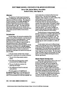
of DSMC including a multi-step forward translation between M ECHATRONICUML (MUML, [12]) as a high-level DSML for the software design of CPS, and the U PPAAL model checker [13]. Despite this multi-step forward translation, our approach allows to translate the counterexamples back to the DSML in one straightforward step, whereas the implementation of this back-translation is independent of the number of forward translation steps. We realize this by utilizing the model-to-model (M2M) traceability links of the forward translation, recorded by the model transformation engine. We evaluate our approach based on an example from the automotive domain. In particular, we show that our approach enables a correct translation and back-translation between MUML and U PPAAL. Moreover, we demonstrate that our approach provides helpful MUML counterexamples. In summary, the contribution of this paper is as follows: (i) We define and evaluate a DSMC for MUML using the model checker U PPAAL. (ii) We provide a transformation concept that enables a multi-step forward translation but only requires a single-step backward translation. Our paper is structured as follows: Section II summarizes the concept of MUML for verifying CPS based on a compositional verification approach. In particular, it shows the key role of DSMC in the context of this approach. In Section III, we explain our concept for complex DSMC scenarios by utilizing M2M traceability. Based on our concept, we explain our realization of the DSMC between MUML and U PPAAL in Section IV and evaluate it in Section V. Afterwards, we discuss related work in Section VI, before concluding the paper in Section VII. II. F OUNDATIONS : T HE C OMPOSITIONAL V ERIFICATION A PPROACH OF M ECHATRONICUML M ECHATRONICUML (MUML, [12], [14], [15]) is a DSML for specifying the discrete-event software of CPS at application level. Thereby, MUML particularly focuses on the specification of a component-based software architecture, the specification of self-adaptive behavior, and the applicationlevel communication protocols that are required to coordinate different systems. A typical example of a CPS that requires the aforementioned features is the coordination of an overtaking maneuver involving two cars as illustrated in Fig. 1. In this example, we use car-to-car (C2C) communication to coordinate and thereby to improve the safety of an overtaking maneuver. In our example, the red car (the overtaker) overtakes the yellow car (the overtakee) while the overtakee guarantees that it will not accelerate while it is being overtaken. Obviously, this scenario is safety-critical because an error in the communication protocol can result in an unsafe overtaking maneuver, e.g., if the overtakee assumes that it is not being overtaken but the overtaker assumes the contrary. In addition, we need to consider certain timing properties for the message exchange, e.g., for detecting lost messages based on timeouts. A major aim of MUML is to provide formal analyses for guaranteeing correctness of the specified model and thereby
Overtaker
Overtakee
Fig. 1. Coordinated Overtaking of Two Cars
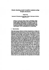
safety of the CPS. However, the software of a CPS typically consists of a multitude of concurrently executed components. As a result, applying formal methods like model checking [16] becomes quickly impossible due to the state explosion problem. A second obstacle is that the correctness of software components may depend on the physical environment of the CPS. This applies, in particular, to the feedback controllers of the system that control the movement of (parts of) a CPS like, e.g., the speed controller of the cars in Fig. 1. For such components, we are facing a so-called hybrid model checking problem [17] that is not solvable for realistic models using current techniques [18]. MUML strives for the best possible compromise between efficient simulation and formal correctness proofs for the software of a CPS. The resulting approach is twofold. First, we tackle the state-explosion problem by a compositional verification approach that we describe in more detail below. Second, we avoid hybrid verification by distinguishing between discrete software components and feedback controller components in the MUML component model [15]. For discrete software components, the developer specifies a state-based real-time behavior that is formally verified based on the compositional verification approach. Since the correctness of feedback controller components depends on the physical environment, the developer does not specify a behavior model in MUML, but in a control engineering tool like MATLAB/Simulink or Dymola/Modelica. For verifying and validating the correct integration of discrete software components and feedback controllers, the developer exports the verified discrete software components to the control engineering tool. Then, the developer can test the correctness of the feedback controllers and their integration with the discrete software components based on simulation [19], [20]. The core idea of MUML’s compositional verification approach [7], [12], which is illustrated in Fig. 2, is a syntactic decomposition of the software architecture into discrete software components and application-level communication protocols that define the interaction of the components. In MUML, we refer to these protocols as Real-Time Coordination Protocols (RTCPs). Each RTCP specifies the asynchronous message-based communication of two communicating partners called roles, while the behavior of each role is defined by a state-based real-time behavior. The RTCP for the coordinated overtaking includes the overtaker role and the overtakee role. Then, each port of a component (Car in our example) must
Components
Real-Time Coordination Protocol (RTCP)
1. Verify Real-Time Coordination Protocol via Model Checking |= φ1, …,φn AG ( stateActive(overtaker.overtaking) implies stateActive(overtakee.noA ccelar atio n) ); φ1
Overtaking overtaker buffer size: 5
«refines »
red:Car
dela y: 1 s
overtakee
2. Verify Refinement |= φ1, …,φn :overtakerCar
:overtakeeCar
buffer size: 5
«refines »
yellow:Car
3. Verify each Component Separately via Model Checking (at least for Deadlock Freedom)
Fig. 2. Overview of the Compositional Verification Approach
implement one role of an RTCP2 . As a result, the behavior of each port is defined by a state-based real-time behavior as well. Then, the decomposition of the software architecture enables the verification of the discrete software components of a CPS in three steps. In the first step, we verify all RTCPs w.r.t. safety, liveness, and reachability properties using model checking [16]. Therefore, the roles of the RTCP have to be specified independently of the components’ ports that implement them. The RTCP contains all relevant information for the communication, i.e., the exchanged messages, their timing, the size of the FIFO message buffers, and non-functional properties of the connection (e.g., message delay). The properties to be verified are specified in MTCTL (M ECHATRONICUML TCTL), which is a domain-specific variant of TCTL [21]. MTCTL is highly integrated with the behavior model of MUML. In our example, we require —among others— that the overtakee may not accelerate while the overtaker is still overtaking. Therefore, we define the property 1 in MTCTL as depicted at the top of Fig. 2. For performing the verification, the RTCP including all MTCTL properties needs to be translated to the model checker U PPAAL [13]. This translation is very complex as MUML defines several domain-specific aspects that U PPAAL does not provide, e.g., messages with parameters and timeconsuming actions. Moreover, counterexamples of the modelchecker must be translated back to the level of MUML in order to analyze them. The realization of both translations (forward and backward) in the form of a domain-specific model checking (DSMC) is the core contribution of this paper, as the existing work does not provide concepts for such complex scenarios. In the second step, we need to ensure that the ports of the components correctly refine the roles of the RTCPs, i.e., the implementation of the port does not violate any of the 2 In our example, we only provide one RTCP. However, in a fully realistic example, more RTCPs are necessary, e.g., for specifying the communications within a car and between cars and infrastructure.
properties that have been verified for the RTCP. This step is necessary because the implementation of a role’s behavior by a port typically requires adding data exchange with the other ports of the component, adding component-specific functions, and accessing shared variables inside the component. This step is covered in detail in [12]. In the third step, we need to verify that each component is free of deadlocks [22]. Such deadlocks may result from an incorrect interaction of the different ports inside the component. We may verify additional safety, liveness, and reachability properties referring to this interaction if necessary. In summary, we only need to consider one RTCP or one component at a time. This significantly improves the scalability of the verification and enables the formal verification of the software of a CPS. III. U TILIZING M2M T RACEABILITY FOR DSMC This section presents a DSMC approach that is suitable for the domain of CPS as it supports complex scenarios with larger differences between DSML and model checker. The applicability of our approach is the topic of Section IV by presenting our DSMC for MUML’s RTCPs using U PPAAL. We depict our approach in Fig. 3. Similar to already existing DSMC approaches [8], [9], [10], we apply model transformation techniques [23]. However, in contrast to the aforementioned DSMC approaches, we ease the task to overcome larger differences between the DSML and the input language of the model checker by allowing a multi-step translation (cf. [11]) but still only require a single-step backtranslation. We achieve this by utilizing the M2M traceability links that interrelate the models generated during the forward translation and therefore indicate the semantic correspondence between the input/output elements of each translation step. In fact, transformation languages such as QVTo [24] have a built-in traceability mechanism. Therefore, they do not require additional development effort in order to obtain these links while executing M2M transformations. Our approach starts with Activity 1 by applying the M2M translation from the design model given in terms of the DSML into the verification model that is based on the input language of the model checker. This translation may consist of multiple steps, e.g., our translation of RTCPs to the input language of the U PPAAL model checker consists of 13 steps. In each forward translation step, the aforementioned traceability links are automatically generated as an additional output. Activities 2-4 use state-of-the-art concepts: since existing model checkers usually operate on a textual input language, Activity 2 includes a model-to-text transformation of the verification model. For example, U PPAAL requires a serialization into an XML-based file format. Afterwards, the actual model checking takes place in Activity 3. Counterexamples generated during model checking are usually given in terms of a textual format as well. Therefore, Activity 4 includes a textto-model transformation. The resulting counterexample model is a sequence of snapshots. Each snapshot provides a runtime view of the verification model. Therefore, as depicted in Fig. 3,
Design Level
cross-references
Step 1
...
Verification Results + Counterexample Model Legend: Activity
Artifact
Data Flow
Legend Verification Model State Transition Runtime Snapshot
Textual Verification Input
Bidirectional Traceability Link
3. Automatic Verification Textual Verification Results + Textual Counterexamples 4. Text-to-Model
5. Single-Step Back-Translation (Model-to-Model)
Intermediate Model
2. Model-to-Text
Step n
Traceability Links
Design Model
Verification Model
1. Multi-Step Translation (Model-to-Model)
cross-references
Design Model
Verification Level
Two-Step Forward Translation
... ... Counterexample Model
...
... Single-Step Back-Translation
Counterexample Model
Cross-Reference e.g., to Indicate Active States
Fig. 4. Resolving of Traceability Paths
Verification Results and Counterexample Model
Reference
Fig. 3. Utilizing M2M Traceability for DSMC
the parsed counterexample model includes cross-references to the verification model. In our example application, these cross-references indicate which states of the U PPAAL timed automata are active in each particular snapshot. The back-translation in Activity 5 receives the counterexample model and translates it back to the DSML level. During the back-translation, all cross-references to elements of the verification model need to be replaced by corresponding cross-references to design model elements. To resolve this semantic correspondence, the back-translation also receives the traceability links generated during Activity 1 as an input. Since related approaches address only single-step translations [8], [9], [10], they are restricted to direct traceability links between design model and verification model. In contrast, our approach considers paths of traceability links with an arbitrary length, which traverse the intermediate models generated during a multi-step translation. A particular benefit of our approach is that the backtranslation does not depend on any conceptual or implementation details of the prior forward translation. It only depends on the meta models of the DSML and the model checker. Therefore our approach is independent of the concrete number of forward translation steps, i.e., it enables an easy integration of additional steps without changing the back-translation. Fig. 4 illustrates the analysis of traceability paths in the context of a forward translation consisting of two steps. In this example, a state machine inside the design model (consisting of two states) is translated to a verification model with two parallel state machines, and an overall amount of five states. The traceability links (depicted in blue) connect corresponding elements inside the design model, the intermediate model, and the verification model. The model checker’s counterexample model (depicted in the bottom right corner of Fig. 4) uses cross-references to indicate which states of the two state machines inside the verification model are active during each snapshot. For example, Fig. 4 highlights a single model
checker snapshot in red, which marks two states as active (one per state machine). In order to translate such a snapshot back to the DSML, the back-translation analyzes the traceability links generated in Activity 1. For example, for the two states marked active, it resolves the traceability path in the opposite direction, until the states contained by the original design model are reached. These states are semantically equivalent to the states marked active by the snapshot. In our example, the paths consist of two traceability links. However, we do not need two separate back-translations steps. Instead, we use a generic implementation of the back-translation that is independent of the number of traceability links that form the path. We realize it by resolving the traceability links incrementally until we reach an element of the design model. Thus, one single backtranslation step is sufficient to resolve traceability paths of arbitrary length. In our example, for the snapshot depicted in red, the traceability paths indicate that both active states inside the verification model evolved from one and the same state inside the design model. Thus, the back-translation generates a DSML snapshot that includes a cross-reference to mark this state active. The back-translation can therefore provide a DSML-specific runtime view of the original design model. Our approach is limited to 1:n traceability links between two models. Thus, every step may translate an input element to more than one output element. In order to avoid ambiguous resolving results, it must not be the case that two or more input elements are translated to the same output element. However, the translation from a DSML to the input language of a model checker is usually a refinement, i.e., it increases the number of model elements (cf. Fig. 4). Therefore, this aspect does not impose any practical restrictions. IV. DSMC FOR MUML’ S RTCP S USING U PPAAL In this section, we illustrate our DSMC between MUML’s RTCPs and the model checker U PPAAL. At first, we briefly introduce U PPAAL (cf. Section IV-A). Then, in Section IV-B, we explain MUML’s Real-Time Coordination Protocols (RTCPs) as well as our overtaking scenario in more detail. Afterwards, we present our DSMC: We show the model-to-model translation from RTCPs to U PPAAL in Section IV-C. Then, we
explain the automated invocation of U PPAAL in Section IV-D. Finally, we explain the model-to-model back-translation of counterexamples from U PPAAL to RTCPs in Section IV-E. We rely on the QVTo language [24] for all model-to-model transformations to utilize its traceability links in the backtranslation. Our implementation and our examples are open source and available for download on our website [25]. A. The Model Checker U PPAAL U PPAAL [13] is a tool for modeling and model checking real-time systems (such as CPS) based on networks of timed automata [26]. U PPAAL timed automata are state machines that consist of states, transitions, variables, and real-valued clocks3 . A clock measures the progress of time in a system. Time may only pass in states and not while firing a transition. Based on its clocks, a timed automaton enables to specify timedependent behavior using time guards, resets, and invariants. A time guard is a boolean constraint that is part of the enabling condition of a transition. A transition may only fire if the current clock values fulfill the time guard. Resets set a clock back to zero. An invariant is a boolean constraint on a state that must be fulfilled as long as the state is active. Timed automata are flat, i.e., they do not contain hierarchical states. Moreover, they may be composed to networks of timed automata that communicate in a synchronous fashion using socalled channels [27]. However —as a major drawback— U P PAAL does not provide modeling elements for the domain of CPS like asynchronous message-based communication (incl. message parameters) and time-consuming transitions. U PPAAL can verify a subset of the timed computation tree logic (TCTL, [21]), referred to as UTCTL in this paper. In particular, it supports three kinds of properties: reachability (something may happen), safety (“something bad will never happen” [27, p.8]), and liveness (“something will eventually happen” [27, p.9]). When verifying a property, U PPAAL generates the textual result (i.e., whether the property is fulfilled). Moreover, U PPAAL can —if available— generate textual traces. A trace is an execution path of the network of timed automata represented by a sequence of snapshots4 . Each snapshot contains the active state of all timed automata in the network and the values of all clocks and variables. A snapshot change occurs for three reasons: (i) time passes, (ii) a timed automaton fires a transition, or (iii) two timed automata synchronize using a common channel and synchronously fire their transitions. In particular, U PPAAL can produce a textual trace (1) if a reachability property is fulfilled or (2) if a safety or liveness property fails. In case (1), the trace leads to a snapshot where the property is fulfilled. In case (2), the trace leads to a snapshot where the property is violated. Therefore, a trace of case (2) is also called a counterexample. 3 In this paper, we use the terms states and transitions instead of U PPAAL ’s terminology of locations and edges to improve the understandability of our DSMC between MUML and U PPAAL. 4 In U PPAAL , snapshots are referred to as states. We use the term snapshot to avoid confusion with states of a RTSC (cf. Section IV-B).
B. RTCPs and the Overtaking Example In the following, we explain RTCPs in detail using the RTCP Overtaking, which we introduced in Section II. As we already stated before, its task is to specify a coordination between two cars by exchanging asynchronous messages under hard real-time constraints to enable a safe overtaking. Fig. 5 shows the RTCP Overtaking with its two roles overtaker and overtakee. As illustrated, each role of the RTCP may store five messages within its incoming message buffer received from the other role. The transmission delay (depicted at the role connector) for a message is 1 s. The state-based real-time behavior of each role is specified by a Real-Time Statechart (RTSC). RTSCs are a combination of timed automata and UML state machines [28]. Like timed automata, RTSCs may define clocks for expressing time constraints. Similar to UML but in contrast to U PPAAL’s timed automata, RTSCs enable to use, among others, (i) hierarchical compositions of states (including entry- and exit-points), (ii) entry- and exit-actions for states, (iii) composite transitions (a transition where the source or target is a hierarchical state), (iv) time-consuming transitions, and (v) asynchronous communication at transitions, i.e., consuming a received message from a buffer, or sending a message to the other role. The lower part of Fig. 5 shows the RTSCs for both roles of the RTCP Overtaking. A “/” separates a transition’s enabling conditions (a guard, a message to be received, and/or a clock constraint) from its effect (a sent message, a clock reset, and/or an action). The general behavior of the RTCP is as follows: First, the overtaker requests to overtake the overtakee by sending a request. At the same time, the overtaker resets the clock c when entering the requested state and awaits a response within six seconds as the state invariant is c 6 s. The overtakee replies by either an accept or decline message. If the overtakee accepts the request, it must drive with a constant speed (accelerating and braking are forbidden) to avoid a collision with the overtaker that will drive close to the overtakee before it starts to overtake. When receiving the accept message, the overtaker switches to overtaking.init and may accelerate. The transition between overtaking.init and overtaking.changed is time-consuming as it has a deadline of exactly 5 s. Thus, the overtaker has five seconds to change the lane and start the overtaking (for simplicity reasons, we assume that this is always possible). After exactly five seconds, the overtaker announces that it has changed the lane by sending a laneChanged message. From then on, the overtakee may brake, but may still not accelerate until a finish message announces that the overtaking has been carried out. Due to the invariant of state overtaking, the overtaker has to send message finish at most ten seconds after the overtaking has started (again, for simplicity reasons we assume that this is always possible). The behavior specified by a RTCP is typically safetycritical. For example, an error in the RTCP Overtaking may lead to an accident if the overtakee car accelerates even though the overtaking is still ongoing. Therefore, we
1. AG not deadlock 2. AG not bufferOverflow 3. AG (stateActive(overtaker.overtaking) implies stateActive(overtakee.noAcceleration)) 4. forall(s:States) EF stateActive(s)
Overtaking overtaker buffer size: 5
delay: 1s
clock c
overtaker
overtakee
overtaking invariant c 10s entry / {reset: c}
noOvertaking accept / requested / request invariant c 6s init [c 6s] entry / {reset: c}
noOvertaking
noAcceleration
clock c2 request /
/ laneChanged init changed deadline: 5s
decline /
overtakee buffer size: 5
init
/ decline
received invariant c2 3s entry / {reset: c2}
/ accept
request / finish /
noBraking laneChanged /
brakingAllowed
/ finish Legend
RTCP
Role
RTSC
Role Connector
State
Urgent Transition
Non-Urgent Transition
Entry Point
Exit Point
Fig. 5. MUML Real-Time Coordination Protocol Overtaking
Initial Model
After Deadline Normalization
A
deadline: 2-3s
B /m
C
After Hierarchy Normalization
B {reset: c} BC c 3s [c 2s] /m C
D D
[c_active]
A
A
D
B
Idle
Ex
ch!
{reset: c}
...
After UPPAAL Migration A ... Ex ... D C
Idle B BC c 3s
[c 2s] / m {c_active :=true}
ch? / {c_active :=false}
... ...
... BC send(m), ...
C Connector
C
... ... ... ...
Fig. 6. Multi-Step Translation from MUML to U PPAAL
need (domain-specific) model checking of RTCPs using U P PAAL. As a prerequisite, we specify properties of the RTCP to be verified using our textual formal language MTCTL (M ECHATRONICUML TCTL). The RTCP Overtaking defines four MTCTL properties: three safety and one reachability property (cf. Fig. 5). The first property states that the model contains no deadlock, while the second ensures that the message buffers never overflow. The third property states that whenever the overtaker is in state overtaking, the overtakee must be in state noAccelaration. Thus, it enforces the aforementioned requirement that the overtakee must not accelerate whenever the overtaking is in progress. The fourth property specifies that all states of the protocol are reachable. In the remainder of this section, we present our DSMC for MUML’s RTCPs using U PPAAL. C. Model-To-Model Translation from RTCPs to U PPAAL According to Activity 1 of our concept (cf. Fig. 3), we developed the model-to-model translation from RTCPs (including the MTCTL properties) to U PPAAL timed automata (including UTCTL properties). Due to the huge differences between RTCPs and U PPAAL, we separated our translation into 13 steps, each one addressing a particular concern of the RTCP and/or the MTCTL properties. Due to the limited size of this paper, we briefly explain three of these steps on a simplified example, which we depict
in Fig. 6 (we provide detailed information about all 13 steps in our technical report [29]). The first two steps that we illustrate are normalizations on the MUML level, i.e., they reduce the number of different modeling constructs. We do this in order to simplify the final step: the migration to U PPAAL. The first step normalizes deadlines by means of dedicated intermediate states, emulating the execution of timeconsuming transitions. In our example in Fig. 6, the deadline of the time-consuming transition from state B to C is replaced by a new clock c, the intermediate state BC (including an invariant) and two additional transitions. The invariant of state BC defines how long the intermediate state may be active. The clock constraint below defines when the transition to state C may fire. The recorded traceability links between the respective elements are depicted by blue dashed arrows. Our translation is a 1:n refinement, because each design model element is translated to one or more output elements. Another normalization applies a flattening concept, which is based on the work of David and M¨oller [30], transforming hierarchical RTSCs into flat ones. As a consequence, this translation splits the hierarchical RTSC into several flat RTSCs. Moreover, it replaces state entry- and exit-points, adds idle states (if a region may become inactive), and adds channels and global variables for synchronizing the behavior of different RTSCs (the variables indicate if a set of states is active, which allows exiting a hierarchy level). In our example, the results are two flat RTSCs. Moreover, we add an idle state to the lower RTSC, replace the exit-point by state Ex, and add one channel ch as well as one variable c active. Finally, our migration step replaces all remaining domain concepts, e.g., the asynchronous message exchange. Similar to Knapp et al. [6], we generate additional timed automata to encode the transmission connector (including properties such as message loss and delay) and the buffering of messages (including buffer overflow avoidance strategies). In our example, we have to transform the sending of message m when firing the transition from state BC to C into an U PPAAL function, and have to generate a connector such that the message can be sent. Moreover, we translate states, transitions, clocks, variables, and channels of MUML into their U PPAAL representation.
In summary, the translation shown in Fig. 6 is a refinement from one hierarchical RTSC to an U PPAAL model consisting of three timed automata and several hundred lines of code. All translation steps record bidirectional traceability links between semantically corresponding elements. For example, a bidirectional traceability path exists between the time-consuming transition from state B to C and the U PPAAL state BC. Beside the above translation of the RTSCs, we also translate the specified MTCTL properties to UTCTL. For example, the last property depicted in Fig. 5 (expressing that all states must be reachable) corresponds to twelve UTCTL properties, one for each state of the RTSCs because UTCTL does not support quantification over all states. D. Automated Invocation of U PPAAL Next, we implemented the Activities 2-4 (cf. Fig. 3) of our approach. In particular, we carried out Activity 2 by means of a model-to-text transformation using Xtend5 , generating U PPAAL’s XML-based input format for timed automata and the textual UTCTL properties. For Activity 3, we invoke U PPAAL’s command line verifier and obtain textual results and —if available— textual traces (e.g., a counterexample). As defined for Activity 4, we need to parse the textual (counterexample) trace into a model. Therefore, we defined a meta model for U PPAAL traces and developed a text-tomodel transformation using Xtext6 . The parsed trace model includes cross-references to the U PPAAL timed automata model. Among others, it reflects which states are active inside a particular snapshot and which values are assigned to clocks. E. Model-To-Model Back-Translation from U PPAAL to RTCPs As a basis for the model-to-model back-translation of traces (Activity 5 in Fig. 3), we defined a meta model for MUML traces as the target for our back-translation. Structurally, this meta model is similar to the (counterexample) trace meta model for U PPAAL, i.e., it provides means to model a sequence of snapshots (depicted in the middle of Fig. 7). However, these snapshots provide specific information of the original MUML design model at runtime, i.e., a MUML snapshot describes the active states and transitions inside RTSCs, the current values of variables and clocks, the contents of the message buffers, and which messages are currently in transit. Afterwards, we implemented a model-to-model transformation that translates U PPAAL snapshots back to MUML (see [29] for details of the implementation concept). Among others, we translate active U PPAAL states back to the corresponding active RTSC states or transitions. In order to traverse all the 13 forward translation steps inside a single backtranslation step, we resolve traceability links incrementally until we reach a MUML element (e.g., an RTSC state) that is part of the original RTCP. We carry out the resolving by means of QVTo’s invresolve operation [24], i.e., we utilize traceability links recorded automatically during the forward translation. As a result, we implemented the back-translation of the complete 5 https://eclipse.org/xtend/ 6 https://eclipse.org/Xtext/
(counterexample) trace in one single step, despite the 13 steps from MUML to U PPAAL. In particular, our back-translation is very small as it needs only 609 QVTo LOCs, compared to 9,239 LOCs for the translation from MUML to U PPAAL (ca. 7%). Moreover, the implementation was straighforward as we only had to define to which kind of MUML element a particular U PPAAL element needs to be transformed. Presently, (counterexample) traces are printed as SVG files. V. C ASE S TUDY We conduct a case study based on the guidelines by Kitchenham et al. [31] for evaluating our approach. A. Case Study Context The objective of our case study is evaluating if our DSMC for MUML’s RTCPs using the U PPAAL model checker (which is based on our general DSMC approach) is correct and if it provides helpful counterexamples at the level of MUML. We conduct our case study using 14 existing RTCPs of different interconnected transportation systems (e.g., cars, railways, robots). These RTCPs focus on various use cases for coordination, such as collision avoidance or our overtaking scenario. Within the paper, we show the evaluation of the RTCP Overtaking introduced in Section IV-B. The evaluation of all other RTCPs is provided on our website [25]. B. Setting the Hypothesis We only consider RTCPs that are —according to our expertise— initially correct w.r.t. their MTCTL properties. Then, we deliberately introduce errors in order force U PPAAL to produce counterexamples for defined safety or liveness properties expressed in MTCTL. Our case study has three evaluation hypotheses: (H1) Our DSMC approach correctly translates all RTCPs (incl. all MTCTL properties) to U PPAAL. (H2) Our DSMC approach correctly translates all U PPAAL counterexamples back to MUML. (H3) The MUML counterexamples help domain experts to detect the root cause of property violations. For evaluating hypothesis H1, we manually translate RTCPs that are correct w.r.t. their MTCTL properties to U PPAAL and compare them with the outputs of our automatic translation. Both should be equivalent. We evaluate hypothesis H2 similar to H1. Thus, we manually translate U PPAAL counterexamples back to MUML and compare them with the counterexamples that are back-translated automatically. Both sets should be equivalent as well. In addition, our DSMC should be able to provide a counterexample at the level of MUML for each U PPAAL counterexample. The MUML counterexample should only refer to elements of the original MUML design model. Concerning the evaluation of H3, we give the incorrect RTCP and the MUML counterexample to a domain expert that already has 1.5 years of experience in MUML. However, our domain expert has no knowledge of U PPAAL and does not know the root cause of the errors. We consider H3 as fulfilled, if the counterexample facilitates finding the root cause of the error for the domain expert.
Role overtaker
clock c1=1s
overtaker noOvertaking
Incoming Message Buffer: Empty
... decline /
overtaking invariant c ≤ 10s entry / {reset: c} init
...
...
...
overtaker. overtaking
overtaker
Trace Snapshot 1
Trace Snapshot 1
c
c
c
overtaker. noOvertaking
overtakee2 overtaker
overtaker2 overtakee c
Connector: No Message in Transit Role overtakee Incoming Message Buffer: Empty
...
...
Trace Snapshot n
Trace Snapshot n
c
+ 381 LOC in UPPAAL
overtakee noOvertaking ...
/ accept finish / request /
noAcceleration ...
AG (stateActive(overtaker.overtaking) implies stateActive(overtakee.noAcceleration))
c overtakee. noOvertaking
c
overtakee
c overtakee. noAcceleration
Fig. 7. Back-Translation of an U PPAAL Counterexample Trace to MUML
C. Preparing the Input Models First, we manually assure that all 14 RTCPs are correct w.r.t. their MTCTL properties according to the MUML semantics. Then, we manually create the 14 U PPAAL models. Next, we systematically introduce one modeling error into each RTCP. These errors include missing transitions, missing sent or received messages, inappropriate message delays, or false timeout periods. For each error, we define a reachability or safety property that is meant to reveal the error such that we get a counterexample for each RTCP. Finally, we manually create all 14 MUML counterexamples. For example, to produce a counterexample for the Overtaking RTCP, we insert an error to the RTSC of role overtaker (cf. Fig. 5). This RTSC encodes a response timeout using the invariant in state noOvertaking.requested and the transition leading from this state to noOvertaking.init. If this transition is fired, the overtaker assumes that the message was lost and, therefore, that the overtakee will not answer. We reduce the invariant of state noOvertaking.requested as well as the clock constraint of the transition that leads to state noOvertaking.init from 6 s to 4 s. This change violates the safety property 3, i.e., overtakee may accelerate during the overtaking. The reason for this is as follows: If the overtaker is in state noOvertaking.requested, it can return to state noOvertaking.init although the overtakee has switched to state noAcceleration and has sent an acceptance message that did not arrive yet. Then, the overtaker may change to state overtaking by sending a new request and consuming the accept message for the old request. Then, the overtakee will receive the new request message, which forces it to change back to the state noOvertaking.
translated back, the corresponding counterexamples match semantically, and the MUML counterexamples only refer to the original RTCPs. For example, our DSMC returned a valid counterexample when verifying the incorrect version of RTCP Overtaking with Property 3. Fig. 7 illustrates the counterexamples of U PPAAL and MUML for this property. In particular, the figure sketches the last snapshot of the counterexample for both languages. The correspondence (i.e., the traceability paths) between the modeling elements is highlighted using purple dashed arrows. Concerning the last MUML snapshot, the state overtaking.init and the transition from noAcceleration to noOvertaking are active which violates Property 3. Moreover, the snapshot shows that the incoming message buffers are empty, no message is in transit, and that clock overtaker.c1 is at 1s. Our domain expert was able to detect the root cause for every property violation based on the erroneous RTCP and the back-translated counterexample. Moreover, he stated that the back-translated counterexamples supported him in solving the problem (especially for complex protocols like Overtaking). For example, the domain expert was able to detect that the reduced timeout period in state overtaker.noOvertaking causes the violation depicted in Fig. 7. The counterexample correctly shows that overtakee accepts the overtaking, but overtaker switches back to noOvertaking.init before the accept message arrives due to the reduced invariant of c 4 s. This problem enables overtaker to send a second request message. This causes overtakee to switch from noAcceleration to noOvertaking, which violates the property.
D. Validating the Hypotheses For every correct RTCP, we execute our DSMC with all available MTCTL properties (including the one that is meant to indicate the error). As a result, we get valid U PPAAL models that correspond to our manually created ones. U PPAAL reports that they fulfill all defined MTCTL properties. For every erroneous RTCP, we execute our DSMC with the MTCTL property that is meant to indicate the error. As a result, we obtain valid MUML counterexamples for all RTCPs, i.e., the U PPAAL counterexamples were successfully
Our case study demonstrates that our DSMC correctly translates from MUML to U PPAAL, and U PPAAL counterexamples back to MUML. Hence, we consider our first and second evaluation hypotheses as fulfilled. The back-translated counterexamples allowed to identify the root cause of all property violations. Hence, we consider our third evaluation hypothesis as fulfilled as well. In our case study, the most important threats to validity are as follows: (1) We might have made mistakes in our manual translations (forward and backward) and when comparing the
E. Analyzing the Results
results. Thus, the translations might be in fact incorrect. (2) We only considered 14 RTCPs and introduced only one error in each RTCP. Even though we consider this example as realistic, other realistic protocols, properties, and errors could exist that are not correctly translated. (3) It might be an exception that our domain expert found all errors. Other domain experts could be less successful. Moreover, the errors might have been too easy to identify. (4) We cannot precisely state how much influence our back-translated counterexamples had on our domain expert for finding the errors. VI. R ELATED W ORK Several concepts towards model checking of CPS exist, which support a translation from a DSML towards a model checker, e.g., COMDES-II [4], RT-DEVS [5], Dragomir et al. [32], AADL [33], Tiwari et al. [34], HUGO/RT [6], and the Compositional Interchange Format (CIF) [35]. However, they all do not provide concepts for back-translating counterexamples. In the scope of this paper, we rather discuss related work that fully hides formal methods by providing a back-translation for counterexamples. We restrict ourselves to approaches that establish a close link between counterexamples and design model, creating explicit cross-references. An extended discussion of related work may be found in our technical report [29]. Molotnikov et al. [36] address the verification of domainspecific extensions to the C programming language. The verification is achieved by a multi-step translation to a basic form of verifiable C. By utilizing traceability information, the verification results are translated back to the domain-specific level. In contrast to our approach, a conceptual consideration of the back-translation is not in the scope of their paper. Guerra et al. [8] present the BaVeL DSML for the modeling of DSMC workflows including back-translations. The language uses triple graphs [37] for the specification of translation rules. During the forward translation, these rules produce the required traceability links that are later used by the back-translation. However, in case of multi-step translations, the approach requires a multi-step back-translation as well, because each step of the forward translation must be traced back individually by means of a separate triple graph. In contrast, our approach enables a single-step back-translation that is independent of the number of forward translation steps. Zalila et al. [38] provide a methodology for DSMC that is based on a metamodeling pattern for executable DSMLs. Shah et al. [10] present a translation of structural UML models to Alloy for static consistency analysis. The authors use a meta transformation to generate the actual back-translation on-thefly from the recorded traceability links. The MADES approach by Baresi et al. [9] uses traceability only to highlight the correspondences between counterexample elements and the equivalent elements of the design model (without providing a proper back-translation). Common to these three approaches is that they require an additional instrumentation of the forward translation to produce a specific kind of traceability output. Thus, transformation developers need to enrich the basic translation with additional traceability logic. Especially in case
of multi-step translations, enriching a model transformation manually implies a huge development effort. In contrast, our approach demonstrates that traceability links generated implicitly by the transformation engine are sufficient even in case of multi-step translations. Combemale et al. [39] provide a generic approach for the back-translation of execution traces such as counterexamples, but require a formal definition of the operational DSML semantics. Heged¨us et al. [40] apply traceability links for the back-translation, but require the operational semantics of the DSML and the verification formalism (e.g., a model checker input language) to be formalized in terms of graph transformations. Thus, in contrast to our approach, both require a formalization of the operational DSML semantics. However, DSMLs such as MUML are often equipped with informal semantics, such that a complete formal semantics definition at DSML level represents an additional burden. VII. C ONCLUSION AND F UTURE W ORK In this paper, we provide a DSMC in the context of CPS between MUML’s RTCPs and the model checker U PPAAL. In contrast to related work that supports model checking of CPS, we enable the back-translation of counterexamples and support the relevant aspects of CPS-specific communication protocols at application level. We realize this DSMC using a new concept that enables the usage of multi-step forward translations but still only needs a single-step back-translation. In our general DSMC concept, we propose to utilize the traceability links of the forward translation that are automatically provided by the model transformation engine. These links enable us to identify the corresponding model elements between the design and the verification model, independently of the concrete implementation of the forward translation. In a case study, we showed that our DSMC between MUML’s RTCPs and U PPAAL enables a correct translation and back-translation, and that it is able to provide helpful counterexamples. Transformation developers should benefit from our approach when implementing new DSMC solutions, as they can split up the translation into multiple steps and only need few LOCs for the implementation of the back-translation. These benefits should reduce their development time and should lead to a maintainable solution. Authors of related approaches can use our complex application scenario to evaluate their work, since our implementation is open source [25] and the specifications of MUML [15] and U PPAAL [13] are publicly available. Future work will further evaluate our general approach on other complex applications scenarios. Moreover, we will further evaluate our DSMC between MUML and U PPAAL in order to find out if our approach reduces the maintainability in comparison to related work. ACKNOWLEDGMENTS We thank Marie C. Platenius and J¨org Holtmann for feedback on drafts of the paper, and Goran Piskachev for his help in our case study. Christopher Gerking is member of the PhD
program “Design of Flexible Work Environments — HumanCentric Use of Cyber-Physical Systems in Industry 4.0”, supported by the federal state of North Rhine-Westphalia. R EFERENCES [1] E. M. Clarke, O. Grumberg, and D. A. Peled, Model Checking. MIT Press, 2000. [2] J. A. Davis, M. Clark, D. D. Cofer, A. Fifarek, J. Hinchman, J. Hoffman, B. Hulbert, S. P. Miller, and L. Wagner, “Study on the barriers to the industrial adoption of formal methods,” in Formal Methods for Industrial Critical Systems, ser. LNCS, C. Pecheur and M. Dierkes, Eds., vol. 8187. Springer, 2013, pp. 63–77. [3] W. Visser, M. B. Dwyer, and M. W. Whalen, “The hidden models of model checking,” Software & Systems Modeling, vol. 11, no. 4, pp. 541–555, 2012. [4] X. Ke, P. Pettersson, K. Sierszecki, and C. Angelov, “Verification of COMDES-II systems using U PPAAL with model transformation,” in Proc. 14th IEEE International Conference on Embedded and Real-Time Computing Systems and Applications. IEEE, 2008, pp. 153–160. [5] A. Furfaro and L. Nigro, “Embedded control systems design based on RT-DEVS and temporal analysis using U PPAAL,” in Proc. of the International Multiconference on Computer Science and Information Technology, M. Ganzha, M. Paprzycki, and T. Pełech-Pilichowski, Eds., vol. 3. IEEE, 2008, pp. 601–608. [6] A. Knapp, S. Merz, and C. Rauh, “Model checking timed UML state machines and collaborations,” in Formal Techniques in Real-Time and Fault-Tolerant Systems, ser. LNCS, W. Damm and E.-R. Olderog, Eds., vol. 2469. Springer, 2002, pp. 395–416. [7] H. Giese, M. Tichy, S. Burmester, W. Sch¨afer, and S. Flake, “Towards the compositional verification of real-time UML designs,” in Proc. of the 11th ACM SIGSOFT Symposium on Foundations of Software Engineering. ACM, 2003, pp. 38–47. [8] E. Guerra, J. de Lara, A. Malizia, and P. D´ıaz, “Supporting user-oriented analysis for multi-view domain-specific visual languages,” Information and Software Technology, vol. 51, no. 4, pp. 769–784, 2009. [9] L. Baresi, G. Blohm, D. S. Kolovos, N. Matragkas, A. Motta, R. F. Paige, A. Radjenovic, and M. Rossi, “Formal verification and validation of embedded systems: the UML-based MADES approach,” Software & Systems Modeling, vol. 14, no. 1, pp. 343–363, Feb. 2015. [10] S. M. A. Shah, K. Anastasakis, and B. Bordbar, “From UML to Alloy and back again,” in Models in Software Engineering, ser. LNCS, S. Ghosh, Ed., vol. 6002. Springer, 2010, pp. 158–171. [11] A. Etien, V. Aranega, X. Blanc, and R. F. Paige, “Chaining model transformations,” in Proc. of the First Workshop on the Analysis of Model Transformations. ACM, 2012, pp. 9–14. [12] C. Heinzemann, C. Brenner, S. Dziwok, and W. Sch¨afer, “Automatabased refinement checking for real-time systems,” Computer Science Research and Development, vol. 30, no. 3, pp. 255–283, Aug. 2015. [13] J. Bengtsson, K. G. Larsen, F. Larsson, P. Pettersson, and W. Yi, “U PPAAL- a tool suite for automatic verification of real-time systems,” in Verification and Control, ser. LNCS, R. Alur, T. A. Henzinger, and E. D. Sontag, Eds., vol. 1066. Springer, 1996, pp. 232–243. [14] S. Becker, S. Dziwok, C. Gerking, C. Heinzemann, W. Sch¨afer, M. Meyer, and U. Pohlmann, “The M ECHATRONICUML method: Model-driven software engineering of self-adaptive mechatronic systems,” in Companion Proc. of the 36th International Conference on Software Engineering. ACM, 2014, pp. 614–615. [15] S. Becker, S. Dziwok, C. Gerking, C. Heinzemann, S. Thiele, W. Sch¨afer, M. Meyer, U. Pohlmann, C. Priesterjahn, and M. Tichy, “The M ECHATRONICUML design method — process and language for platform-independent modeling,” Software Engineering Group, Heinz Nixdorf Institute, University of Paderborn, Tech. Rep. tr-ri-14-337, Mar. 2014. [16] C. Baier and J.-P. Katoen, Principles of Model Checking. MIT Press, 2008. [17] T. A. Henzinger, “The theory of hybrid automata,” in Proc. 11th Annual IEEE Symposium on Logic in Computer Science. IEEE, Jul. 1996, pp. 278–292. [18] A. Eggers, N. Ramdani, N. S. Nedialkov, and M. Fr¨anzle, “Improving the SAT modulo ODE approach to hybrid systems analysis by combining different enclosure methods,” Software & Systems Modeling, vol. 14, no. 1, pp. 121–148, Feb. 2015.
[19] C. Heinzemann, J. Rieke, and W. Sch¨afer, “Simulating self-adaptive component-based systems using MATLAB/Simulink,” in Proc. 2013 IEEE 7th International Conference on Self-Adaptive and Self-Organizing Systems. IEEE, 2013, pp. 71–80. [20] U. Pohlmann, J. Holtmann, M. Meyer, and C. Gerking, “Generating Modelica models from software specifications for the simulation of cyber-physical systems,” in Proc. 2014 40th EUROMICRO Conference on Software Engineering and Advanced Applications. IEEE, 2014, pp. 191–198. [21] R. Alur, C. Courcoubetis, and D. L. Dill, “Model-checking in dense realtime,” Information and Computation, vol. 104, no. 1, pp. 2–34, 1993. [22] H. Giese, “A formal calculus for the compositional pattern-based design of correct real-time systems,” Software Engineering Group, University of Paderborn, Tech. Rep. tr-ri-03-240, Jul. 2003. [23] S. Sendall and W. Kozaczynski, “Model transformation: The heart and soul of model-driven software development,” IEEE Softw., vol. 20, no. 5, pp. 42–45, 2003. [24] Object Management Group, MOF 2.0 Query/View/Transformation Specification, Feb. 2015, no. formal/15-02-01. [25] [Online]. Available: https://trac.cs.upb.de/mechatronicuml/wiki/ PaperModevva2015 [26] J. Bengtsson and W. Yi, “Timed automata,” in Lectures on Concurrency and Petri Nets, ser. LNCS, J. Desel, W. Reisig, and G. Rozenberg, Eds. Springer, 2004, vol. 3098, pp. 87–124. [27] G. Behrmann, A. David, and K. G. Larsen, A Tutorial on U PPAAL 4.0, Department of Computer Science, Aalborg University, Nov. 2006. [28] Object Management Group, OMG Unified Modeling Language, Mar. 2015, no. formal/15-03-01. [29] S. Dziwok, C. Gerking, and C. Heinzemann, “Domain-specific model checking of M ECHATRONICUML models using U PPAAL,” Software Engineering Group, Heinz Nixdorf Institute, University of Paderborn, Tech. Rep. tr-ri-15-346, Jul. 2015. [30] A. David, M. O. M¨oller, and W. Yi, “Formal verification of UML statecharts with real-time extensions,” in Fundamental Approaches to Software Engineering, ser. Lecture Notes in Computer Science, R.-D. Kutsche and H. Weber, Eds., vol. 2306. Springer, 2002, pp. 218–232. [31] B. Kitchenham, L. Pickard, and S. L. Pfleeger, “Case studies for method and tool evaluation,” IEEE Softw., vol. 12, no. 4, pp. 52–62, Jul. 1995. [32] I. Dragomir, I. Ober, and C. Percebois, “Contract-based modeling and verification of timed safety requirements within SysML,” Software & Systems Modeling, Jul. 2015. [33] A. Johnsen, K. Lundqvist, P. Pettersson, and O. Jaradat, “Automated verification of AADL-specifications using U PPAAL,” in Proc. 2012 IEEE 14th International Symposium on High-Assurance Systems Engineering. IEEE, 2012, pp. 130–138. [34] A. Tiwari, N. Shankar, and J. M. Rushby, “Invisible formal methods for embedded control systems,” Proc. IEEE, vol. 91, no. 1, pp. 29–39, Jan. 2003. [35] D. E. Nadales Agut, M. A. Reniers, R. R. Schiffelers, K. Y. J¨orgensen, and D. van Beek, “A semantic-preserving transformation from the compositional interchange format to U PPAAL,” in Proc. of the 18th IFAC World Congress, S. Bittanti, A. Cenedese, and S. Zampieri, Eds., 2011, pp. 12 496–12 502. [36] Z. Molotnikov, M. V¨olter, and D. Ratiu, “Automated domain-specific C verification with mbeddr,” in Proc. of the 29th ACM/IEEE International Conference on Automated Software Engineering, I. Crnkovic, M. Chechik, and P. Gr¨unbacher, Eds. ACM, 2014, pp. 539–550. [37] A. Sch¨urr, “Specification of graph translators with triple graph grammars,” in Graph-Theoretic Concepts in Computer Science, ser. LNCS, E. W. Mayr, G. Schmidt, and G. Tinhofer, Eds., vol. 903. Springer, 1995, pp. 151–163. [38] F. Zalila, X. Cr´egut, and M. Pantel, “Formal verification integration approach for DSML,” in Model-Driven Engineering Languages and Systems, ser. LNCS, A. Moreira, B. Sch¨atz, J. Gray, A. Vallecillo, and P. Clarke, Eds. Springer, 2013, vol. 8107, pp. 336–351. [39] B. Combemale, L. Gonnord, and V. Rusu, “A generic tool for tracing executions back to a DSML’s operational semantics,” in Modelling Foundations and Applications, ser. LNCS, R. B. France, J. M. K¨uster, B. Bordbar, and R. F. Paige, Eds., vol. 6698. Springer, 2011, pp. 35–51. ´ Heged¨us, G. Bergmann, I. R´ath, and D. Varr´o, “Back-annotation of [40] A. simulation traces with change-driven model transformations,” in 2010 8th IEEE International Conference on Software Engineering and Formal Methods, J. L. Fiadeiro, S. Gnesi, and A. Maggiolo-Schettini, Eds. IEEE, 2010, pp. 145–155.