purpose of this work is to describe such a procedure for the class of so-called sequential ... solution while any composite design is attained as the limit of a sequence of ... viewed as topology optimization methods (see e.g. [2], [3], [7], [8], [11], [12]). ..... vances in Mathematical Sciences and Applications, Gakkotosho, Tokyo, 4,.
SHAPE OPTIMIZATION WITH GENERAL OBJECTIVE FUNCTIONS USING PARTIAL RELAXATION Gr´egoire ALLAIRE, Sylvie AUBRY Laboratoire d’Analyse Num´erique Universit´e Paris 6 4, place Jussieu 75252 Paris Cedex 05, France Fran¸cois JOUVE Centre de Math´ematiques Appliqu´ees (UMR 7641) Ecole Polytechnique 91128 Palaiseau, France
1
Introduction
The homogenization method for topology optimization in structural design is by now well established (see [2], [3], [7], [8], [15], [16], [17], [18] and references therein). However, the theory is restricted to compliance or eigenfrequency optimization (in the single or multiple loadings case). The problem is that optimal microstructures are unknown for general objective functions. Of course, in numerical practice, many generalizations have appeared: they often rely on the use of fictitious materials (so-called power-law materials, see e.g. [18]) or of sub-optimal materials (for example, obtained by homogenization of a perforated periodic cell). Working with a subclass of microstructures is called a partial relaxation of the problem. This subclass needs to be rich enough in order to approximate as much as possible the true optimal microstructures, which yields good numerical properties (fast convergence, global minima). On the other hand it must be as explicit as possible for a good efficiency. The idea of partial relaxation is not new but somehow has never been explored systematically. The purpose of this work is to describe such a procedure for the class of so-called sequential laminates (of any order) which are delivered by an explicit formula and are optimal in a number of important cases. We describe the numerical implementation of this method of partial relaxation and discuss its application on several examples. Part of this work was written up in Aubry’s thesis [5].
2
Setting of the problem
We consider a bounded domain Ω ∈ IRN , with N = 2 or 3, occupied by two linearly elastic isotropic phases A and B. Their Hooke’s laws are also denoted
1
by A and B and satisfy for any symmetric matrix ξ � � � � 2µA 2µB Aξ = 2µA ξ + κA − (trξ) I2 , Bξ = 2µB ξ + κB − (trξ) I2 , N N where 0 < µA < µB are the shear moduli and 0 < κA < κB are the bulk moduli. It is convenient to introduce a Lam´e coefficient, proportional to the Poisson’s ratio, defined by 2µB 2µA , λB = κ B − . λA = κ A − N N Let χ ∈ L∞ (Ω; {0, 1}) be the characteristic function of phase A. We define an overall Hooke’s law in Ω by Aχ = χA + (1 − χ)B. The corresponding displacement uχ of this structure is computed as the unique solution in H01 (Ω)N of � − div (Aχ e(uχ )) = f in Ω uχ = 0 on ∂Ω, where e(uχ ) = (∇u + ∇t u)/2 is the strain tensor, and f is a given body force in L2 (Ω)N (for simplicity, we have chosen to work with a model problem with Dirichlet boundary conditions, but more general surface loadings or boundary conditions are possible). We address the following two-phase optimal design problem (shape optimization corresponds to the degenerate limit A → 0) inf
χ∈L∞ (Ω;{0,1})
J(χ),
(1)
with an objective function J defined by Z Z [χ(x)gA (x, uχ (x)) + (1 − χ(x))gB (x, uχ (x))] dx + ` χ(x)dx, J(χ) = Ω
Ω
where ` is a Lagrange multiplier for a volume constraint on phase A, and gA , gB are smooth functions with suitable growth. It is a classical matter to show that (1) is an ill-posed problem which requires relaxation, i.e. for which there exist only generalized optimal solutions (see e.g. [15], [17]). These generalized designs are defined as composite materials obtained by mixing on a microscopic scale the two phases A and B. The composite materials are parametrized by two functions: the density θ(x) ∈ [0, 1] of phase A and the microstructure or geometric arrangement of the two phases (yielding different effective Hooke’s laws A∗ (x)) at each point x ∈ Ω. By homogenization theory, the relaxed formulation of (1) turns out to be min
(θ,A∗ )∈CD
J ∗ (θ, A∗ ),
2
(2)
with an extended objective function Z (θgA (x, u) + (1 − θ)gB (x, u) + `θ) dx, J ∗ (θ, A∗ ) =
(3)
Ω
where u(x) is the unique solution in H01 (Ω)N of the homogenized problem � − div (A∗ e(u)) = f in Ω, (4) u=0 on ∂Ω, and CD is the space of generalized or composite designs � CD = θ ∈ L∞ (Ω; [0, 1]) , A∗ (x) ∈ Gθ(x) ∀x ∈ Ω ,
(5)
where, for each constant value 0 ≤ θ ≤ 1, Gθ is the set of all homogenized Hooke’s law obtained by mixing the phases A and B in proportions θ, 1 − θ. The advantages of the relaxed formulation (2) are numerous and well described in e.g. [3], [15], [16], [17]. In particular, it always admits an optimal solution while any composite design is attained as the limit of a sequence of classical designs. This implies that relaxation does not change the problem but makes it well-posed, and that a nearly optimal classical design can easily be recovered from an optimal composite design by a suitable penalization process. There are also many numerical algorithms based on this approach that can be viewed as topology optimization methods (see e.g. [2], [3], [7], [8], [11], [12]). There is however one serious disadvantage with the relaxed formulation (2) since the set Gθ of all composite materials is unknown. In a few special cases (of great practical importance), the optimality conditions allows to replace G θ by its explicit subset of so-called sequential laminates. This is possible if the objective function J and J ∗ is the compliance or the first eigenfrequency (or even a sum of several of them, see e.g. [1], [4]). In such a case, (2) is truly useful and fully explicit. Unfortunately, in all other cases (which are the vast majority of choices of the functions gA , gB ), this relaxed formulation is useless since we have no knowledge of this set Gθ of composite materials. By opposition to what follows, we shall call (2) a fully relaxed formulation.
3
Partial relaxation
To obtain a tractable formulation, we restrict Gθ to its explicit subset L+ θ of all sequential laminates A∗ , with core A and matrix B, in proportions θ and (1 − θ) respectively, defined by formula (6). For a number q of laminations and unit lamination directions Pq (ei )1≤i≤q , as well as lamination parameters (mi )1≤i≤q satisfying mi ≥ 0 and i=1 mi = 1, a sequential laminate A∗ is defined by θ (A∗ − B)−1 = (A − B)−1 + (1 − θ)
q X i=1
3
mi fB (ei ),
(6)
where fB (ei ) is given by fB (e)ξ : ξ =
� 1 1 (ξe · e)2 . |ξe|2 − (ξe · e)2 + µB 2µB + λB
We introduce a set LD + of sequentially laminated designs, defined by n o LD+ = θ ∈ L∞ (Ω; [0, 1]) , A∗ (x) ∈ L+ ∀x ∈ Ω . θ(x)
(7)
(8)
The proposed partial relaxation is inf
(θ,A∗ )∈LD +
J ∗ (θ, A∗ ),
(9)
with the same objective function J ∗ defined by (3). A priori, the existence of a minimizer of the partial relaxation (9) is not guaranteed, which is the main difference with the full relaxation (2). It seems that we have gain very little in replacing the ill-posed problem (1) by another ill-posed problem (9). Nevertheless, loosely speaking the latter is less ill-posed than the former since its integrand has been smoothed or averaged, at least partially, leading to better convexity properties. The question of how much qualitatively the partial relaxation improves on the original formulation is linked to the question of how far from optimal are the microstructures in L+ θ . As a possible justification of this partial relaxation (9), let us simply recall that in the cases of compliance or eigenfrequency optimization it coincides with the full relaxation. The advantage of dealing with generalized designs in LD + , instead of CD, is that we can find optimality conditions which amounts to compute the derivative of the objective function and builds numerical gradient algorithms. We first compute the derivatives of J ∗ in the continuous case. For this purpose we first need to obtain a convenient continuous parameterization of the set L+ θ of sequential laminates. Introducing a probability measure ν defined by ν(e) =
q X
mi δ(e − ei )
i=1
where δ is the Dirac mass at the origin, any sequential laminate A∗ in L+ θ is parametrized by the proportion θ of phase A and by this probability measure ν (positive with unit mass). More precisely, following [6], one can show that ∗ L+ θ is the set of all symmetric fourth-order tensors A such that there exists a probability measure ν on the unit sphere SN −1 = {e ∈ IRN , |e| = 1} satisfying Z −1 −1 fB (e) dν(e), (10) θ (A∗ − B) = (A − B) + (1 − θ) SN −1
with fB (e) defined by (7). Recall that a probability measure ν on SN −1 must be R non-negative, ν(e) ≥ 0, and of unit mass, SN −1 dν(e) = 1. We therefore view θ 4
and ν as the true independent design parameters in LD + . In other words, the partial relaxation (9) is equivalent to inf {J ∗ (θ, ν) = J ∗ (θ, A∗ (θ, ν))} .
(θ,ν)
One can compute the partial derivatives of J ∗ by introducing an adjoint state p which is the solution of � ∂gB A − div (A∗ e(p)) = θ ∂g ∂u (x, u) + (1 − θ) ∂u (x, u) in Ω (11) p=0 on ∂Ω. The objective function J ∗ (θ, ν) is differentiable, and denoting by δθ and δν admissible increments, its directional derivative is Z Z Z δJ ∗ (θ, ν) = ∇θ J ∗ δθ dx + ∇ν J ∗ d(δν) dx, (12) Ω
Ω
SN −1
with the partial derivatives ∇θ J ∗ (x) = gA (x, u(x)) − gB (x, u(x)) + ` + ∇ν J ∗ (x, e) = and
∂A∗ (x) ∂θ
∂A∗ e(u) : e(p), ∂θ
∂A∗ (x, e)e(u) : e(p), ∂ν
� � R = T −1 (A − B)−1 + SN −1 fB (e) dν(e) T −1 ,
∂A∗ (x, e) ∂ν
= −θ(1 − θ)T −1 fB (e)T −1 ,
T
= (A − B)−1 + (1 − θ)
R
SN −1
fB (e) dν(e) .
This gives the basis for a numerical gradient method which is described in the next section. Of course, since θ, ν are constrained locally at each point x (θ must stay in the range [0, 1], and ν is a probability measure) the gradient method must be combined with a projection step to satisfy these constraints. For simplicity we focused on the case of a single load optimization problem. There is obviously no difficulty in extending the previous analysis to multiple load problems. This approach can also be extended to problems where the objective function involves strain or stress tensors. This causes additional difficulties since one need so-called corrector results to define the generalized or relaxed objective functions. However, these correctors are explicitly known for laminates (see [9]). We will report on this topic in a future work.
5
4
Numerical algorithm
To obtain a numerical method we must, as usual, discretize in space the design variables θ and ν, but the measure ν must also be discretized with respect to its second argument, the unit vector e. Therefore, we discretize the unit sphere SN −1 by a number q of fixed directions (ej )1≤j≤q , and we replace the ”continuous” measure ν by a ”discrete” measure which is a sum of Dirac masses νdiscrete (e) =
q X
mi δ(e − ei )
(13)
i=1
Pq where (mi )1≤i≤q is a collection of parameters satisfying mi ≥ 0 and i=1 mi = 1. Of course, this amounts to replace the ”continuous” lamination formula (10) by its ”discrete” analogue (6). In order to keep a small number of directions q (of the order of 4 in practice) and yet have good results, we can also introduce a global rotation of the microstructure, namely use the following rotated version of (6) q X −1 −1 mj Rt fB (ej )R . (14) θ (A∗ − B) = (A − B) + (1 − θ) j=1
where R is the fourth order tensor corresponding to a rotation matrix Q in the physical space (with Q−1 = Qt ), i.e. Rξ = Q−1 ξQ for any symmetric matrix ξ. This introduces another design parameter, denoted by φ, which corresponds to one angle in 2-D or two angles in 3-D necessary to parameterize a rotation Q(φ) in the physical space. Adding this rotation parameter φ requires the computation of another partial derivative of J ∗ which is easily seen to be ∇φ J ∗ (x) =
∂A∗ (x)e(u) : e(p), ∂φ
with ∂A∗ ∂φ
−1 = −θ(1 − θ)T −1 ∂M , ∂φ T
T (φ)
= (A − B)−1 + (1 − θ)
M (φ) = Rt (φ)
�P
q j=1
Pq
j=1
mj Rt (φ)fB (ej )R(φ),
� mj fB (ej ) R(φ).
Upon discretization of the unit sphere SN −1 , a measure ν is now completely determined by the vector m = (mi )1≤i≤q which appears in (13). Therefore, the partial derivative ∇ν J ∗ is replaced by ∇m J ∗ (x) =
∂A∗ (x)e(u) : e(p), ∂m 6
(15)
with ∂A∗ = ∂m
�
∂A∗ ∂mi
�
= −θ(1 − θ)T −1 Rt fB (ei )RT −1 1≤i≤q
�
1≤i≤q
.
Recall that (13) is a probability measure if the vector m satisfies mi ≥ 0 and P q i=1 mi = 1. This gives the required projection for the gradient algorithm. We now have all the ingredients to define the proposed numerical algorithm. 1. Initialization of the design parameters θ0 , φ0 , m0 (for example, we take them constant satisfying the constraints). 2. Iteration until convergence, for k ≥ 0: (a) Computation of the state uk and the adjoint state pk , solutions of (4) and (11) respectively, with the previous design parameters θk , φk , mk . (b) Updating of these parameters by θk+1
= max (0, min (1, θk − tk ∇θ Jk∗ )) ,
φk+1
= φk − tk ∇φ Jk∗ ,
mi,k+1
= max (0, mi,k − tk ∇mi Jk∗ + `k ) .
where `P k is a Lagrange multiplier (iteratively adjusted) for the conq straint i=1 mi,k = 1, and tk > 0 is a small step such that J ∗ (θk+1 , φk+1 , mk+1 ) < J ∗ (θk , φk , mk ).
A good descent step tk is computed through a line search that may be expensive since each evaluation of the objective function requires the solution of ∗ the direct and adjoint equation. In practice, we stop as soon as Jk+1 ≤ Jk∗ and we divide the step by two if not. Of course, more clever optimization schemes could be used (see e.g. [20]).
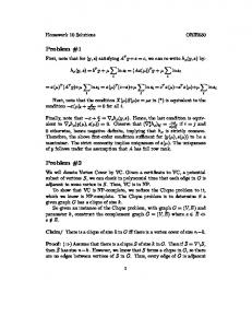
Figure 1: Boundary conditions for the cantilever problem. We have tested this numerical method on various 2-D problems (3-D would work as well). Several objective functions are available (see e.g. the design of 7
compliant mechanisms in [19]). Here we restrict ourselves to the minimization of the displacement field. The Young modulus of material B is normalized to 1 and its Poisson ratio is fixed to 0.3. Material A is assumed to be void, and to avoid degeneracy the lowest admissible value of the material density (1−θ) is 10 −3 .The algorithm is initialized with a working domain full of material (θ0 = 0). We study a medium cantilever problem (see the boundary conditions on Figure 1): the domain size is 20 × 10 discretized with a rectangular 120 × 60 mesh, and the Lagrange multiplier ` is iteratively adjusted so that the weight of the structure is constrained to be 40% of that of the full working domain. We minimize the Lm (Ω)-norm of the displacement, which corresponds to the following choice: gA (x, u) = 0 and gB (x, u) = |u|m . In truth, the objective function is rescaled in order to avoid the effects of rounding errors for large values of m, i.e. we minimize �Z � 1/m
J ∗ (θ, A∗ ) =
(1 − θ)|u|m dx
,
Ω
with a volume constraint. As expected, the ”composite” solutions (i.e. the numerical output of the partial relaxation) exhibit large areas of intermediate densities (which indicates that in practice the laminated composites are often optimal for this problem). To recover classical designs (i.e. with pure material and void) we apply a penalization procedure as in e.g. [2], [21] which forces the density θ to take only the values 0 or 1. We tried two different penalization procedures. The first one amounts to add a penalizing term to the standard objective function J ∗ (θ, A∗ ) of the type Z cpen (1 − θ)q θq dx Ω
where cpen is a positive constant and q is an exponent larger or equal to 1. We prefer a second more efficient procedure which changes the lamination formula giving the value of the homogenized tensor A∗ . Instead of (6) (or its rotated version (14)) we use θq (A∗ − B)−1 = (A − B)−1 + (1 − θq )
q X
mi fB (ei ),
(16)
i=1
where q > 1 is typically 3 or 5. The effect of (16) is that the resulting ”fictitious” composite A∗ is much weaker than the usual laminate. Therefore, it is not advantageous to use any such composite of intermediate density. Using the modified formula (16) results in a very effective penalization scheme: almost all grey areas in the homogenized design disappear to yield a black and white ”penalized” design as can be seen in the following pictures. In all computations we fix the number of lamination directions to 4. Figure 2 displays the results for m = 2, Figure 3 for m = 10, and Figure 4 for m = 100. Remark that the optimal designs for m = 100 are very close to those of 8
compliance optimization (Figure 5) as it should be since for such a point load minimizing the compliance of the maximal displacement is the same.
Figure 2: Optimal shape of the cantilever for m = 2: composite (left) and penalized (right).
Figure 3: Optimal shape of the cantilever for m = 10: composite (left) and penalized (right).
Figure 4: Optimal shape of the cantilever for m = 100: composite (left) and penalized (right).
References [1] Allaire, G., Belhachmi, Z., Jouve F. (1996) The homogenization method for topology and shape optimization. Single and multiple loads case, Revue Europ´eenne des El´ements Finis 5, 649-672. 9
Figure 5: Optimal shape of the cantilever for the compliance: composite (left) and penalized (right). [2] Allaire, G., Bonnetier, E., Francfort, G., Jouve, F. (1997) Shape optimization by the homogenization method, N¨ umerische Mathematik 76, 27-68. [3] Allaire, G., Kohn, R.V. (1993) Optimal design for minimum weight and compliance in plane stress using extremal microstructures, Europ. J. Mech. A/Solids 12, 6, 839-878. [4] Allaire, G., Aubry, S., Jouve, F. (2000) Eigenfrequency optimization in optimal design, to appear in Comp. Meth. App. Mech. Engrg. [5] Aubry, S. (1999) Etude th´eorique et num´erique de quelques probl`emes d’optimisation de formes a ` l’aide de m´ethodes d’homog´en´eisation, PhD Thesis, Universit´e Paris 6. [6] Avellaneda, M. (1987) Optimal bounds and microgeometries for elastic two-phase composites, SIAM J. Appl. Math. 47, 6, 1216-1228. [7] Bendsoe, M. (1995) Methods for optimization of structural topology, shape and material, Springer Verlag, New York. [8] Bendsoe, M., Kikuchi, N. (1988) Generating Optimal Topologies in Structural Design Using a Homogenization Method, Comp. Meth. Appl. Mech. Eng. 71, 197-224. [9] Briane, M. (1994) Correctors for the homogenization of a laminate, Advances in Mathematical Sciences and Applications, Gakkotosho, Tokyo, 4, 357-379. [10] Cherkaev A., Kohn R.V., Editors, Topics in the mathematical modeling of composite materials, Progress in Nonlinear Differential Equations and their Applications, 31, Birkha¨ user, Boston (1997). [11] Diaz, A., Bendsoe, M. (1992) Shape optimization of structures for multiple loading conditions using a homogenization method, Struct. Optim. 4, 17-22.
10
[12] Diaz A., Kikuchi N. (1992) Solutions to shape and topology eigenvalue optimization problems using a homogenization method, Int. J. Num. Meth. Engng. 35, 1487-1502. [13] Gibiansky, L., Cherkaev, A. (1984) Design of composite plates of extremal rigidity, Ioffe Physicotechnical Institute preprint, in russian. English translation in [10]. [14] Gibiansky, L., Cherkaev, A. (1987) Microstructures of composites of extremal rigidity and exact bounds of the associated energy density, Ioffe Physicotechnical Institute preprint, in russian. English translation in [10]. [15] Kohn, R.V., Strang, G. (1986) Optimal Design and Relaxation of Variational Problems I-II-III, Comm. Pure Appl. Math. 39, 113-137, 139-182, 353-377. [16] Lurie, K., Cherkaev, A. (1986) Effective characteristics of composite materials and the optimal design of structural elements, Uspekhi Mekhaniki 9, 3-81. English translation in [10]. [17] Murat, F., Tartar, L. (1985) Calcul des Variations et Homog´en´eisation, in D. Bergman et. al. (eds.), Les M´ethodes de l’Homog´en´eisation Th´eorie et Applications en Physique, Coll. Dir. Etudes et Recherches EDF, 57, Eyrolles, Paris, pp.319-369. English translation in [10]. [18] Rozvany, G., Bendsoe, M., Kirsch, U. (1995) Layout optimization of structures, Appl. Mech. Reviews 48, 41-118. [19] Sigmund, O. (1997) On the design of compliant mechanisms using topology optimization, Mech. Struct. Mach. 25, 493-524. [20] Svanberg, K. (1987) The method of moving asymptotes, a new method for structural optimization, Int. J. Num. Meth. Engrg. 24, 359-373. [21] Zhou, M., Rozvany G. (1991) The COC algorithm, Part II: Topological, geometrical and generalized shape optimization, Comp. Meth. App. Mech. Engrg. 89, 309-336.
11