German for âComponent-based Application Developmentâ. KobrA has been .... amongst the members of the development team, and the creation of a platform.
1 Modeling Components and Component-Based Systems in KobrA Colin Atkinson, Philipp Bostan, Daniel Brenner, Giovanni Falcone, Matthias Gutheil, Oliver Hummel, Monika Juhasz, Dietmar Stoll University of Mannheim, Germany
1.1
Introduction
In this chapter we present a version of the Trading System case study modeled according to the KobrA approach. KobrA is a UML-based method for describing components and component-based systems developed at the Fraunhofer Institute for Experimental Software Engineering at the beginning of the decade. The acronym stands for the term “Komponenten basierte Anwendungsentwicklung” – German for “Component-based Application Development”. KobrA has been successfully used by a number of companies in industrial settings and has given rise to numerous specializations and offshoots (e.g. MARMOT [1] and MORABIT [2]). The original version of the method [3] was developed for the UML 1.x flavor of the UML, but in this chapter we introduce an updated version optimized for use with the 2.x versions of the UML [4] and its related standards such as OCL [5]. KobrA also provides support for other advanced software engineering approaches such as product-lines, but these are beyond the scope of this chapter. Here we focus on the component-modeling aspects of the method. 1.1.1
Goals and scope of the component model
KobrA’s approach to component modeling is based on the recognition that (a) components are fundamentally systems in their own right and thus can be described using the full spectrum of UML features and diagram types, and that (b) component-based systems are essentially hierarchic and should ideally be described in a way that brings out and reinforces their inherent hierarchical composition. In KobrA, therefore, any “behavior rich” object that offers a welldefined set of services (i.e. operations) can be regarded as a component. By “behavior rich” we mean objects whose behavior is complex enough to warrant “design” in the traditional sense of software engineering. Thus, large objects such as systems and subsystems are natural KobrA components, but smaller objects such as repositories and complex data structure can also be viewed as components if they are complex enough to need a design. Simple data structures or information records are not usually viewed as components since their implementation as classes or database schemata is usually straightforward. The basic goal of KobrA is to allow the design of a complex system (i.e. a component) to be split into separate parts (i.e. components) which can be
tackled separately. Two basic notions of composition are used to this end – a dynamic (i.e. run-time) one and a static (i.e. development time) one. The run-time one captures the core idea of a hierarchically structured system which forwards requests to one or more black-box components. These may be internal components (i.e. parts) of the system or external peers. The development time concept of composition captures the idea of definitional containment (similar to packages). In other words, it allows the design of a component (e.g. the system) to be broken down into the design of multiple parts. KobrA’s dynamic form of composition essentially corresponds to that used in the UML’s component model, while the static form resembles that supported in the UML’s traditional view of subsystems. These two forms of composition are clearly related, and in KobrA the intention is that they should be “aligned”. KobrA was originally devised as a way of “dividing” the effort of designing a large system into smaller parts that could be “conquered” separately, and where necessary by further dividing these into smaller parts and conquering them separately in a recursive way. As a consequence, it separates the description of a component into a specification – which describes what a component does – and a realization – which describes how it does it in terms of interactions with other components. In a general sense, the specification of a component represents its interface (or the service that it offers) and the realization represents its design. The UML is the language used to describe the specification and realization of components since this is the language most commonly used to model requirements and designs in mainstream development. However, this is just a pragmatic choice. Other languages can be used instead if preferred. Moreover, it is possible to apply the UML and its associated languages to varying levels of precision. If the goal is simply to create a visual design of components, the UML can be used informally. However, if the goal is to reason and prove properties about the system, the UML can be used in a more formal style by capturing some of the models (e.g. functional models) in OCL and by augmenting other models with OCL constraints. Since some of the diagrams in the new version of the UML [4] now have precise semantics (e.g. state diagrams), and OCL can be used to remove any remaining ambiguity, KobrA models can provide the foundation for several forms of automated verification. KobrA also has a concrete set of consistency rule which can be used to check that component specifications and realizations are well formed, although the automated verification of consistency and system properties has not traditionally been a focus of the approach. KobrA focuses on describing the architecture of components and componentbased systems at the design level. In modern MDA (Model Driven Architecture) [6] terminology, this means that KobrA captures components at the level of a Platform Independent Model (PIM). It does this by modeling the interface (or services) supported by components (specifications) and how they are realized through interactions with other components (realizations). The mapping of component models to executable code and the deployment of physical components to nodes in a network are inherently separated from the description of application logic, but they are not dealt with explicitly in KobrA. Neither is the 2
mapping of the design models to executable code. However, since it applies UML as a design language, KobrA allows the automatic implementation capabilities of mainstream UML tools to be used in the usual way. With the greater precision now available in most UML diagrams and the possibility of augmenting them with OCL constraints, KobrA also provides the foundation for more formal mappings between component models and implementations. 1.1.2
Modeled cutout of CoCoME
Since KobrA is not a formal language, but rather a set of principles for using mainstream modeling language to describe and break down the design of a complex system in a component-based way, it is not possible to concretely state what KobrA can and cannot handle. There is a certain degree of flexibility in the way that the KobrA principles can be applied, and anything that conforms to these principles can in practice be accommodated within the method. In other words, because KobrA is built on mainstream modeling languages and principles, anything that is not explicitly handled in the official KobrA documentation, such as how to map components to code or how to deploy them, can be performed using mainstream tools and practices. The aspects of the CoCoME which KobrA handles well are the PIM-level (i.e. design level) modeling of a component-based system’s properties, architecture and components. The KobrA incarnation of the CoCoME therefore focuses on describing the logical properties of the components in the case study from three fundamental viewpoints (functional, structural and behavioral). The KobrA version of the CoCoME faithfully represented the externally (i.e. user) visible properties of the system, but does not adopt the original decomposition of the system where this does not fit with KobrA’s principles. As a result, many of the smaller components in the KobrA version are the same as in the original design, but some of the intermediate scale components have been omitted. None of the issues related to quality of service, implementation, testing or deployment are addressed in the KobrA version. By far the biggest practice obstacle to the use of KobrA at the present time is that lack of a dedicated tool that “understands” KobrA and is able to ensure that the UML is applied in a KobrA-compliant way. As a result, the generation of all the different viewpoints required in KobrA currently has to be performed by hand, which is a tedious process. However, we hope to provide tool support for KobrA in the near future. 1.1.3
Benefit of the modeling
Because KobrA is a design method, the benefits derived from KobrA are the same as those derived from any platform independent design activity. These include the ability to experiment with potential designs before committing to concrete implementations, the availability of easy-to-read descriptions (e.g. system specification) that can be understood by (and discussed with) customers and users, the availability of common designs to facilitate joint understanding 3
amongst the members of the development team, and the creation of a platform independent record of the system structure and project design decisions. The advantages of applying the UML in the style of KobrA rather than another method are threefold. Firstly, KobrA encourages the benefits of “divide and conquer” at the design level by breaking the overall system into parts (components) and allowing the design of larger components (and the whole system) to ignore the designs of their sub-components. Secondly, KobrA greatly reduces the complexity of individual diagrams by dividing the full description of a component’s specification or realization into several separate, but well-defined, views. In other words, the method provides a natural mechanism for breaking down the “description” of a complex system, not just its logical structure, into separate, manageable views. Thirdly, KobrA is highly prescriptive in its use of the UML. The KobrA method actually embodies many of the principles of agile modeling as documented by Ambler [7]. However, in contrast with agile modeling and other methods, KobrA provides concrete guidelines about how to apply these principles – that is, it explains what models should be created, what should go into the models and how they should be related. The benefits of using UML/OCL to model components in the style of KobrA over the use of another more formal language are also twofold. First, UML is a mainstream notation which can be used with any established development practice where appropriate. Second, when supported by a method like KobrA, the UML offers a customizable level of formality (or precision). It can be used in the informal style supported by most development methods. However, when supported by OCL, it can be used in a more formal style to create precise and unambiguous representations of components. When used in thus way, the creation of executable, platform specific images of the components can be automated, and rather than being “just a design”, the models become the primary representations of components. 1.1.4
Effort and lessons learned
Modeling the CoCoME reinforced the fact that applying KobrA without a tool is highly tedious and error prone. The creation of the KobrA CoCoME models and associated documentation took up about 3 person months of effort. Completely implementing and testing the components using normal development practices would probably take another 1 to 1.5 person months. The CoCoME modelling effort was beneficial because it highlighted aspects of the KobrA method which would most benefit from enhancement and concretization. This includes the specification of the non-functional and “quality of services” aspects of components, and the provision of clear guidelines on how to use KobrA in a more formal style and thus attain the benefits of automated verification and translation. The project also provided good evidence for the need for a new form of component within KobrA – the so called “virtual component”. The need for virtual components was recognized in the original version of the method but was never explicitly documented. The CoCoME modelling exercise 4
helped clarify the precise properties and role of virtual components, and they are used in several places in the KobrA solution.
1.2 1.2.1
Component Model Separation of Development Dimensions
Engineers use a small number of mental tools to help manage the complexity of large systems and artifacts. These include abstraction – which filters out information that is not needed at a particular place or point of time – composition – which describes how a large complex artifact is made up from smaller and simpler parts – and genericity – which captures information across families of similar artifacts. These are found in all engineering disciplines, but in software engineering they are usually intertwined in an ad hoc and tangled manner. In particular, few software engineering methods make it clear whether different views of an artifact are related to each other through differences in abstraction, differences in location within a composition hierarchy or differences in levels of genericity, or some combination of these. Moreover, when a software engineer performs a step in a development process, it is rarely clear what changes he/she should be attempting to make with respect to these concerns. KobrA addresses these problems by strictly separating concerns for abstraction, composition, and genericity into different development dimensions. These dimensions, illustrated in figure 1, are one of the bases for defining viewpoints and the goals of development activities.
Fig. 1. Orthogonal Development Dimensions
In fact these are not the only possible development dimensions. In section 1.5 an example of another possible dimension is given. 5
1.2.2
Separation of Projections
The notion of documenting engineering artifacts from different viewpoints has taken hold in software engineering over recent years. However, the viewpoints and the contents of the views are generally defined in an ad hoc and unsystematic way. Their definition is also typically tangled with the other development dimensions identified above (i.e. composition, abstraction, and genericity). Thus, for example, the views used to visualize a system (which often constitute the root of the composition hierarchy) are usually quite different from those used to visualize simple components (at a low level in the composition hierarchy, e.g. a stack). Similarly, many more views are usually available at high levels of abstraction (e.g. in the form of UML diagrams) than at lower levels of abstraction (e.g. in the form of source code artifacts). KobrA addresses this problem by defining and strictly separating three fundamental information projections – structural, functional, and behavioral. As illustrated in figure 2, these are orthogonal to one another, and are applied uniformly across all three development dimensions identified in the previous subsection.
Fig. 2. Information Projections
KobrA defines various “localized” views on the system based on its principles of locality and parsimony, i.e. a view contains only the current component under consideration – the so-called subject – and its immediate environment. The properties of the subject are then described from the perspective of these three projections. In figure 2, the cloud represents the underlying component that is the current subject of development and the surfaces at right angles represent the three different projections. The structural projection of a component describes the classes and relationships which the subject of the view is involved in and (depending on the abstraction level) its structural composition. The functional view describes the functions (i.e. operations) that the subject of a view possesses and (depending on 6
the abstraction level) any functional decomposition that these functions participate in. The behavioral view describes the timing and algorithmic properties of the subject of the view and (depending on the abstraction level) any behavioral composition that the subject participates in.
1.2.3
Separation of Specifications and Realizations
One of the oldest “separations of concerns” principles in software engineering is the principle of separating the description of “what” something does from the description of “how” it does it. This should apply to components just as it does to any other software object. KobrA refers to the former as the specification of the component and the latter as the realization. UML 2.0 also now recognizes the difference between the “specification level” and “realization level” representations of a component. The realization describes its internal architecture – what it is composed of, how it makes use of other components and what internal data structures and algorithms it uses. The specification contains the subset of the information in the realization which is intended to be externally visible to clients. In other words, the specification defines the overall interface to the component. It defines the interface(s) of the component in terms of the possible messages that it can support (i.e. the lists of operation signatures that it supports), but also contains additional behavioral, functional, and structural information. The specification also defines the component’s contracts with each of its clients. As illustrated in figure 3, the separation of specification from realization is applied across all projections uniformly (i.e. it is orthogonal to them). In figure 3 the inner, slightly darker area of each projection depicts the specification part while the outer area depicts the realization. The intent is to show that the specification should be thought of as a subset of, or a window onto, the realization.
Fig. 3. Separation of Specification and Realization
7
The cloud in figure 3 again represents the software object under consideration. When viewed from the outside as a single black-box abstraction the entity is regarded as a single integrated object – a component. In terms of UML concepts, therefore, the specification treats a software entity as a component. In other words, the specification provides a multi-view way of capturing the UML notion of component. When viewed from the inside as a white box, however, the structure of the entity, including its composition in terms of other lower level components, is described. In terms of UML concepts, therefore, the realization treats a software entity as a composite system. In effect, therefore, a specification provides a “component” view of a system or a subsystem while a realization provides a “composite system” view of them. 1.2.4
Separation of Process and Product
The fourth fundamental separation of concerns in KobrA is the separation of product issues – the question of “what” should be built – from process issues – the question of “how” and “when” these things should be built. This is achieved by defining the artifacts making up a KobrA representation of a system separately from the activities and guidelines used to create and maintain them. In other words, the arrangement of KobrA views and their relationship are defined completely independently of the notion of time. In effect, the different projections of a component depicted in figure 2 represent a snapshot of the component at a particular point in the development process. The advantage of defining the views of the system independently of process concerns is that they are completely agnostic to the process used to develop them. In other word, KobrA allows the information in each of the fundamental dimensions defined above (abstraction, composition, and genericity) to be elaborated in any order. Thus, in the composition dimension it is possible to develop composition information in a top-down way or a bottom-up way. In the abstraction dimension it is possible to develop abstraction levels in a forward engineering or a backward engineering way, and in the genericity dimension it is possible to develop specialization levels by specializing from the general, or generalizing from the specific. Of course, in practice, a combination of the extreme approaches is usually used. In line with the goals of this book, in this chapter we focus on the “product” aspects of KobrA – that is how components and component-based systems are represented rather than how the information that goes into the representation is generated. We also focus on the composition dimension since the topic of the book is components and component-based development. The genericity dimension is not of direct interest as it focuses on Product Line Engineering (e.g. [8], [9]) which is not addressed by the example. A key principle in KobrA is that the system and all components of the system should be treated alike (i.e. viewed in the same way) and that the composition hierarchy should be made explicit. As illustrated in figure 4, therefore, in general the complete description of a system is composed of a nested hierarchy of components, each of which can be viewed using the same projections outlined above. Of 8
Fig. 4. Hierarchic System Architecture – Component Composition
course, there are strict consistency constraints between the views of composite components and their subcomponents and client components and their server. The properties of a subcomponent as represented in its specification have to match the usage of the component as defined in the realizations of its clients and the component it is contained within. As can be seen from figure 4, in UML terms, a KobrA representation of a component-based system can be thought of as a nested tree of component views (i.e. specifications) and composite system views (i.e. realizations). Most approaches to component-based development ignore the issue of how to nest components within one another, even if they theoretically allow it, because it is a non-trivial topic. In KobrA, the optimal nesting of components is chosen by alignment with the visibility requirements of component instances and by application of the principle of information hiding. However, a more detailed discussion of this issue is beyond the scope of this paper. Each of the core development dimensions discussed in section 1.2.1 has its own associated paradigm, conventions, and set of best practices. In the genericity dimension there is the notion of instantiating specific applications from the generic framework by resolving decisions about what features a particular system should provide. In the abstraction dimension, there is the notion of generating platform specific artifacts (i.e. views) from more platform independent ones, and gradually moving towards an executable incarnation of the components. In the composition dimension there is the issue of whether to develop components from scratch or whether to try to reuse them, and the question of how agile to make the architecture structuring process in terms of the levels of desirable re-factoring steps. In general, none of these paradigms or development processes has dominance over the others, and they can be combined in arbitrary ways. For the purposes of this chapter, however, we assume that the MDA [6] development 9
process is the overarching process and present the KobrA component modeling approach in the context of the overall process advocated in MDA. Thus, in the next section we will present the artifacts (i.e. diagrams) that form part of the Computation Independent Model (CIM), in the section that follows we present the artifacts that form part of the PIM and in the section after that we present those that form part of a Platform Specific Model (PSM).
1.3
Modelling the CoCoME
It is not the goal of this chapter to show how every element of the CoCoME would appear in KobrA or to capture every conceivable piece of information. Rather, the goal is to try to give the reader the flavor of how the Trading System would be modelled in KobrA and to present its strengths and weaknesses. The information from CoCoME that is shown in the KobrA form is included as faithfully as possible so as to facilitate comparison with the other approaches. Where the CoCoME lacked information that we needed to optimally demonstrate a feature of KobrA we have extended the example in the way that seemed to us to be the most natural. Many of the differences between the KobrA models and the original CoCoME models stem from our attempt to show how KobrA can be used to support MDA by capturing the different CIM, PIM and PSM levels of abstraction. 1.3.1
Computation Independent Model
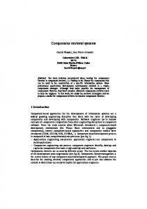
The MDA paradigm envisages the creation of a high-level model of the “problem” that the system under construction is intended to help solve, without concern for the fact that the system is a computer-based entity. In KobrA, the CIM is described by three different views (diagrams) representing the three core projections described above (see section 1.2.2). The Enterprise Concept Diagram represents the structural projection, the Enterprise Process Diagram represents the functional projection, and the Enterprise Workflow Diagram represents the behavioral projection. 1.3.1.1 Enterprise Concept Diagram The Enterprise Concept Diagram (ECD) represents the structural projection of the problem space and describes the basic concepts of concern in the problem domain (similar to the domain model in classic OOAD [10]; in other words it can be understood as a computation-independent domain model). As can be seen in figure 5 the ECD shows the Store as simply one of a community of actors and relevant object types (conceptual classes). The actors are marked with the stereotype and the object types with the stereotypes . 1.3.1.2 Enterprise Process Diagram The Enterprise Process Diagram (EPD) represents the functional projection of 10
package Context Realization[
Enterprise Concept Diagram ]
Custom er
* Receipt
Headquarters
*
Manager
* Product
1..*
*
Order *
Report
1..* *
* Cashier
*
*
1..* * *
Store
*
Stock
* Bank
* 1..* Supplier
StockManager
Fig. 5. Enterprise Concept Diagram of the Store
the problem space and describes the basic functions (processes) that occur in the problem domain and how they are related to one another. It is similar to the structural models applied in the structured development techniques that used to be popular in the 1970s and 1980s (e.g. [11]). As can be seen in figure 6, it groups the processes (functions) in the domain into a hierarchy. In the trading system case study we have chosen to view the predefined use cases as subprocesses of three major processes: the Store Management process, the Customer Interaction process and the Third Party Interaction process. The customer interaction group is decomposed into the processes UC1 – Process Sale and UC2 – Manage Express Checkout – each representing a use case. The store management group is decomposed into the process UC6 – Show Delivery Reports and the subgroups Inventory Management and Personnel Administration. Other groupings are imaginable but are not shown in the diagram since the modeling of the enterprise processes is restricted to those regarded as use cases. In KobrA, these are represented at the leaf nodes of the enterprise process tree. We added the node Personnel Administration to highlight the absence of some additional use cases describing the activities of staff management that are supported by the store system. Note the UC8 – Product Exchange (on low stock) Among Stores is a part of more than one parent group. This kind of situation is common in complex systems.
1.3.1.3 Enterprise Workflow Diagram The Enterprise Workflow Diagram (EWD) represents the behavioral projection of the problem space and describes the control and data flows that occur in the domain. It takes the form of a workflow-style diagram such as supported in BPMN [12] or Scheer [13], or activity diagrams in the UML. The EWD complements the EPD by describing the relationship between the processes and the 11
package Context Realization[
Enterprise Process Diagram ]
TradingSystem
Custom er Interaction
UC 1 - Process Sale
Store Managem ent
Third Party Interaction
UC 2 - Manage Express Checkout
Personnel Adm inistration
Inventory Managem ent
Inventory Monitoring
UC 6 - Show Delivery Reports
Goods Managem ent
UC 5 -Show Stock Reports
Purchase Goods
UC 3 - Order Products
UC 7 - Change Price
UC 8 - Product Exchange (on low stock) Am ong Stores
UC 4 - Receive Ordered Products
Fig. 6. Enterprise Process Diagram
UCs respectively. To enhance legibility, it can be split up into several subparts as illustrated in figure 7. The workflow of the Supplier is not complete since it does not have a direct bearing on the store. 1.3.2
Platform Independent Model
The Computation Independent Model describes the problem that needs to be solved at a high level of abstraction without regard for the fact that IT technology will be used to realize a solution. The “system”, if it appears at all, is simply viewed as one of the many actors involved in the domain. The next major level of abstraction in MDA is the Platform Independent Model which describes the IT solution without referring to the idiosyncrasies of a particular execution platform. This is the level of abstraction that KobrA primarily focuses on. In KobrA, the properties of the system and the various components making up the system are described in a platform independent way using UML views. However, in contrast with most other methods, KobrA treats every component separately and uniformly, and organizes the platform independent views of the components in a way that corresponds to, and highlights, the composition hierarchy. 1.3.2.1 Context Realization At the top of KobrA’s component modeling hierarchy is the context realization. This describes in detail how the system interacts with its environment (i.e. its 12
Manager
Store
show all products in stock
choose products to be ordered and enter ammout
select appropriate supplier and submit order
receive products show order ID
update stock
correct
Stock Manager
Application
order products start store application to order products
check correctness of delivery
Purchase Order
X
+
send delivery back
Purchase Order
Reclamation
Supplier
Shipping
receive order
ship order
...
roll in delivery
...
register reclamation
+
+
...
+
Fig. 7. Purchase Goods Enterprise Workflow Diagram
context) and what types the system manipulates. The term “realization” reflects the fact that the design of a system’s interaction with its environment constitutes a solution to the high-level problem defined in the CIM, and usually involves a redesign of existing practices. Also, as will be highlighted later, the context realization uses the same views as the realizations inside the system. In UML terminology, the context realization is a composite system, and is described using the standard “composite system” views advocated in KobrA. Structural View The structural view of the context realization describes the information and structural aspects of the environment of the system. It takes the form of a UML class diagram and shows the agents that the system interacts with, the types that the system shares with its environment (e.g. parameter types) and the operations that the various actors and the system expose to one another. The context realization explicitly focuses on those entities which will be implemented as part of the system. Therefore, the concept named Store in the ECD is renamed to TradingSystem to make it clear that we are no longer considering the real world notion of “store”, but are describing the entity to be developed as a computer based system. Figure 8 describes the structural model of the trading system based on the previously described enterprise environment, the use case have become responsibilities of the TradingSystem there. Note that in the structural view of the context realization only those components are included that occur in the abstract interaction models at this level. Roles and types in the CIM that do not have a direct bearing on the operation of the system are not included. Functional View The functional view shows the functional responsibilities assigned to the system 13
package ContextRealization 2[
Structural Model ]
Bank +validateCard() +debitCard()
TradingSystem
Manager
Receipt
*
StockManager
1..* Cashier
+cardPayment() +cashPayment() +changePrice() +enterAmount() +finishSale() +identifyItems() +listProducts() +listProductsRunningOutOfStock() +orderProducts() +rollInDelivery() +show DeliveryReport() +show StockReport() +startNew Sale()
1..*
Supplier
1..*
Order
1..*
Product
1..*
1..*
1..*
*
Custom er
Fig. 8. Context Realization Structural View showing the responsibilities of TradingSystem
and to the actors/components in the environment of the system, and shows how these make use of each others functionality by sending messages. It takes the form of a set of interaction diagrams – one for each use case to be supported by the system. interaction Receive Ordered Products [
Receive Ordered Products ]
: Supplier
: StockManager
: TradingSystem
1: delivery arrives
alt 2: roll in delivery(orderID) [if order correct]
[else]
3: send back order
Fig. 9. Context Realization Functional View – Receive Ordered Products Use Case
As illustrated in figure 9, by convention in the context realization the functional view is shown in the form of sequence diagrams. This reflects the tradition of using sequence diagrams (rather than other forms of interaction diagrams) for showing interactions with the system when viewed as a black-box. In further 14
refinement steps, when lower level components are modeled, communication diagrams are used instead. Behavioral View The behavioral view shows the workflows/algorithms that are used to realize the use cases that the system needs to support. It complements the functional view by showing the algorithms (i.e. control flows and data flows) used to invoke the operations involved in realizing the use case. It takes the form of a set of UML activity receiveOrderedProducts [ receiveOrderedProducts ] activity diagrams – one for each use case to be supported by the system. Figure 10 gives an example.
checkProducts
sendOrderBack [else]
[order correct] rollInDelivery
Fig. 10. Context Realization Behavioral View – Receive Ordered Products Use Case
1.3.2.2 TradingSystem Specification The focus of the context realization is the system’s relationship to its environment. As mentioned above, the context realization represents a “composite system” view of the community of actors which interact to realize the goals and/or business processes of concern. The system specification, in contrast, takes a “component” view of the system and provides a complete “context independent” description of the externally visible properties of the system. By “context independent” we mean that the external actors that invoke the operations of the system are only represented if their identity is essential to the functioning of the system. If the identity of users is not important, as is usually the case, they are not included in the specification. Structural View KobrA’s principles of locality and parsimony require that the specification of a component only contains those components and actors that are directly needed by the component. In other words, the specification of a component should only contain the other components and actors that are called by the component under consideration. The subject of the specification is identified by the stereotype in the structural view. Actors that are only callers from a component’s point of view are of minor importance, as these could be replaced by 15
any other actor calling the same functionality without losing any information. In the TradingSystem, the Manager is a good example of this since it only calls the TradingSystem. As illustrated in figure 11, the structural view of the TradingSystem specification contains the components which are acquired and the major entities that are necessary for the interaction/information exchange between the components. The structural view can be complemented by OCL constraints, e.g. invariants as shown in figure 11. package TradingSystem Specification[ Structual Model ]
TradingSystem
*
+validateCard +debitCard
+cardPayment +cashPayment +changePrice +enterAmount +finishSale +identifyItems +listProducts +listProductsRunningOutOfStock +orderProducts +rollInDelivery +show DeliveryReport +show StockReport +startNew Sale 1..*
Product 1..*
1..*
*
Supplier
Bank
1..*
-EAN -id -name -purchasePrice -salesPrice 1..*
inv: purchasePrice > 0
inv: salesPrice > 0
Order -id
Fig. 11. Trading System Specification Structural View
Note that at this stage of refinement no distinction is made between the product type added to the inventory and the product type sold in the real existing store, as defined in the description of CoCoME. Both represent the same real world object and refinements are not needed here because the attributes are of no interest at this stage. In general, components have two roles in a system – one role is as a container which encapsulates and provides an identity for a logically coherent group of components (i.e. a composite system in the UML) and the other role is as a contributor of its own functionality to the overall functionality of the system. Some components, however, may only fill one role or the other. Some components only serve to encapsulate a group of lower level components, and have no direct functionality of their own. Others only contribute functionality to the overall system and do not have any subcomponents. The latter represent the leaves of the composition hierarchy, since by definition they do not contain subcomponents, and the former, known as “virtual” components in KobrA 2.0, occupy higher position in the composition hierarchy and by definition cannot be leaves because they must have subcomponents. The term “virtual” emphasizes the contrast to physical components with their own functionality. The TradingSystem is an example of such a virtual component – that is, a component which has no direct functionality of its own, but simply serves as 16
logical container that acts as a facade for a composite system. In UML terminology, TradingSystem is an example of a component which has no “behavior” of its own, but delegates the responsibility for realizing its functionality to its subcomponents. The stereotype is used to indicate that a component is virtual. In addition, note that the structural view of the specification does not contain brackets after the operation names. The reason is that we regard the functionality of a component as a responsibility the component has been assigned rather than as an operation in normal sense. This is consistent with the virtual concept, as a virtual component cannot have normal operations of its own. Functional View The functional view of the TradingSystem specification describes the effects of each of its responsibilities. They are documented in the form of operation specifications whose general form is shown in the template in table 1. Name
name of the operation
Description identifies the purpose and provides a short informal description of the normal and exceptional executions Constraints properties that constrain the realization and implementation of the component Receives information passed to the operation by the invoker (analogous to the arguments of an operation in a programming language) Returns information returned to the invoker by the operation (analogous to the return value of an operation in a programming language) Sends messages sent to acquired component instances, can be events or operation invocations Reads identifies externally visible information that is read but not changed by the operation Changes lists externally visible information that is changed by the operation Rules rules governing the computation of the result Assumes weakest precondition on the externally visible properties of the component and on the inputs (see receives clause) that must be true for the component to guarantee the post-condition (result clause) Results strongest post-condition on the externally visible properties of the component and the returned information (returns clause) that becomes true after execution of the operation with true assumes clause
Table 1. Operation Specification Template
Each entry in this template needs only to be included in an operation specification if it carries useful information for that operation. Moreover, the information can be represented formally in OCL or in the semiformal style popularized by the Fusion method [14]. In general there is one operation specification for each responsibility, but for space reasons we only show the specification of the changePrice operation in table 2 below. This uses the semi-formal Fusion style combined with OCL constraints. Behavioral View The behavioral view shows the externally visible states of the component and the meaningful sequences of operation invocations. Since the trading system serves 17
Name
changePrice
Description This method changes the salesPrice of a product. productID : String – the identifier of the product Receives price : Real – the new salesPrice of the product success : Boolean – true, if the salesPrice is changed Returns – false, otherwise. The salesPrice of the product. Changes -- exactly one Product exists with the ID = productID pre: Product.select(id = productID).size() = 1 Assumes pre: price > 0 post: Product.select(id = productID).first().salesPrice = price Result
Table 2. TradingSystem Specification Functional View – changePrice Operation
multiple users simultaneously it has no externally visible states. Each operation can be invoked at any time. 1.3.2.3 TradingSystem Realization The realization of a component describes its design as if it were a “composite system” in the UML sense. The information in the specification structural view is still valid, but is augmented by the additional design information used to realize the component’s services – that is, by a description of how the properties exposed in the specification are supported in terms of internal algorithms and interactions with other components and data structures. Structural View Based on the original design of the system (see figure ??, the TradingSystem is composed of three types of subcomponents – Inventory, CashDesk, and Coordinator which coordinates interaction with the available CashDesk instances (see figure 12). From a UML perspective, the class diagram representing the realization structural projection can be regarded as a refinement of the class diagram representing the specification structural view. This means that all the information contained in the specification structural view is also present in the realization view, but additional design information has been added. An interesting issue in deciding the internal make up of the trading system is the usefulness of the CashDeskLine component used in the original solution (see figure ??). Although this does not appear in the use case diagram, the sequence diagram (see figure ??) provides a clear description of how the express checkout is triggered by a Coordinator within the CashDeskLine. The CashDeskLine itself is actually a virtual component of the kind discussed above since it essentially serves to encapsulate the set of CashDesk instances within the system, and provides no direct functionality of its own. However, since the TradingSystem is already a virtual component, and there is little to be gained from nesting virtual components directly within one another, we decided to omit CashDeskLine from our design. An interesting aspect of the decomposition of the TradingSystem into the three subcomponents Coordinator, CashDesk and Inventory, is that we can 18
package TradingSystem Realization[
Structual Model ]
Bank
Coordinator
+validateCard() +debitCard()
+registerSale()
TradingSystem
CashDesk 8
+cardPayment() +cashPayment() +enterAmount() +finishSale() +identifyItems() +startNew Sale() +triggerExpressCheckOut()
Inventory +getProductWithStockItem() +changePrice() +show StockReport() +listProductsRunningOutOfStock() +listProducts() +show DeliveryReport() +orderProducts() +updateInventory() +rollInDelivery()
1..* Cashier
*
Customer
* SalesProduct Product StockItem *
-EAN -id -name -purchasePrice -salesPrice
-amount -maxStock -minStock
1..* StockManager
inv: purchasePrice > 0
inv: salesPrice > 0
inv: maxStock > minStock 1..* Supplier
Order 1..*
-id
Fig. 12. TradingSystem Realization Structural View
now see a difference between the real world products added to the inventory and those passed through the cash desk, since those added to the inventory represent StockItems, with the additional information that the inventory should have a minimum or a maximum amount of this product. To stay as faithful as possible to the CoCoME we decided to model them as two separate classes – StockItem which represents products in the Inventory and SalesProduct which represents products associated with the CashDesk. To show that they are conceptually related they are both defined as specializations of Product. Functional View Each responsibility described in the specification of the TradingSystem component is refined and added to the realization of the component. In the case of a virtual component such as TradingSystem the responsibilities are divided into subresponsibilities and are distributed amongst the subcomponents. The functional view of an operation’s realization is captured in terms of interaction diagrams. These take the form of communication diagrams and clearly illustrate which additional components are used. Only those that are called from or created by the component under consideration have a representation in the structural model. Figure 13 shows the functional view of the realization of the rollInDelivery operation. Due to lack of space the other operations of TradingSystem are not shown here. 19
interaction rollInDelivery [
rollInDelivery ]
1: rollInDelivery(orderID)
: TradingSystem
2: rollInDelivery(orderID)
: Inventory
Fig. 13. TradingSystem Realization Functional View – rollInDelivery Operation
Behavioral View The behavioral view shows the algorithms used to realize the component’s operations in terms of activity diagrams – one for each operation. Again, for space reasons, we consider only one operation here, rollInDelivery (see figure 14). The small fork-like symbol in the activity indicates that it is further refined at the next level of (anchor notation). activity rollInDelivery [ decomposition rollInDelivery ]
rollInDelivery : rollInDelivery
Fig. 14. TradingSystem Realization Behavioral View – rollInDelivery Operation
1.3.2.4 CashDesk Specification A fundamental principle of the KobrA approach is that all components should be described in the same way regardless of their location in the composition hierarchy. As long as a component is sufficiently complex it can be further decomposed into additional subcomponents. Due to the shortage of space we concentrate on the CashDesk component in this section since the Inventory and the Coordinator are treated in the same manner. Structural View All components have a specification and a realization which are viewed from the same perspectives as before. Like the TradingSystem component, CashDesk is a virtual component which means its responsibilities are implemented by delegation to operations of its subcomponents. Figure 15 shows the structural view of the CashDesk component.
20
MagicDraw UML, 1-1 C:\Dokumente und Einstellungen\moni\Eigene Dateien\12.0_cocome_2007-07-2
package CashDesk Specification[
Structural Model ]
Bank +validateCard +debitCard Coordinator
+registerSale
Cashier
CashDesk +cardPayment +cashPayment +enterAmount +finishSale +identifyItems +startNew Sale +triggerExpressCheckout
Inventory
+getProductWithStockItem +updateInventory
* SalesProduct
Custom er
Fig. 15. CashDesk Specification Structural View
Functional View As before, the functional view of the components shows the effects of each operation in terms of declarative operation specifications. In table 3 we show the specification of the cardPayment responsibility.
Name
cardPayment
Description This method realizes the card payment. Constraints For the payment the connection to the bank has to be established. sum : Real – the sum to pay Receives success : Boolean – true, if the payment was successfull Returns – false, if the customer cannot pay via card. Bank:validateCard(cardInformation, pin) Bank::debitCard(transactionID) Sends The card of the customer is debited. Changes Bank::debitCard(transactionID) can only be called, if the card is valid. To validate the card the customer has to enter his PIN. The cardInformation is Rules read from the credit card of the customer. pre: sum > 0 Assumes The card of the customer is debited with sum. Result
Table 3. CashDesk Specification Functional View – cardPayment Operation
Behavioral View The behavioral view shows how the CashDesk component responds to external stimuli, and when the operations of the component may be sensibly executed. Figure 16 shows that there are two major operational states of the CashDesk, normalMode and expressMode. The latter is triggered from outside the CashDesk 21
under certain conditions. It further shows the operations which can be executed within the states and the events leading to the state transitions. 1.3.2.5 CashDesk Realization As usual, the realization of the CashDesk describes how the properties described in its specification (i.e its contract with other components) are realized in terms of internal algorithms and interactions with other components and data structures. Structural View Since the CashDesk is also a virtual component and therefore has no direct functionality of its own, none of the responsibilities of the component are shown in the structural view as shown in figure 17. This reinforces the idea that the component doesn’t have any operations of its own, but fulfills its responsibilities by delegation. Functional View Figure 18 shows how the cardPayment responsibility of CashDesk is realized. In addition to the components involved in the cashPayment, paying by credit card also involves the components CardReader and Bank. The Customer also has to enter his PIN into the CardReader. Behavioral View At the level of the CashDesk realization the responsibility identifyItems has to be refined into lower level activities. Figure 19 shows the algorithm used to realize identifyItems. Each SalesProduct is identified via the BarCodeScanner. If a SalesProduct is not recognized by the scanner it is possible either to add its identifier by hand (enterEANByHand) or to completely reject the Product. Inventory (not shown here) is also a virtual component whose functionality is delegated to its subcomponents. 1.3.2.6 CashDeskApplication Specification Since the components of CashDesk are still relatively complex they are further decomposed into subcomponents using the same basic process. Here we focus on the CashDeskApplication subcomponent which was given in the CoCoME. As usual, we first describe the CashDeskApplication’s specification level. However, in this case, the component is a concrete one with concrete operations of its own (see table 4). Structural View Figure 20 shows the structural view of the CashDeskApplication component. Functional View Table 4 shows the operation specification of the operation setPayMode, which is part of the functional model of the CashDeskApplication. The operation is 22
state m achine Cash Desk Statechart[
entry / setLightDisplay(black)
Ready
startNew Sale
finishSale
SaleFinished
enterItem
CollectItem s
enterItem
New Sale
Norm alMode
Cash Desk Statechart ]
[!expressModeTriggered]
BarPaym ent
[expressModeTriggered]
payCash payCash
payWithCard
disableExpressMode
OutputItem Error entry / outputError
disableExpressMode
itemNotRecognized
disableExpressMode
entry / setLightDisplay(green) disableExpressMode
Ready
startNew Sale
processSale
saleFinished
entry / registerSale
makePayment BarPaym ent
payCash
SaleFinished
ExpressMode
New Sale
enterItem
CollectItem s entry / int noItems = 1
OutputItem Error entry / outputError itemNotRecognized
enterItem [noItems < 8] / noItems++
23
processSale entry / registerSale
makePayment
processCardPayment
CardPaym ent
cardError OutputCardError entry / outputError
Fig. 16. CashDesk Specification Behavioral View
package CashDesk Realization[
Structural Model ]
CashBox +cardPayment() +cashPayment() +enterEANByHand() +finishSale() +getAmount() +openCashBox() +startNew Sale()
SalesProduct
Light Display
Bar Code Scanner
+sw itchExpressMode() +sw itchNormalMode()
CashDesk
+scanProduct()
Printer +finishSale() +startNew Sale()
CashDeskGUI +display() +startNew Sale()
CashDeskApplication
CardReader +readCard()
Cashier
+addProduct() +finishSale() +setCardInformation() +setPayMode() +startNew Sale()
Coordinator +registerSale()
Custom er Bank
Inventory
+validateCard() +debitCard()
+getProductWithStockItem() +updateInventory()
Fig. 17. CashDesk Realization Structural View
called when the customer wants to pay. He has the choice to pay via credit card or cash. His decision is sent to the CashDeskApplication via the mode parameter of the setPayMode operation. Depending on the mode, the CashDeskApplication communicates with the CardReader and the Bank or with the CashBox to complete the payment. At the end of the setPayMode method the Inventory is updated with the purchased Products.
Behavioral View The behavioral view of CashDeskApplication in figure 21 shows the different externally visible states of the component. This process of decomposition can be continued but due to the lack of space we do not show any further components here. Hopefully it should by now be clear how the KobrA approach is based on the hierarchical organization and description of components in the system. 24
interaction cardPayment_falsch[
cardPayment ]
: CashDesk
1: cardPayment
2: cardPayment() 3: setPaymode(CARD) : Cashier
: CashBox
: CashDeskApplication 7: transactionID:= validateCard(info, PIN)
5: pullCardRequest
4: info,PIN:= readCard()
: CardReader
8: [transactionID != null] debitCard(transactionID) 6: PIN:= askForPIN activity identifyItems [
identifyItems ] : Bank
: Custom er
Fig. 18. CashDesk Realization Functional View – cardPayment Operation scanProduct 15: processPayment
[else] [invalid id] : CashDesk
signalError
11: cashPayment()
9: setPayMode(CASH) enterEANByHand : CashBox
: CashDeskApplication
10: amount:=getCashAmount()
[id human-readable] 12: openCashBox()
16: amount:=getAmount
rejectItem
[else]
13: display(amount)
Fig. : Cashier
1.3.3
14: display(change)
19. CashDesk: CashDeskGUI Realization Behavioral View – identifyItems Operation
Platform Specific Model
The platform independent description of the CoCoME example developed in section 1.3.2 describes the system at a level of abstraction which is independent of specific platform idiosyncrasies. The models focus on elaborating the component structure of the system by describing how the larger components are composed of smaller components which in turn are composed of smaller components until a level of granularity is reached where further decomposition is unnecessary. Each component is described in the same way whatever its location in the composition hierarchy is. The next step in the MDA process is to develop one or more platform specific models in which one or more of these abstract (or logical) component representations are mapped into a more platform specific form, with the eventual goal of creating executable incarnations of the components. KobrA does not prescribe 25
package CashDeskApplication Specification[
Strucutral Model ]
Inventory +getProductWithStockItem +updateInventory Bank +validateCard +debitCard
CashDeskApplication
state m achine CashDeskApplication Specification[
CardReader
CashDeskGUI +display
CashDeskApplication Specification ]
+addProduct +finishSale +setCardInformation +setPaymode +startNew Sale
+readCard
CashBox +openCashBox +getAmount
Fig. 20. CashDeskApplication Specification Structural View Idle
finishSale finishSale
startNew Sale
finishSale
SaleInProgress
setPaymodeCash setPaymodeCard
SaleInProgressCardMode setCardInformation
setPaymodeCash
SaleInProgressCardInform ation setCardInformation
Fig. 21. CashDeskApplication Specification Behavioral View
how this is done or in what form the “platform specific” forms of components should be represented. This obviously varies in accordance with the nature of the platform. However, in order to illustrate what form the platform specific models of components might take, in this section we briefly show some examples. Figure ?? shows how the CashDeskLine component is implemented with the help of the components of a middleware based platform. As we explained above, we chose to omit CashDeskLine in our model, but instead we can show how CashDesk might be realized using a similar approach. This is illustrated in figure 22. Similarly, we can also show how specific instances of our overall architecture are deployed to specific nodes of the network. This is illustrated in figure 23.
1.4
Analysis
As explained in section 1.1, KobrA is intended to be a component-oriented way of performing system design using the UML. As with most uses of the UML for 26
MagicDraw UML, 1-1 C:\Dokumente und Einstellungen\moni\Eigene Dateien\12.0_cocome_2007-08-0
Name
setPayMode
Description Constraints Receives Returns
The customer wants to pay via card or cash. For card payment the network connection to the bank has to be established. mode:String – the paymode, could be ”CASH” or ”CARD” Boolean: true for success, false for failure e.g. when card payment returns a false value, the Cashier could try bar payment. Inventory::getProductWithStockItem(barcode) CardReader::readCard() – for card payment Bank:validateCard(cardInformation, pin) Bank::debitCard(transactionID) CashBox::getAmount() CashBox::openCashBox() – to open the CashBox CashDeskGUI::display() – to display the sum or the amount of change Inventory::updateInventory(shoppingCart) – to update the Inventory when the payment was successful Inventory::getProductWithStockItem(barcode) The Inventory is updated and in the case of card payment, the card of the customer is debited. The amount which the customer has to pay is the sum of the items in shopping cart plus some taxes. pre: CashBox.getAmount() > 0 The Inventory is updated. The card of the customer is debited with the amount of the shopping cart or the customer paid cash.
Sends
Reads Changes Rules Assumes Result
Table 4. CashDeskApplication Specification Functional View – setPayMode operation
design, therefore, the analyzing, checking and/or prediction of system properties is not the main focus of the modeling effort. The main value of the models is as an easy-to-read communication vehicle to facilitate discussions and joint understanding between members of the development team and between the development team and customers/users. The design models also serve as the starting point for the creation of the implementation. Although most UML tools today provide assistance in creating of implementations from models, no tool to date is able to provide a comprehensive mapping of all UML features to code. In mainstream development, therefore, some part of the implementation has to be written by hand. As a result, it is impossible to “prove” that an implementation so created will deliver the modeled properties because it is impossible to rule out human error. However, by creating a consistent and precise design of a system, which describes the properties of the system from multiple, focused viewpoints, the chances of creating a correct implementation with the desired properties is greatly increased. Since many UML diagrams are now inherently precise and unambiguous (because of the well defined semantics of the applied UML features) or can be made precise by the addition of OCL constraints, KobrA can be used to create precise and unambiguous descriptions of components and their designs. Moreover, because of the expressiveness of UML and OCL almost all kinds of system properties can be specified, especially if additional UML profiles are used, such as the Real Time [15] and Quality of Service profiles [16]. The essential prerequisite for a sound set of models is that they are internally well-formed and mutually consistent. At present we have no tool for checking this, although we have defined many well-formedness and consistency rules. In principle the usual well-formedness and consistency checking techniques used with other formalisms 27
package PSM[
cashDesk ]
CashDesk BarCodeScanner
CashDeskGUI
CashDeskApplication
Printer
LightDisplay
CashBox
EventBus
cashDeskChannel:EventChannel
extCom m Channel:EventChannel
Fig. 22. CashDesk Platform Specific Realization Structural View
can be used with KobrA models. As well as checking inter-model consistency, this includes 1. verification of state machines (e.g. reachability, dead-ends) on the specification behavioral views, 2. checks of pre and post condition compatibility and logical consistency on the specification functional views, 3. formal verification of algorithms on the realization functional and behavioral views.
1.5
Tools
As can be seen from the numerous diagrams, at its core KobrA is a view-based method which prescribes what content the different views of a component should contain and how they should be organized. Although there is no strict requirement to use tools when applying KobrA, developing all these views by hand and keeping them all consistent with one another is impractical without tool support. In this section we therefore give a brief overview of the tool support that we are developing at the Lehrstuhl f¨ ur Softwaretechnik at the University of Mannheim to address this need. The tool was designed with three main goals in mind – to provide a systematic and user friendly conceptual model and framework for defining and navigating around different views of a component and/or component based system – to provide a flexible infrastructure which allows consistency checking and view-generation tools to be easily and systematically defined and added – to use a unifying meta-model which allows all views to be generated automatically from a single underlying representation of a component 28
StoreServer Inventory::InventoryApplication
StoreClient Coordinator
Inventory::InventoryGUI
ProductContainer
EventBus
CashDeskPC LightDisplay
CashDesk::CashDeskGUI
BarCodeScanner
CashDesk:CashDeskApplication Printer
CashBox
CardReader
Bank
Fig. 23. TradingSystem Deployment Diagram
To make the complexity tractable for developers, the user interface is based on the metaphor of a multidimensional cube consisting of multiple cells. An example of a cell would be the structural view of the specification of the TradingSystem. A cell of the cube is determined by choosing a value for each dimension. The preconfigured dimensions for KobrA component development are “component”, “abstraction”, and “projection”. The component dimension specifies the (sub-) component which is being worked on at a particular point in time. The abstraction dimension determines the level of abstraction, with the default values being specification, realization, and implementation. The projection dimension identifies the structural, functional or behavioral viewpoint from which the component is being viewed. A cell can have one or more perspectives (e.g. a UML class diagram) on which the developer works with his favorite editor. The navigation, management and consistent maintenance of artifacts become increasingly difficult as their number increases. An ideal solution would be to have every editor working directly on a common model of the component and have changes synchronized with the model so that consistency among different views is ensured. This is the long term goal of the tool. As a pragmatic intermediate approach, multiple formats are supported and are synchronized by specially written “consistency checking” plugins. The environment is easily extendable, so that new editors or consistency checkers can be added at any time. It is possible to add an element to an existing dimension or to add a whole new dimension. For example, to support versioning, one could add a version 29
dimension with each dimension element representing different versions of the component. In summary, our tool serves as a framework for integrating professional CASE tools as well as self-made editors and offers a unified navigation paradigm and a single underlying metamodel. Artifacts from the employed tools, such as UML diagrams from MagicDraw, can of course be used outside our tool at any time.
1.6
Summary
In this chapter we have presented the CoCoME example as it might be modeled using the KobrA approach. The underlying nature of the components and system architecture is much the same as in the other approaches. What differs is KobrA’s way of visualizing and presenting components and composite systems. As mentioned at the beginning, KobrA encourages a uniform representation of components regardless of their granularity or their location in the composition hierarchy. This means that the same views and principles are used to model smaller components near the leaf of the tree (e.g. CashDeskApplication) as are used to model larger component at the root of the tree (e.g. TradingSystem). In addition, KobrA requires all components in the tree to be described at the same level of abstraction (i.e. at the same level of platform independence). Thus, CashDeskApplication has the same level of platform independence as TradingSystem. Changes in platform specificity are clearly visible and are separated out into a different set of models (i.e. one or more platform specific models). An important aspect of all software specification approaches is the ability to define extra functional properties and requirements. In KobrA the difference between extra functional requirements and extra functional properties is that the former are associated with specifications and the latter with realizations. An extra functional “statement” in a specification is a promise that the component makes to its clients. It is part of its contract with them and thus is something that the builder of the component must fulfill – it is a requirement. In contrast, an extra functional “statement” in the realization of a component is a description of some fact that is true about the chosen design – it is a property. Extra functional requirements and properties can be added to KobrA models in one of two ways. They can either be added to the existing views in the form of constraints or annotations or they can be defined in an additional “extra functional properties/requirements” view, or both. At the specification level, extra functional requirements that apply to a single method can easily be added to the operation specification of that method by adding specialized clauses (rows). Extra functional requirements that span methods (i.e. invariants) are best defined in a separate view, however. At first sight, KobrA’s strategy of creating “localized” views of each component may seem to involve a great deal more redundancy and verbosity than is necessary. To a certain extent this is true. However, provided that suitable tool support is available, we believe the advantages of separating concerns, treating all components uniformly, and fully elaborating their properties from a number 30
of orthogonal viewpoints, greatly outweigh the costs. They not only simplify and clarify the initial development process, they make the resulting components and component-based systems much more maintainable and reusable.
1.7
Acknowledgements
The presented work was partially supported by the ECOMODIS project funded by the “F¨ orderprogramm Informationstechnik Baden-W¨ urttemberg (BW-FIT)” (http://www.ecomodis.de).
1. Fraunhofer Institute for Experimental Software Engineering: The MARMOT Project - Component-based Development of Embedded Systems. http://www.marmot-project.de/de/home/index.html (2003) 2. Brenner, D., Atkinson, C., Paech, B., Malaka, R., Merdes, M., Suliman, D.: Reducing Verification Effort in Component-Based Software Engineering through Built-In Testing. In: Proceedings of the International IEEE Enterprise Computing Conference (EDOC2006) 16th-20th October, Hong Kong . (2006) 3. Atkinson, C., Bayer, J., Bunse, C., Kamsties, E., Laitenberger, O., Laqua, R., Muthig, D., Paech, B., W¨ ust, J., Zettel, J.: Component-Based Product Line Engineering with UML. 1st edn. Addison Wesley, Reading, Massachusetts, USA (2001) 4. OMG: UML 2.0 Superstructure Specification. http://www.omg.org/docs/ptc/0308-02.pdf (2003) 5. Warmer, J., Kleppe, A.: The Object Constraint Language: Precise Modeling with UML. Addison-Wesley Longman Publishing Co., Inc. Boston, MA, USA (1998) 6. OMG: MDA Guide Version 1.0.1. http://www.omg.org/docs/omg/03-06-01.pdf (2003) 7. Ambler, S.W.: Agile Modeling. http://www.agilemodeling.com (2006) 8. Clements, P., Northrop, L.: Software Product Lines. Addison-Wesley Boston (2002) 9. Bayer, J., Flege, O., Knauber, P., Laqua, R., Muthig, D., Schmid, K., Widen, T., Debaud, J.M.: PuLSE. A Methodology to Develop Software Product Lines. In: Proceedings of the Symposium on Software Reuse (SSR ’99). (1999) 10. Larman, C.: Applying UML and Patterns: An Introduction to Object-Oriented Analysis and Design. 3 edn. Prentice Hall (2005) 11. Coad, P., Mayfield, M.: Coad, Yourdon, and Nicola: OOA, OOD, & OOP. WileyQED Publishing, Somerset, NJ, USA (1994) 12. OMG: Business Process Modeling Notation Specification - version 1.0. http://www.bpmn.org/Documents/OMG Final Adopted BPMN 1-0 Spec 06-0201.pdf (2006) 13. Scheer, A.W.: ARIS - Modellierungsmethoden, Metamodelle, Anwendungen. Springer Verlag (2001) 14. Coleman, D., Arnold, P., Bodoff, S., Dollin, C., Gilchrist, H., Hayes, F., Jeremaes, P.: Object-Oriented Development. The Fusion Method. Prentice Hall (1994) 15. OMG: UML Profile for Schedulability, Performance and Time. http://www.omg.org/cgi-bin/doc?formal/2005-01-02 (2005) 16. OMG: UML Profile for Modeling QoS and Fault Tolerance Characteristics and Mechanisms. http://www.omg.org/cgi-bin/doc?formal/06-05-02 (2006)
31