Architecture of FE with super-scalar and pipeline design. CPU. Link Interfaces ...... ACM SIGCOMM'97,. Palais des Festivals, Cannes, France, pp. 3-14.
A Fast IP Routing Lookup Scheme for Gigabit Switching Routers Nen-Fu Huang, Shi-Ming Zhao, Jen-Yi Pan, and Chi-An Su Department of Computer Science, National Tsing Hua University Hsin-Chu, Taiwan, 30043, R.O.C. E-mail: {nfhuang, smzhao, dr844301, casu}@cs.nthu.edu.tw Abstract-One of the key design issues for the new generation IP routers is the route lookup mechanism. For each incoming IP packet, the IP routing requires to perform a longest prefix matching on the address lookup in order to determine the packet’s next hop. This paper presents a fast route lookup mechanism that only needs tiny SRAM and can be implemented in a pipelined skill in hardware. Based on the proposed scheme, the forwarding table is tiny enough to fit in SRAM with very low cost. For example, a large routing table with 40,000 routing entries can be compacted to a forwarding table of 450-470 Kbytes. In the worst case, the number of memory accesses for a lookup is three. When implemented in a pipeline skill in hardware, the proposed mechanism can achieve one routing lookup every memory access. With current 10ns SRAM, this mechanism furnishes approximately 100 million routing lookups per second. This is much faster than any current commercially available routing lookup schemes.
I. INTRODUCTION Due to the advent of the World Wide Web (WWW), the network traffic in the Internet is doubling every few months. The bandwidth hungry applications, such as Video-ondemand, Distance learning, Digital libraries, are expected to give traffic another major boost. In order to continue to furnish good QoS service, three key design issues on the next generation IP routers are: link speeds, router throughput, and packet forwarding rates. The first two issues are currently readily available. For example, fiber-optic cables can provide faster link speeds, and new IP switching technology (Layer-3 switching or multi-layer switching) can be used to transmit packets from the input interface of a router to the corresponding output interface at gigabit rates. This paper deals with the third design issue, packet forwarding, for which current mechanisms perform poorly as link speeds increase. Although the MAC address lookup scheme has been achieved at 100 Mbps (Fast Ethernet) for the Bridges and Layer-2 Switches in the past few years, it is based on the exact matching on the destination (MAC) address. For the Internet routers [1], what we need is to perform the longest prefix matching between a destination IP address and the routing table instead of the exact matching. This also implies that the famous schemes for exact matching, such as perfect matching and standard Content Addressable Memories (CAMs) cannot directly be employed for IP address lookups [7]. Since the number of end users as well as the amount of routing information on the Internet grows exponentially, the concept of prefix matching was introduced to reduce routing table entries in the early 1990s. Basically, the IP addresses space is divided into classes A, B, and C and sites are allowed
to have 24, 16, and 8 bits for addressing respectively. Nevertheless, this partition is inflexible and may waste of the address space, especially the class B addresses. In order to use this crucial resource, bundles of class C networks were furnished instead of class B addresses. This of course introduces the growth of the routing table entries. On the other side, the deployment of Classless Inter-Domain Routing (CIDR) scheme allows for arbitrary aggregation of networks to reduce the routing table entries [9]. In the way of CIDR, each IP route is identified by a pair, where the prefix length is in the range between 0 and 32 bits (0 stands for default route). When an IP packet is received, the IP router computes which of the prefixes in its forwarding database has the longest match when compared to the destination IP address in the packet. The packet is then forwarded to the output link associated with that prefix. For example, a forwarding database may have the entries , , and . An IP address 11.2.158.8 has longest prefix matching with the first entry. On the other hand, an IP address 11.2.96.168 has longest prefix matching with the last entry. Recently, several fast routing lookup mechanisms have been proposed [3], [4], [5], [6], [7], [8], [12], [13]. For example, a novel forwarding table structure is designed for quick routing lookups by Degermark, Brodnik, Carlsson, and Pink [3]. The forwarding tables are very small such that a large routing table with 40,000 entries can be compacted to a forwarding table of 150-160 Kbytes. This is a software-based solution. If in hardware implementation, the minimum and maximum number of memory accesses for a lookup is 2 and 9, respectively. Gupta, Lin, and McKeown presented fast routing lookup schemes based on the huge DRAM [5]. The maximum number of memory accesses for a lookup is 2 with a forwarding table of 33Mbytes. By adding an intermediate length table, the forwarding table can be reduced to 9 Mbytes, but the maximum number of memory accesses for a lookup is increased to 3. When implemented in a pipelined fashion in hardware, the proposed schemes can achieve one route lookup every memory. This furnishes about 20 million lookups per second. Waldvogel, Varghese, Turner, and Plattner proposed a lookup scheme based on the binary search mechanism [13]. This scheme scales very well as address and routing table sizes increase. It requires a worst case time of log2(address bits) hash lookups. Thus, 5 hash lookups are needed for IPv4 and 7 for IPv6 (128-bit) [2]. This software based binary search work is further improved by employing the cache structure and using the multiway and multicolumn search [6]. For a database of N prefixes with address length W, the native binary search scheme takes O(W*logN) searches. This improved schemes takes only
0-7803-5420-6/99/$10.00 (c) 1999 IEEE
O(W+logN) searches. These software based binary search schemes are not easy to be implemented in hardware. This paper presents a fast longest prefix matching mechanism for IP switching routers that only needs tiny SRAM and can be implemented in a pipelined skill in hardware. Based on the proposed scheme, the forwarding database is tiny enough to fit in SRAM with very low cost. For example, a large routing table with 40,000 routing entries can be compacted to a forwarding table of 450-470 Kbytes with the cost less of US$30. Most of the address lookups can be done by a memory access. In the worst case, the number of memory accesses for a lookup is three. When implemented in a pipeline skill in hardware, the proposed mechanism can achieve one routing lookup every memory access. With current 10ns SRAM, this mechanism furnishes approximately 100 million routing lookups per second. This is much faster than any current commercially available routing lookup schemes.
number) where the packet should be forwarded. The MAC address substitution module then substitutes the source MAC address and the destination MAC address of the packet before it is forwarded into the interface port. The source MAC address is replaced by that of the output interface, and the destination MAC address is replaced by that of the immediate next hop (a router or the destination host). The bottleneck of the forwarding engine is the route lookup and we will focus on the design and hardware implementation of fast lookup scheme. CPU
Forwarding Engine
Switching Fabric
The rest of the paper is organized as follows. The architecture of the Multi-gigabit switching router and the forwarding engine are introduced in Section 2. The proposed longest prefix matching scheme is presented in Section 3. The hardware implementation and the performance analysis of the proposed scheme are described in Section 4 and Section 5, respectively. Finally, a conclusion remark is given in Section 6.
.............. Link Interfaces
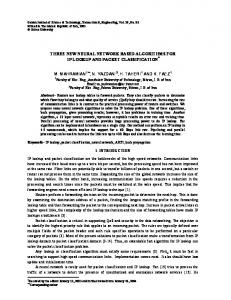
Fig. 1. Architecture of Gigabit IP switching router.
II. GIGABIT IP SWITCHING ROUTER ARCHITECTURE
The architecture of the forwarding engine (FE) is shown in Fig. 2. For an incoming IP packet, the route lookup process (based on the destination IP address of the packet), header verification, and header update are initiated simultaneously. If the IP header is not correct, the packet is dropped and the lookup is terminated. Otherwise, the header is updated into the packet header (TTL decrement and checksum update) and the route lookup module will provide the next hop (port
IPS
Bottleneck of Forwarding Engine
Route Lookup
WBE TTL Decrement and Checksum Update
Next Hop
32 Bits Internal Data Bus
The CPU module executes the routing protocols, such as RIP and OSPF, and needs a dynamic routing table for fast updates and fast generation of forwarding databases. On the other hand, it is better to optimize the forwarding database to furnish fast lookups. This also implies that the forwarding databases need not be dynamic.
Header Verification
32 Bits External Data Bus
The architecture of the Gigabit IP switching router is schematically shown in Fig. 1, where a number of link interfaces, a CPU module, and a forwarding engine are interconnected with a switching fabric. The forwarding engine employs a forwarding database, a local version of the routing table, downloaded from the CPU module to make the routing decision. Although routing updates may occur frequently, it is not necessary to download a new forwarding database for each routing update. This is because the routing protocols, such as RIP and OSPF, need time in the order of minutes to converge, and the forwarding tables can grow a little stale and need only be updated once per few seconds.
SBS MAC Address Substitution
Fig. 2. Architecture of FE with super-scalar and pipeline design.
0-7803-5420-6/99/$10.00 (c) 1999 IEEE
III. IP ROUTING LOOKUP SCHEMES The most straightforward lookup scheme is to have a forwarding database in which an entry is designed for each 32-bit IP address as shown in Fig. 3. This design needs only one memory access for IP address lookup but the size of forwarding database (next hop array) is too huge (232 = 4 GB) [5]. To reduce the size of forwarding database, the skill of indirect lookup shown in Fig. 4 can be employed [5]. Each IP address is partitioned into two parts: segment (16-bit) and offset (16-bit). The segmentation table is with the size of 64K entries (216) and each entry (32-bit) records either the next hop (port number, value < 256) of the routing or a pointer (value > 255) points to the associated Next Hop Array (NHA). Each NHA consists of 64K entries (216) and each entry (8-bit) records the next hop (port number) of the destination IP address. Thus, for a destination IP address a.b.x.y, the a.b is used as the index of the Segmentation Table and the x.y is employed as that of the associated NHA, if necessary. Thus, for a segment a.b, if the length of the longest prefix belongs to this segment is less than or equal to 16 (the segment length), then the corresponding entries of the Segmentation Table store the output port directly, and the associated NHA is not necessary. On the other hand, if the length of the longest prefix belongs to this segment is greater than 16, then an associated 64KB NHA is required. In this design, the maximum number of memory accesses for an IP address lookup is two. In [5], the segment length is of 24-bit and therefore a 16 Mbytes segmentation table is required. Although the indirect lookup scheme furnishes fast lookup (up to 2 memory access), it does not consider the distribution of the prefixes belongs to a segment. A 64KB NHA is required as long as the length of the longest prefix belongs to this segment is greater than 16. We now show our idea that by considering the distribution of the prefixes within a segment, we can further reduce the size of the associated NHA as shown in Fig. 5. Again, the IP address is still partitioned into segment (16-bit) and offset (≤ 16-bit). The segment is also 16-bit and the Segmentation table is with the size of 64K entries, each one (32-bit) is divided into two fields: pointer/next hop (28-bit) and offset length (4-bit). The first field records either the next hop (port number, value < 256) of the routing or a pointer (value > 255) points to the associated NHA. The second field indicates the length of the offset (k bits, 0 < k ≤ 16). For offset of k-bit length, the associated NHA is with the size of 2k entries. Remember that for the indirect lookup mechanism [5], the offset is always of length 16. Now, for each segment, the offset length indicates how many entries are needed in the associated NHA. This depends on the prefixes of the segment. Thus, for segment a.b, assume there are m prefixes and the longest one is of length 32 ≥ l > 16, then the offset length k for this segment is l-16. This also means that for a destination IP address a.b.x.y, the a.b is used as the index of the Segmentation Table and the left most k bits of x.y (from 16-th bit to (16+k-1)-th bit) is employed as that of the associated NHA, if necessary.
Actually, it depends on the set of prefixes of the segment as well as the length of each prefix. We now describe the mechanism to construct the NHA of a segment. Let li and hi denote the length and the next hop (output port) of a route prefix pi , respectively. Let oi = li – 16 and k = max{ oi | pi ∈ P } ( NHA is of size 2k ). Let P = {p0, p1, …, pm-1} be the set of sorted prefixes of a segment. Thus, for any pair of prefixes pi and pj, i < j if and only if li ≤ lj . For each prefix pi in P, let S i0 and Ei0 denote the data structure of the start point and end point of pi, respectively, that should be forwarded to hi. Without loss of generality, let ma( S i0 ) and ma( Ei0 ) stand for
S i0
the memory address of
Ei0
and
0 i
in the NHA,
0 i
respectively. Also let op( S ) and op( E ) stand for the output port of destination addresses of start point and end point, respectively. Assume pi = a.b.x.y. Let x0,x1,x2,…,x15 denote the binary form of x.y, s0,s1,s2,…,sk-1 denote the start point mask, where sj = 1, j < oi, and sj = 0, j ≥ oi., and e0,e1,e2,…,ek-1 denote the end point mask, where ej = 0, j < oi, and ej = 1, j ≥ oi., Then we have ma( S i0 ) = (x0,x1,x2,…,xk-1 AND s0,s1,s2,…,sk) and ma( Ei0 ) = (x0,x1,x2,…,xk-1 OR e0,e1,e2,…,ek-1). For example, assume pi = a.b.58.0, li = 26, and k = 12 (the longest prefix in this segment is of length 28). Then the binary form of 58.0 (k-bit) = 001110100000, s0,s1,s2,…,sk-1 = 111111111100, and e0,e1,e2,…,ek-1 = 000000000011. We have ma( S i0 ) = 001110100000 = 928 and ma( Ei0 ) = 001110100011 = 931. This also means that NHAj = hi, ma( S i0 ) ≤ j ≤ ma( Ei0 ). 1
32 Bits IPv4 Address Directly Spread for Exactly Matching
.............. Next Hop Array (4 GB) Fig. 3. Direct lookup mechanism.
IPv4 Address
Next Hop
16 Bits Segment
16 Bits Offset
Value < 256 ==> Next Hop (Without NHA) Value > 255 ==> Pointer Format Pointer/Next Hop 32 Bits
Segment
Point to Next Hop Array Segmentation Table (64K Entries)
....
Offset
Offset
Offset
......
Offset
Offset
........
........
........
........
........
64 KB Next Hop Array
64 KB Next Hop Array
64 KB Next Hop Array
64 KB Next Hop Array
64 KB Next Hop Array
The key point of this design is the construction of the NHA. 0-7803-5420-6/99/$10.00 (c) 1999 IEEE
Fig. 4. Indirect lookup mechanism.
k Bits Offset(k)
IPv4 Address
Next Hop
shown in Fig. 6(a). The corresponding constructed NHA is given in Fig. 6(b).
16-k Bits Remainder Bits
16 Bits Segment
Value < 256 ==> Next Hop (Without NHA) Value > 255 ==> Pointer
Now, let us consider another example where we have three prefixes on a segment: p0 = 11.1/16/1, p1 = 11.1.58/20/2, and p2 = 11.1.168/24/3. Since the longest prefix is of length 24, the offset length k equals to 24-16 = 8 (record as 0111 in the offset length field). Then the NHA for this segment is of size 28 = 256 entries. Moreover, we have ma( S 00 ) = 00000000 = 0,
Format Pointer/Next Hop 28 Bits
Segment
Point to Next Hop Array Segmentation Table (64K Entries)
4 Bits to indicate Offset length - 1
....
ma( E 00 ) = 11111111 = 255, ma( S10 ) = 00110000 = 48, ¯¯¯¯¯¯
Offset(k 0)
Offset(k 1)
Offset(k 3)
........
........
........
........
........
2k Bytes Next Hop Array
2k Bytes Next Hop Array
2k Bytes Next Hop Array
2k Bytes Next Hop Array
2k Bytes Next Hop Array
0
1
3
Offset(k i)
Offset(k i+2)
i
ma( E10 ) = 00111111 = 63, ma( S 20 ) = 10101000 = 168,
i+2
Fig. 5. Indirect lookup mechanism with variable offset length.
We note that for each prefix pi in P, we can find a pair of S and Ei0 . The memory addresses between ma( S i0 ) and 0 i
ma( Ei0 ) can be depicted as an interval [ma( S i0 ), ma( Ei0 )], and the set P of prefixes can be presented as a set of intervals. If all the intervals are not overlapping to each other, then we can construct the NHA directly by setting NHAj = hi, ma( S i0 )≤ j ≤ ma( Ei0 ). However, in most cases, this may not be true. An overlap stands for that for a destination IP address, we have more than one matching. But remember what we are looking for is the longest matching. Thus, if a memory address j belongs to a set P’ of intervals simultaneously, then we should set NHAj = hi , where pi is the longest prefix of P’. For example, assume each route prefix is presented by prefix/prefix length/next hop (output port). Then the set P of six sorted prefixes {192.168/16/1, 192.168.58/18/2, 192.168.92/24/1, 192.168.58.32/26/3, 192.168.255.240/28/5, 192.168.58.36/32/8} can be presented as the six intervals
ma( E 20 ) = 10101000 = 168. Therefore, NHA0~NHA47 = 1, NHA48 ~NHA63 = 2, NHA64~NHA167 = 1, NHA168 = 3, and NHA169~NHA255 = 1. For destination IP address 11.1.8.4, the offset is 8, and the output port can be found in NHA8 = 1. For destination IP address 11.1.168.4, the offset is 168, and the output port can be found in NHA168 = 3. Consider another extreme case where we have two sorted prefixes for a segment: p0 = 11.7/16/1 and p1 = 11.7.12.10/32/2. Since the longest prefix is of length 32, the offset length k equals to 32-16 = 16 (record as 1111 in the offset length field). Then the NHA for prefix 11.7 has 216 = 64K entries. In this case, we have ma( S 00 ) = 0000000000000000 = 0, ma( E 00 ) = 1111111111111111 = 65535, ma( S10 ) = ma( E10 ) = 0000110000001010 = 3082. Thus, we have NHA0~NHA3081 = 1, NHA3082 = 2, and NHA3083~NHN65535 = 1. For destination IP address 11.7.12.10, the offset is 3082, and the output port can be found in NHA3082 = 2. For destination IP address 11.7.x.y, 0 ≤ x,y ≤ 255, except 11.7.12.10, the offset q is (x×256+y), and the output port can be found in NHAq = 1.
192.168.58.36/32/8 p5 192.168.255.240/28/5 p4 192.168.58.32/26/3 p3 192.168.92/24/1 p2 p1
192.168.58/18/2 192.168/16/1
p0
S 30 S 50 E30E10 E50
S 00 S10
E20
S 20
ma(S00 ) = 0, ma(S10 ) = 0, ma(S20 ) = 23552, ma(S30 ) = 14848, ma(S40 ) = 65520, ma(S50 ) = 14884,
S 40 E00 E40
ma(E 00 ) = 65535 ma(E10 ) = 16383 ma(E 20 ) = 23807 ma(E 30 ) = 14911 ma(E 40 ) = 65535 ma(E 50 ) = 14884
(a) Interval presentation of P
2 ±
......
3
...
8 3
14848 14884
...
2
Next Hop Array 1
14912
...
16384
......
1
23552
...
1
23808
14885
(b) Constructed NHA Fig. 6. NHA construction example.
0-7803-5420-6/99/$10.00 (c) 1999 IEEE
......
5
65520
..
5
65535
The formal algorithm for constructing the NHA of a segment is given as follows. Algorithm NHA-Construction Input: The set of route prefixes of a segment; Output: The corresponding NHA of this segment. Step 1. Let li and hi be the length and output port of a route prefix pi , respectively. Step 2. Let P = {p0,p1,…,pm-1} be the set of sorted prefixes of a segment. Thus, for any pair of prefixes pi and pj, i < j if and only if li ≤ lj. Step 3. Let k = lm-1 -16 /* The size of NHA is 2k */ Step 4. For each prefix pi in P, calculate S i0 and Ei0 . Step 5. For i = 0 to m-1 do NHAj = hi , ma( S i0 ) ≤ j ≤ ma( Ei0 ); Step 6. Stop
In the worst case, the number of memory accesses for an IP address lookup is still two for this design, but the total amount of memory required is reduced significantly. The forwarding database structure (NHAs) shown in Fig. 5 can be further improved by employing the concept of compression. Thus, for each segment with offset length k > 3, the associated NHA can be replaced by a Code Word Array (CWA) and a compressed NHA (CNHA). To construct the CWA, we employ the technique of compression bit map (CBM), one bit for each entry in the original NHA. The compression rule is as follows. Let ai denote the value (port number) of the i-th entry of the NHA, bi stand for the corresponding bit in the CBM, and cj denote the value (port number) of the j-th entry of the CNHA. Initially, c0 = a0, b0 = 1, and j = 1. Then scan the NHA from left to right. If ai+1 = ai, then bi+1 = 0, else bi+1 = 1, cj = ai+1, and j = j+1. For example, the NHA shown in Fig. 7(a) can be compressed into the corresponding CBM and CNHA as shown in Fig. 7(b).
Actually, the CBM and CNHA of a segment can be constructed directly without constructing the NHA first. The algorithm to construct the CBM and CNHA directly from the given prefixes of a segment is depicted as follows. Before starting, we need to note that for any two distinct prefixes in a segment, either one is completely contained in the other, or the two distinct prefixes have no entries overlapping with each other [5]. Algorithm CBM/CNHA-Construction Input: The set P = {p0,p1,…,pm-1} of sorted route prefixes of a segment and L = { S 00 , E00 , S10 , E10 , …,
S m0 −1 , Em0 −1 }. Output: CBM and CNHA. Step 1. Sort L by memory address in the segment. For identical memory addresses, keep their order the same in L. Step 2. Let A = φ and stack C = φ. Step 3. Process the elements in L from left to right and for each element do Begin If the selected element is a start point S i0 then Push S i0 in C. Append S i0 in A. Else /* It is an end point Ei0 */ Begin Remove top element from stack C. If the top of stack C is S kj then Begin Append S kj +1 in A, where op( S kj +1 ) = op( S kj ),
ma( S kj +1 ) = ma( Ei0 )+1. Replace the top of stack C by S kj +1 . End Else /* Stack C is φ */ Do nothing. End End Step 4. Compact A such that for consecutive elements S kj
Next Hop Array 2 2 2 2 2 2 2 2 8 8 8 8 8 8 8 8 8 8 8 8 8 8 8 8 7 7 7 7 6 6 6 6
.........
2 2 2 2
(a) An NHA example
and S pq , remove S kj from A if ma( S kj ) = ma( S pq ), remove
S pq from A if op( S kj ) = op( S pq ).
Step 5. Remove each element S kj from A whose ma( S kj ) > Next Hop Array 2 2 2 2 2 2 2 2 8 8 8 8 8 8 8 8 8 8 8 8 8 8 8 8 7 7 7 7 6 6 6 6
.........
2 2 2 2
Compression Bit Map 1 0 0 0 0 0 0 0 1 0 0 0 0 0 0 0 0 0 0 0 0 0 0 0 1 0 0 0 1 0 0 0
.........
1 0 0 0
Compressed Next Hop Array 2 8 7 6 2
...........
(b) The corresponding CNHA and CBM
ma( E00 ); Step 6. For i = 0 to | A| - 1 do /* | A| is the number of elements in A */ Begin Let S kj be the i-th element in A ; CBMp = 1; where p = ma( S kj );
Fig. 7. NHA compression example.
CNHAi = op( S kj ) End Step 7. Stop 0-7803-5420-6/99/$10.00 (c) 1999 IEEE
The time complexity of the proposed algorithm is O(nlogn), where n is the number of prefixes in a segment. Since this algorithm constructs the CBMs and CNHAs directly from the given prefixes, the forwarding table can be built in a very short time. The CBM should be encoded as a sequence of code words (Code Words Array, CWA) as follows. Each code word consists of a map (16-bit) and a base (16-bit). The CBM is treated as a bit-stream and been partitioned into a sequence of 16-bit maps. Then these maps are put into the code words, one for each code word, sequentially. The base of each code word equals to the number of 1’s accumulated in the maps of previous code words. For example, the CBM shown in Fig. 7(b) is encoded as the code words depicted in Fig. 8. The maps of the first two code words are 1000000010000000 and 0000000010001000, respectively. For the first code word, the base has a value of zero. For the second code word, since the number of 1’s accumulated in the maps of previous code words is two, we have a base value of two. The base is used to indicate the start entry of the associated CNHA. Thus, for an offset value q, the output port can be computed as follows. Let cws = maps + bases be the code word contains this offset, where s = (q DIV 16). Let w = (q MOD 16) denote the corresponding bit of q in maps and |w| stand for the number of accumulated 1’s from the 0th bit to the w-th bit of maps. Then the output port of an offset value q is calculated as
opq = CHNAt, where t = bases + |w|-1. For example, consider the case shown in Fig. 7 and 8 again. For offset q = 8, we have s = 0, w = 8, and |w| = 2, then t = (base0+|w|-1) = 0+2-1 = 1 and the corresponding output port is CNHA1 = port 8. For offset value q = 25, we have s = 1, w = 9, and |w| = 1, then t = (base1+|w|-1) = 2+1-1 = 2 and the corresponding output port is CNHA2 = port 7. To update the forwarding table, we can either rebuild a new one in a short time or through special hardware design, such as dual-port memory or dual-memory banks. IV. HARDWARE IMPLEMENTATION The high-level hardware implementation of the proposed lookup scheme is shown in Fig. 9. First of all, the first 16 bits (bits 0~15) of an incoming IP address are used as an index of the Segment Table (64K entries, each with a length of 24 bits). The corresponding entry of the Segment Table records either the next hop (the value of left 20 bits < 256) of this
Code Word 16 Bits 16 Bits 1000000010000000 0 Map Base
Code Word Array
0000000010001000
destination IP address, or a pointer (20-bit), points to the starting address of the CWA, and an offset length k (4-bit). For each segment, if the offset length k > 3, then we need to decode the CNHA by searching the CWA (with 2k-4 entries) and finding the associated code word. From this code word, we have the map and base. Since the CNHA is placed immediately follows the CWA, the starting address of CNHA equals to pointer + 2k-4×4 – 1. An adder is designed here to add this with base and |w|. If k ≤ 3, then the k bits, starting from the 16-th bit of the destination IP address, are used as the index of the NHA (with 2k entries) to find the output port. The value of |w| can be computed by a parallel adder. For example, assume for a segment with offset length k = 8 and we have a destination IP address a.b.158.y with offset of 158. Then we should look at the s-th code word, where s = 158 DIV 16 = 9. Assume the map of this code word is 1000100011000100, then the bit position for this offset is 158 MOD 16 = 14. Let Bi j denote the bit stream from the j-th bit to i-th bit of an IP address and V ( Bi j ) stand for the value of
bit stream Bi j . To compute the value of |w|, we can first mask the right 16- V ( Bkk++1512 ) -1 bits of the code word into zero and then calculate the number of 1’s in this masked code word by the parallel adder in constant time. For the current ASIC technology, this can be done in 8 ns. We note that the width of the code word is 32-bit and is identical to that of the data bus. This means we only need a memory access to obtain a code word in the CWA. For a destination IP address a.b.x.y, we first use a.b ( V ( B150 ) ) as the index of the segmentation table. If the offset length k of this segment is less than or equal to 3, then we get the output port from the NHA directly. This is the case for two memory accesses. If the offset length k is greater than 3, then we use pointer+ V ( Bk16+11 ) as the index of the CWA to get the corresponding code word. Based on the obtained map and base, we finally get the output port on the CNHA. Thus, in this hardware implementation, the maximum number of memory accesses for a lookup is three. Let us use an example to show how the forwarding table (CBMs, and CNHAs) is constructed in this implementation. Assume the routing table contains 11 entries (262 segments) as shown in Fig. 10. The corresponding Segment Table and three CWAs/CNHAs for prefixes 140.115, 140.118, and 168.58, respectively are also shown in Fig. 10. A null value in the CNHA means that the corresponding IP packets should be forwarded to the default router.
2
......
2 8 7 6
Compressed Next Hop Array
Fig. 8. Code Word Array example
0-7803-5420-6/99/$10.00 (c) 1999 IEEE
...........
2
Seg. Table
Offset Length -1
216
Code Word Array
Yes
Mask m Bits
k>3
0
V ( B150 )
Map
Pointer +
Yes
Compressed Next Hop Array
Map
Base
V ( Bk16+11 ) Base
15
16 Bits
V ( Bk16+15 )
Next Hop
Adder
Pointer+2 k-4x4-1
Dstn. Addr.
Selector
12 m = 16- V ( Bkk++15 )-1
4 Bits 20 Bits
Parallel Adder
Pointer/Next Hop
16 Bits
2k-4
8 Bits
k+15
No 31
Next Hop Array
Entry Format of Segmentation Table Pointer/Next Hop 20 Bits
4 Bits to indicate Offset length - 1
V ( Bk16+15 )
2n
Value < 256 ==> Next Hop (Without CWA/CNHA) Value > 255 ==> Pointer
8 Bits
...
168.58
...
0 0 0 0
9 0 0 15 1 0
Next Hop 8 8 8 8
3 5
........
........
1082
0011000000000000 0000000000000000
Next Hop 9 16 9 18 9
1 3
.....
.....
4096 326
..............
.............
2688
... ...
0000000010001000 0000000000000000
...
... ...
5 7
...
...
...
9 64 13 32
...
PointerD
1100000000000000 0000000000000000
3 5
16 Bits Base 0 1
16 Bits Map 1000000000011000 Next Hop Null 10 Null
16 Bits Base 0
...
PointerA 8 9 PointerB PointerC Null
0000000010001000 0000000000000000
1 2 2
16 Bits Map 1000000000000000 0000000000000000
Next Hop 1 3 1 2 1 4 1
...
... ... 6 6 Null Null
1000000000000000 1000000000000000 0000000000000000
16 Bits Base 0 1
3
...
...
140.115 140.116 140.117 140.118 140.119 140.120
0 0
...
...
139.254 139.255 140.0 140.1
16 Bits Map 1000000000000000 0000000000000000
Offset Length - 1
6 6
...
...
139.0 139.1
...
...
Segmentation Table Segment ID Pointer/Next Hop
Port 6 1 3 2 4 8 9 16 18 8 10
10
Fig. 9. Hardware implementation of the proposed lookup scheme. Routing Table Prefix Length 139 8 140.115 16 140.115.36 22 140.115.78 24 140.115.128.0 26 140.116 16 140.117 15 140.118.168 24 140.118.188.98 32 140.119.168 18 168.58.177 20
Fig. 10. Forwarding table example.
V. PERFORMANCE ANALYSIS To evaluate the performance of the forwarding tables constructed by the proposed lookup scheme, a number of IP routing tables were collected and investigated. The Internet routing tables available at the web site for the Internet Performance Measurement and Analysis (IMPA) project are referred [10,11]. For the purpose of comparison, two lookup schemes, DIR-24-8 and DIR-21-3-8, proposed by Gupta, et al., [5], and the small forwarding table lookup scheme (denoted as SFT scheme), proposed by W. Degermark, et al., [3], are also investigated.
The performance comparison for these different lookup schemes is shown in Table 2. The forwarding table constructed by the SFT scheme is the smallest one, and can be implemented in the SRAM. However, the minimum and maximum number of memory accesses for an IP address lookup is two and nine, respectively. This may not be good enough for gigabit switching routers. The minimum and maximum number of memory accesses for an IP address lookup contributed by the DIR-24-8 scheme is one and two, respectively. This is pretty good for the high-speed gigabit switching routers. Nevertheless, the forwarding table constructed by this scheme is of size 33 Mbytes, the largest
0-7803-5420-6/99/$10.00 (c) 1999 IEEE
one among these schemes. The DIR-21-3-8 scheme reduces the forwarding table to 9 Mbytes by employing an intermediate table, but the maximum number of memory accesses for a lookup is up to three. Basically, the design of these two schemes tends to support up to 4,000 segments with long prefixes (length > 24). If this is not required, then the memory required can be reduces to 16 Mbytes and 8 Mbytes, respectively. Due to the usage of huge memory, this scheme is not easy to put the forwarding table in the faster SRAM with low cost. The lookup scheme proposed in this paper also introduces a small forwarding table (450Kbytes ~ 470 Kbytes). Moreover, most of the lookup can be finished by only one memory access. In the worst case, the number of memory accesses required for a lookup is three. Actually, when implemented in a pipeline skill in hardware, the proposed mechanism can achieve one routing lookup every memory access. This small forwarding table is very suitable to be implemented in faster SRAM. With current 10ns SRAM, this mechanism furnishes approximately 100×106 routing lookups per second. The implementation cost is also very competitive. With 512 Kbytes SRAM, only about US$30 is enough.
hardware. Based on the proposed scheme, the forwarding table is tiny enough to fit in SRAM with very low cost. For example, a large routing table with 40,000 routing entries can be compacted to a forwarding table of 450-470 Kbytes with the cost of less US$30. Most of the address lookups can be done by a memory access. In the worst case, the number of memory accesses for a lookup is three. When implemented in a pipeline skill in hardware, the proposed mechanism can achieve one routing lookup every memory access. With current 10ns SRAM, this mechanism furnishes approximately 100×106 routing lookups per second. This is much faster than any current commercially available routing lookup schemes. Based on the proposed algorithm, the CBM and CNHA of a segment can be constructed in O(nlogn) time; where n is the number of prefixes in the segment. This provides an opportunity to update the forwarding table in a quick and efficient way. Since the forwarding table can be constructed in a short time, we can either rebuild a new one when necessary or employ the hardware of dual-port memory or dual- memory banks. Table II PERFORMANCE COMPARISON OF DIFFERENT LOOKUP SCHEMES. Look up Scheme
We note that the forwarding table size is depends on the number of route prefixes as well as the length distribution of these prefixes. For the DIR-24-8 and DIR-21-3-8 lookup schemes, an NHA of size 28 entries (bytes) is needed if the length of the longest prefix in a segment is greater than 24. Thus, the forwarding table size is highly depends on the number of segments, each of which contains at least one long prefix (length > 24). For the SFT lookup scheme, a special compressed NHA of size 28 entries is needed if the length of the longest prefix in a segment is greater than 16. In our proposed lookup scheme, a CWA and a CNHA are needed if the length of the longest prefix in a segment is greater than 16 and offset length k > 3. But the size of the CWA equals to 2k-4×4 bytes, where k is the length of the longest prefix in the segment, and the size of the CNHA equals to the number of non-zero bits in the CWA. To show the performance of these different lookup schemes under more extreme cases, we consider a routing table of 40,000 route prefixes (randomly generated) and 4,000 distinct segments contain at least one long prefix (length > 24). Table 3 shows the memory required by different lookup schemes under this environment. We can see that the forwarding tables constructed by the DIR-24-8 and DIR-21-3-8 lookup schemes for this routing table are 33 Mbytes and 9 Mbytes, respectively. This is because these two lookup schemes tend to furnish up to 4,000 segments with long prefixes (length > 24) and are independent upon the distribution of the prefixes. The forwarding table produces by the SFT scheme is around 500Kbytes ~ 600Kbytes. That for our scheme is of 1.5 Mbytes ~ 2 Mbytes. This is because both the SFT scheme and our scheme take into account the distribution of the prefixes. VI. CONCLUSIONS This article introduces a novel route lookup mechanism that only needs tiny SRAM and can be easily implemented in
Our Scheme DIR-24-8 DIR-21-3-8 SFT
No. of memory accesses (Min/Max) 1/3 1/2 1/3 2/9
Forwarding Table Size
Implemented in SRAM
450KB ~ 470 KB 33MB 9MB 150KB ~ 160KB
Yes No No Yes
Table III MEMORY REQUIRED TO SUPPORT 4,000 SEGMENTS WITH LONGEST PREFIXES (24 < LENGTH ≤ 32). Look up Scheme Our Scheme DIR-24-8 DIR-21-3-8 SFT
Forwarding Table Size 1.5 MB ~ 2MB 33MB 9MB 500KB ~ 600KB
REFERENCES [1] F. Baker, ed. “Requirements for IP Version 4 Routers.” RFC 1812, June 1995. [2] S. Deering and R. Hinden. Internet Protocol, Version 6 (Ipv6) Specification. Request for Comments (Proposed Standard) RFC 1883, Internet Engineering Task Force, January 1996. [3] M. Degermark, A. Brodnik, S. Carlsson, and S. Pink. “Small Forwarding Tables for Fast Routing Lookups.” ACM SIGCOMM‘97, Palais des Festivals, Cannes, France, pp. 3-14. [4] W. Doeringer, G. Karjoth, and M. Nassehi, “Routing on LongestMatching Prefixes,” IEEE/ACM Transactions on Networking, Vol.4, No.1, February 1996, pp.86-97. [5] P. Gupta, S. Lin, and N. McKeown. “Routing Lookups in Hardware at Memory Access Speeds.” IEEE INFOCOM’98, San Francisco, April 1998, Session 10B-1. [6] B. Lampson, V. Srinivasan, and G. Varghese, “IP Lookups using Multiway and Multicolumn Search,” IEEE INFOCOM’98, San Francisco, April 1998, Session 10B-2. [7] A. McAuley, P. Francis. “Fast Routing Lookup Using CAMs.” Proc. IEEE INFOCOM 1993. [8] T. Pei and C. Zukowaki. “Putting Routing Tables in Sillicon.” IEEE Network Magazine, January 1992. [9] Y. Rekhter, T. Li, ”An Architecture for IP Address Allocation with CIDR,” RFC 1518, September 1993. [10] The Routing Arbiter Project. Internet routing and network statistic. http://www.ra.net/statistics/. [11] Michigan University and Merit Network, Internet Performance Measurement and Analysis (IPMA) Project, http://nic.merit.edu./~ipma/. [12] Stanford University Workshop on Fast Routing and Switching, December 1996. http://tiny-tera.standford.edu/Workshop_Dec96/. [13] M. Waldvogel, G. Varghese, J. Turner, B. Plattner. “Scalable High Speed IP Routing Lookups.” ACM SIGCOMM’97, Palais des Festivals, Cannes, France, pp. 25-36.
0-7803-5420-6/99/$10.00 (c) 1999 IEEE