Acta Metallurgica Slovaca, Vol. 20, 2014, No. 2, p. 152-159
152
MATHEMATICAL MODELING OF SURFACE INDUCTION HEATING Albert Smalcerz1)*, Jakub Wieczorek1), Maria Slezok2) 1) Silesian University of Technology, Faculty of Materials Engineering and Metallurgy, Katowice, Poland 2) Silesian University of Technology Higher School of Labour Safety Management, Department of Engineering Science, Katowice, Poland Received: 12.10.2013 Accepted: 18.03.2014 *
Corresponding author: e-mail:
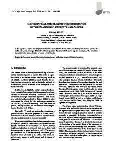
[email protected], Tel.: +48 32 603 4133, Department of Informatics, Faculty of Materials Engineering and Metallurgy, Krasinskiego 8, 40 019 Katowice, Poland Abstract The paper presents possibilities of controlling temperature field distribution in induction heated charge. The change of the distribution was obtained with use of sequential two-frequency heating. The study was conducted as multi-variant computer simulations of strongly coupled to each other field: the electromagnetic and the temperature fields. For the analysis, the professional calculation package using the finite element method Flux 3D was used. The problem of obtaining an appropriate temperature distribution in a heated charge of, a complex shape is very important in many practical applications. A typical example is a quenching of gears. For such applications, it is required to obtain a surface and in desired depth, uniform temperature distribution on the tooth face and top land and on the bottom land of the gear. The obtained temperature should have proper distribution and value. Achieving such a defined distribution is very difficult. During the study over a dozen different calculation variants were examined. Keywords: quenching, induction heating, gears, coupled electromagnetic-thermal calculation 1 Introduction Induction hardening is a metallurgical process whose purpose is to bring about local changes in the crystalline structure of surface layers of steel bodies resulting in their higher hardness [1–5]. The required parts of the body are first heated somewhat above temperature Ac3 securing their uniform austenite internal structure. Then, after eventual equalization of temperatures, the body is intensively cooled by a suitable quenchant. The result is harder, but brittle martensite structure of the hardened parts. The structure of the rest of the body (its core) remains unchanged [6-9]. The situation is indicated in Fig. 1. The figure shows several curves of cooling of typical carbon steel (41Cr4) from a starting temperature exceeding Ac3. Hardness (here in Vickers) HV is a function of the time t of cooling. The higher the velocity of cooling, the harder structure we obtain (see the curves on the left). The other curves (on the right) pass, however, through the area of bainite, pearlite or ferrite [10-12]. DOI 10.12776/ams.v20i2.311
p-ISSN 1335-1532 e-ISSN 1338-1156
153
Acta Metallurgica Slovaca, Vol. 20, 2014, No. 2, p. 152-159
T (°C) Ac3 = 801 °C 800 F
700 600
Ac1 = 736 °C
P
500 400
B
Ms = 382 °C
300 M 200 100 0 –1 10
hardness (HV)
660 10
0
636 10
571 1
350 262 10
2
t (s)
211 10
193 3
179 10
4
105
Steel 41Cr4, austenitizing temperature 840 °C, time of austenizing 600 s
Fig. 1 CCT diagram of typical carbon steel 41Cr4 (AISI 5140); M – martensite, B – bainite, P – pearlite, F – ferrite, Ac3 – at this temperature steel exhibits uniform austenite structure Ms – temperature of the transition to martensite structure The paper deals with the computer modelling of induction hardening of a teeth wheel. Its purpose is to harden their surfaces in order to increase their wear resistance [13]. The scheme of the arrangement is in Fig. 2. Real view of gear is in Fig. 3.
Fig. 2 Induction hardening of a teeth wheel, 1 – inductor, 2 – gear wheel, 3 - axes of symmetry
Fig. 3 Real view of a teeth wheel
2 Mathematical Model The mathematical model of the problem is given by two partial differential equations describing distributions of harmonic electromagnetic field and nonstationary temperature field [14-20]. rot
1
rot A (v rotA) J z
where:
(1)
A - denotes vector potential V.s/m, - the electrical conductivity S/m, - the magnetic permeability H/m, Jz - uniform density of the external currents A/m2, v - the relative speed of the inductor with respect to the charge m/s.
DOI 10.12776/ams.v20i2.311
p-ISSN 1335-1532 e-ISSN 1338-1156
Acta Metallurgica Slovaca, Vol. 20, 2014, No. 2, p. 152-159
154
This equation must be supplemented with a correct boundary condition – in this case of the Dirichlet or Neumann type. Distribution of nonstationary temperature field in the wheel is given by the heat transfer equation [4] div ( grad T ) c(v grad T ) c
T pv t
(2)
where: - denotes the thermal conductivity of the material W/(m .K), - its specific mass kg/m3, c - its specific heat at a constant pressure (all previous coefficients being functions of temperature) J/kg K, pv - the specific average Joule in the material losses given as W/m3. pv
J J
(3)
where: J denotes the density of eddy currents induced in the heated wheel A/m2. J
A t
(4)
This is given by the formula. The boundary conditions have to include convection and radiation. The 3D computation of the problem was realized by the finite element method, using the code FLUX3D supplemented with a number of own procedures and scripts. A considerable attention was paid to selected numerical aspects of the solution, mainly to the convergence of results in the dependence on the density of discretization meshes for both magnetic and temperature field and also on the position of the artificial boundary in the case of magnetic field [21-24]. 3 Results The hardened wheel for automotive industry with 20 teeth is made of steel 41Cr4 (see Fig. 1). Its principal dimensions are given in Table 1 and its thickness is 6 mm. The Curie temperature of steel 41Cr4 TC = 760 °C, the austenitizing temperature AC3 = 801 C [10]. Table 1 Principal dimension of gear Dimension Symbol [mm] 30 1 94 2 104 3 114 4
Designation internal diameter the gear external diameter the gear diameter between the teeth internal diameter of inductor
The physical parameters (as functions of the temperature) follow: 1
(T )
1
0
(1 T )
DOI 10.12776/ams.v20i2.311
(5)
p-ISSN 1335-1532 e-ISSN 1338-1156
155
Acta Metallurgica Slovaca, Vol. 20, 2014, No. 2, p. 152-159
where: 0 = 3,3106 Sm = 0,358 10-6 K-1
(T ) 0 (1 T )
(6)
where: 0 = 33 Wm-1K-1 = 0
c(T )
E 2
e b (V0 Vi )e
T
Vi
(7)
where: E = 6108 J/m3, 1 T Tc 2 b ( ) , 2 = 20 C, V0 = 0,38107 J/m3/C, Vi = 0,57107 J/m3/C, = 550 C, B( H , T ) 0 H
2 J s0 π(μ r 0 1) 0 H arctg ( ) f (T ) π 2 J s0
(8)
where: Js0 = 2 T, r0 = 600 H/m, T Tc
f (T ) 1 e f (T )
C
T2 T 10 e C
for T Tc
(9)
for T Tc
where: C = 0.4, c = 15 Wm–2K–1, = 0.7 (emissivity). First, the field current in the inductor is set to 4500 A at the frequency f = 10 kHz. At the moment when the average temperature of the tooth root reaches 1000 °C, the current source is switched and the final part of heating is realized by the field current 1300 A at the frequency f = 100 kHz. The total time of heating is approximately 10.8 s, the time of cooling is 10 s.
Fig. 4 The solved part of the arrangement DOI 10.12776/ams.v20i2.311
Fig. 5 Selected points of the tooth p-ISSN 1335-1532 e-ISSN 1338-1156
Acta Metallurgica Slovaca, Vol. 20, 2014, No. 2, p. 152-159
156
Due to the symmetry, it is sufficient to analyze the part of the wheel according to Fig. 4 (containing one half of the tooth). The thickness of this part is 3 mm (one half of the thickness of the wheel). The number of DOFs for electromagnetic computations was about 26000, for thermal computations about 5000. The computation of one example took approximately 8 hours. Fig. 5 shows a detail of the tooth with 20 points A1–A20, at the medium plane of the tooth where we checked the time evolution of the temperature. Fig. 6 shows the profiles of the temperature at points A1-A11 at selected time steps. It is obvious that its distribution along the particular time levels is fairly homogeneous. The pictures (Fig. 7-9) show final magnetic induction, Joule (Power) Losses and temperature distribution on the tooth surface.
Fig. 6 Time evolution of temperature at points (A1-A11)
Fig. 7 Magnetic induction distribution on the tooth surface DOI 10.12776/ams.v20i2.311
p-ISSN 1335-1532 e-ISSN 1338-1156
Acta Metallurgica Slovaca, Vol. 20, 2014, No. 2, p. 152-159
157
Fig. 8 Joule (Power) losses distribution on the tooth surface
Fig. 9 Temperature distribution on the tooth surface after 10,8 s. 4 Discussion This work presents numerical simulations of the induction heating. Such simulations contain the analysis of coupled electromagnetic and thermal fields. Analysis of the induction heating process of gear wheels seems to be a very complex process. This is mainly caused by the large number of parameters that have a decisive influence on the final result. In addition, the necessity of multiple calculations and changing the selected parameter to achieve the assumed temperature causes the large number of calculations. 5 Conclusions The main conclusions are the following: (1) during the test quenching of the gear a problem of non uniform temperature distribution appears, (2) the attempts of experimental selection of heating parameters failed, and the problem was solved by multi-variant calculations, DOI 10.12776/ams.v20i2.311
p-ISSN 1335-1532 e-ISSN 1338-1156
Acta Metallurgica Slovaca, Vol. 20, 2014, No. 2, p. 152-159
158
(3) the results obtained from calculations were successfully applied in the quenching process, (4) as the time of cooling below the martensite temperature is about 10 s, the resultant hardness of the surface layers of the tooth is about 641 HV. References [1] A. Kohli, H. Singh: Sadhana, Vol. 36, 2011, No. 2, p. 141–152, DOI: 10.1007/s12046-0110020-x [2] M. Niklewicz, A. Smalcerz, A. Kurek: Przeglad Elektrotechniczny, Vol. 84, 2008, No. 11, p. 219-224 [3] F. Biasutti, Ch. Krause, S. Lupi: International Magazine for Industrial Furnaces Heat Treatment and Equipment, 2012, No. 3, p. 59–70 [4] R. Burdzik, P. Folęga, B. Łazarz, Z. Stanik, J. Warczek: Archives of Metallurgy And Materials, Vol. 57, 2012, No. 4, p. 987-993, DOI: 10.2478/v10172-012-0110-8 [5] B. Oleksiak, G. Siwiec, A. Blacha, J. Lipart: Archives of Materials Science and Engineering, Vol. 44, 2010, No. 1, p. 39-42 [6] B. Bul'ko, J. Kijac, P. Demeter, J. Demeter: Acta Metallurgica Slovaca, Vol. 17, 2011, No. 1, p. 51-57 [7] A. Smalcerz, R. Przylucki, K. Konopka, A. Fornalczyk, M. Slezok: Archives of Materials Science and Engineering, Vol. 58, 2012, No. 2, p. 177-181 [8] A. Candeo et al.: IEEE Transactions on Magnetics, Vol. 47, 2011, No. 5, p. 918-921, DOI: 10.1109/TMAG.2010.2073682 [9] G. Parris, D. Ingham: Gear Technology, The Submerged Induction Hardening of Gears, 2008, p. 28–40 [10] J. R. Davis: Gear Materials, Properties, and Manufacture, ASM International, 2005 [11] J. Barglik, A. Kurek, D. Dołęga, et al..: Induction hardening of gear wheels – numerical simulation, EPE, Czech Republic, CD-ROM, 2009, p. 319-323 [12] S. Lupi, F. Doughiero, M. Forzan: Modelling single- and double-frequency induction hardening of gear-wheels, EPM, Sendai, 2006, p. 473-478 [13] C.H. Gur, J. Pan: Handbook of Thermal Process Modeling of Steels, CRC Press, 2008, p. 27-498 [14] J. Barglik, R. Przylucki, et al..: Influence of an Industrial Robot on the Electromagnetic Field Distribution Around the High Frequency Induction Heater, EPE 2011, Czech Republic, CD-ROM, 2011, p. 693 - 696 [15] A. Smalcerz, R. Przylucki: Metalurgija, Vol. 52, 2013, No. 2, p. 223-226 [16] A. Fornalczyk, S. Golak, R. Przyłucki: Przeglad Elektrotechniczny Vol. 89, 2013, (3A), p. 57-60 [17] A. Smalcerz: Archives of Metallurgy and Materials, Vol. 58, 2013, No. 1, p. 203-209, DOI: 10.2478/v10172-012-0174-5 [18] A. Fornalczyk, R. Przyłucki, M. Saternus, S. Golak: Archives of Materials Science and Engineering, Vol. 58, 2012, No. 2 , p. 199-204 [19] A. Smalcerz, R. Przylucki: International Journal of Thermophysics, Vol. 34, 2013, No. 4, p. 667-679, DOI: 10.1007/s10765-013-1423-1 [20] J. Barglik, A. Kurek, R. Przylucki, A. Smalcerz, M. Slezok: Acta Technica CSAV, Vol. 57, 2012, No. 1, p. 61-73 [21] A. Candeo, P. Bocher, F. Dughiero: Multiphysics Modeling of Induction Hardening of Ring Gear, HES, Padova, 2010, p. 627-634 DOI 10.12776/ams.v20i2.311
p-ISSN 1335-1532 e-ISSN 1338-1156
159
Acta Metallurgica Slovaca, Vol. 20, 2014, No. 2, p. 152-159
[22] M. Niklewicz, A. Smalcerz: Przeglad Elektrotechniczny, Vol. 86, 2010, No. 5, p. 333-335 [23] M. Cerrone, F. Dughiero, M.Forzan, F. Pelissero, M. Spezzapria: Numerical simulation of induction hardening of gears for aeronautical industry, HES, Padova, 2013 [24] R. Przylucki, A. Smalcerz: Metalurgija, Vol. 52, 2013, No. 2, p. 235-238 Acknowledgements Authors are grateful for the support of experimental works by project No N N508 479438.
DOI 10.12776/ams.v20i2.311
p-ISSN 1335-1532 e-ISSN 1338-1156