mated or remote operated shovel could use the 3D map ob- tained with the ... Optikk (NEO) for his technical support with the hyperspectral scanners. A similar ...
3D GEOLOGICAL MODELLING USING LASER AND HYPERSPECTRAL DATA Juan I. Nieto, Sildomar T. Monteiro∗
Diego Viejo
Australian Centre for Field Robotics University of Sydney Australia
Department of Computer Science and AI University of Alicante Spain
ABSTRACT This paper presents a ground based system for mapping the geology and the geometry of the environment remotely. The main objective of this work is to develop a framework for a mobile robotic platform that can build 3D geological maps. We investigate classification and registration algorithms that can work without any manual intervention. The system capabilities are demonstrated with data acquired from a working mine environment. Geological maps are built by applying classification techniques to hyperspectral images of the rocks’ surface. The result from the classification is then fused with laser images to form the 3D geological models of the environment.
A similar approach is presented in [1]. The authors use range sensors and hyperspectral cameras for a case study of a dolomite and limestone quarry. The most important difference with the framework presented in this paper is in the form in which the data fusion is done. While we use only natural features for the sensors’ registration, the approach presented in [1] uses retro-reflective targets to register laser and images. Another important difference is that in [1] the image is manually partitioned in sections followed by a bundle adjustment process. The approach presented in this paper uses Delaunay triangulation to automatically partition the image before a piecewise linear transformation. 2. MATERIALS AND METHODS
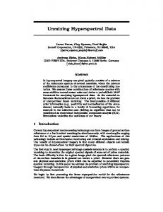
1. INTRODUCTION This paper aims at developing a framework that can obtain a detailed 3D geological map of the environment without any manual intervention. The advents of optics and electronics has enabled the development of commercial multi and hyperspectral sensors making this technology accessible not only for military and government applications but also for civil applications such as mining and agriculture. In particular, we concentrate in the construction of 3D geological maps of the environment. A 3D laser and a hyperpsectral camera are mounted on a vehicle. The laser is used to capture geometry and the hyperspectral sensor captures spectral characteristics of the environment. By fusing the information of the two sensors we are able to build 3D geological maps. Figure 1 shows a diagram with an overview of the proposed framework. A main application of our framework is in spatial control and classification of material in mining excavation. An automated or remote operated shovel could use the 3D map obtained with the system presented. Having access to real-time information of the geometry and mineralogy of the mine face could give an estimate of the ore-grade and volumes being excavated. ∗ This project is funded by the Rio Tinto Centre for Mine Automation. We want to thanks to Annette Pal from RTIO, for all the help and support during the field trials. We also like to thank to Trond Loke from Norsk Elektro Optikk (NEO) for his technical support with the hyperspectral scanners.
978-1-4244-9564-1/10/$26.00 ©2010 IEEE
4568
Reflectance and emittance spectroscopy of natural surfaces are sensitive to specific chemical bonds in materials. The advantage of spectroscopy is that it can be used at close ranges (laboratories) or far away (satellites). The main disadvantage is that it is sensitive to small changes in the chemistry and/or texture of the material. The variations in material composition often cause shifts in the position and shape of spectral features. Thus, in the real world, spectral features can be quite complex [2]. Nevertheless, spectroscopy has a great potential to estimate or classify key geological properties. Hyperspectral remote sensors collect data in hundreds of bands. These measurements produce a “continuum” spectrum that, after adjustments and corrections, can for example, be compared with libraries of reflectance spectra. Typically, hyperspectral cameras collect all spectra across a spatial line in the image. Then, some form of scanning is required in order to build up a spectral image. The scanning can be done by either camera movement (rotation or translation) or movement of the scene (e.g. conveyor belt). Expert systems have been shown to be effective for mineral mapping [3]. The main drawback of these systems is that they require a large amount of input from an expert user. For example, in Tetracorder [3], each comparisson of an unknown to a reference spectrum is highly tailored to the chemistry of the reference material. We want to focus on methods that require none or little input from a human or a priori expert
IGARSS 2010
Fig. 1. Framework overview of hyperspectral image and laser data registration knowledge. The next paragraphs explain the algorithm used for the classification. The first step for thematic mapping is to find the endmembers. In this paper, we apply Sequential Maximum Angle Convex Cone (SMACC) spectral algorithm, which extract endmembers from the images. SMACC uses a convex cone model (also known as Residual Minimization) to identify image endmember spectra. Extreme points are used to determine a convex cone, which defines the first endmember. A constrained oblique projection is then applied to the existing cone to derive the next endmember. The cone is increased to include the new endmember. The process is repeated until a projection derives an endmember that already exists within the convex cone (to a specified tolerance) or until the specified number of endmembers are found [2]. Hyperspectral data processing is problematic due to its high dimensionality [4]. However, the data presents high correlation. The correlation between spectral bands arises from a combination of factors; material spectral correlation, topography (shading introduces correlations), and sensor band overlap [5]. In addition to the correlation between bands, a proportion of the variance exhibited by the data is noise. In the experiments presented here we use Principal Component Analysis (PCA). The principal component transformation is a feature space designed to remove this spectral redundancy. In PCA, the new features are a linear function of the original data, and the aim is to obtain a new space that captures as much of the variance as possible. The result is that a new space is formed by the eigenvectors of the original data covariance matrix. The final step is the classification itself. We use spectral similarity. One of the most effective methods using spectral similarity is Spectral Angle Mapper (SAM) [6]. The algorithm determines the spectral similarity between two spectra by calculating the angle between the spectra and treating them as vectors in a space with dimensionality equal to the number
4569
of bands. This technique, when used on calibrated reflectance data, is relatively insensitive to illumination and albedo effects. 2.1. Registration of Hyperspectral Image and Laser data Once the thematic mapping is completed, we register the resulting mineral classification with the 3D data collected with the laser. In this paper we use a Riegl 3D Laser. Different data representations are possible, from raw data to parametrised models. For the work presented in this paper we use the raw data points with RGB colour sumperimposed. The colour is obtained from a calibrated commercial camera sitting on top of the laser. A common registration method used for image-laser registration is to use a checkerboard [7, 8]. We implemented a method that does not require manually selected control points. The basic idea consists in finding the correspondences between hyperspectral image pixels and 3D points. The first step is to transform the 3D point set into a 2D image by projecting each 3D point onto a cylinder. A 3D point P(x,y,z) can be transformed in a 2D image pixel P’(i, j) using a panoramic model [9]. The images are then registered with hyperspectral data using control points followed by a spatial transformation. The control points are automatically selected using Scale Invariant Feature Transform (SIFT) [10]. Control points are matched by looking for the two closest features in the space of SIFT descriptors. Two points are finally matched if the distance to the closest one is less than a certain value of the distance to the second closest (e.g. 0.6 was used for the implementations presented here). Mismatched points are removed by enforcing viewpoint consistency constraints. In the experiments shown in this paper, we use both, a piecewise linear and a polynomial transformation. Figure 2 shows a block diagram of the registration process.
(a)
(b)
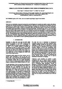
Fig. 3. (a) Original pixel spectra. (b) shows the spectra after IMNF followed by a Gaussian low pass-filter. Wavelengths are in nm.
Fig. 2. Automatic image registration overview.
Once we have computed the transformation that aligns hyperspectral and laser projected images, we project back previously extracted thematic maps onto 3D laser data by means of the same cylindrical projection model. Each 3D point is projected again onto the panoramic image registered with hyperspectral. If the projection of the point belongs to the overlapping panoramic-hyperspectral image area, the 3D point is labelled with the corresponding geological classification. Using this method we can obtain a geological 3D map of the environment.
Fig. 4. Mean spectra reflectance for the endmembers found by the SMACC algorithm.
3. EXPERIMENTS 3.2. Thematic Mapping Experimental data was collected in an open pit mine in Western Australia. A Riegl LMS-Z420i laser was used to collect range data and a Neo HySpex VNIR camera was use to acquire hyperspectral images. Data was collected in different parts of the mine, during two days, in mostly sunny conditions. Image normalisation (reflectance) was performed using a calibration board next to the target.
3.1. Noise Reduction Our main concern is with global noise, which is characterized by a random variation of the DN value at every pixel. Smoothing filters are the most common technique used to remove global random noise. Low-pass spatial filters can effectively reduce noise variance, particulary if it is uncorrelated from pixel to pixel. Unfortunately, they also reduce the variance of the noiseless signal, this having a negative impact particularly on sharp signal features. Due to the scale of our problem, for this work we are not concerned with sharp features. After trying different noise reduction schemes, we found that using Maximum Noise Fraction (MNF) followed by a Gaussian smoothing filters was the most effective for our data. Figure 3 illustrates with an example the effectiveness of the noise reduction scheme.
4570
Figure 4 shows the mean spectra for two of the endmembers found by the SMACC algorithm. We also added two more endmembers, one representing the sky and one representing the darkest areas of the image. These last two do not have any useful value for the geology classification, but were selected to see the capabilities of SAM. Figure 5 shows the mean spectra for clusters obtained using SAM. The blue and green clusters show the main absorption band feature of iron-ore at about 860 nm, indicating the presence of this mineral in those clusters. The mean spectra also shows an extra absorption band at about 680 nm which indicates the mixture of minerals. However, finding a solution for the mixing problem is beyond the scope of this paper. 3.3. Sensors Registration To get the volume, the thematic map needs to be registered with the laser information. The first step for the registration is to generate control points in both data. To generate them automatically we use SIFT [10]. We obtain about 2000 SIFT from each hyperspectral image and more than 5000 from a 3D laser projected image. After matching them and removing outliers it remains about 200 SIFT matches between both images. Figure 6 shows the result using SIFT features and a piecewise linear transformation. The registered hyperspectral im-
Fig. 5. Mean spectra reflectance for the clusters obtained using SAM. Note that the red one is the cluster representing the sky.
Fig. 7. Geological 3D model. The mineral classification is mapped onto the 3D data. togrammetry, Remote Sensing and Spatial Information Sciences, 2008, pp. 1229–1234. [2] R. N. Clark, Remote Sensing for the earth Sciences, vol. 3, chapter Spectroscopy of rocks and minerals, and principles of spectroscopy, pp. 3–58, John Wiley & Sons, New York, USA, 1999.
Fig. 6. Registered hyperspectral image overlaid on top of 2D laser image. Transparency was set to 50%. The figure shows the result using SIFT and a piecewise transformation. age was overlaid on the 2D laser image. We set transparency to 50% so areas with a bad registration look blurred. We found that the areas with bigger registration errors are the ones with poor control points distribution. Finally, Figure 7 shows the resulting 3D geological map. 4. CONCLUSIONS We demonstrated that the two main processes (i) classification and (ii) registration can be done without any manual input. We believe the framework presented can enable automation in applications requiring geology estimation in conjunction with geometry data. In future work, we plan to investigate the use of machine learning algorithms to improve our current results. We also intend to test different local invariant feature algorithms to select the control points.
[3] R. N. Clark, G.A. Swayze, K.E. Livo, R.F. Kokaly, S.J. Sutley, J.B. Dalton, R.R. McDougal, and C.A. Gent, “Imaging spectroscopy: Earth and planetary remote sensing with the USGS Tetracorder and expert systems,” Journal of Geophysical Research, vol. 108, no. E12, pp. 5131, 2003. [4] Brandt Tso and Paul M. Mather, Classification Methods for Remotely Sensed Data, Taylor & Francis, 2001. [5] Robert A. Schowengerdt, Remote Sensing: Models and Methods for Image Processing, Elsevier, 2007. [6] Freek van der Meer, “The effectiveness of spectral similarity measures for the analysis of hyperspectral imagery,” International Journal of Applied Earth Ovservation and Geoinformation, vol. 8, no. 1, pp. 3–17, 2005. [7] Q. Zhang and R. Pless, “Extrinsic calibration of a camera and laser range finder (improves camera calibration),” in IEEE International Conference on Intelligent Robots and Systems, 2004, vol. 3, pp. 2301–2306. [8] J. Underwood, S. Scheding, and F. Ramos, “Real-time map building with uncertainty using colour camera and scanning laser,” in Australasian Conference on Robotics and Automation, Brisbane, Australia, 2007. [9] D. Schneider and H.G Mass, “A geometric model for linear-array-based terrestrial panoramic cameras,” The Photogrammetric Record, vol. 21, pp. 198–210, 2006.
5. REFERENCES [1] T. H. Kurz, S. J. Buckley, J. A. Howell, and D. Schneider, “Geological outcrop modelling and interpretation using ground based hyperspectral and laser scanning data fusion,” in The International Archives of the Pho-
4571
[10] David G. Lowe, “Distinctive image features from scaleinvariant keypoints,” The Photogrammetric Record, vol. 60, pp. 91–110, 2004.