3D UWB Radar Super-Resolution Imaging for complex Objects with discontinous Wavefronts R. Salman, I. Willms Fachgebiet Nachrichtentechnische Systeme Universität Duisburg-Essen 47057 Duisburg, Germany E-Mail:
[email protected] Abstract—This paper deals with problems related to the accurate identification and super-resolution Ultra-wideband (UWB) imaging of complex shaped 3D Objects. Current state of research solves the related upcoming challenges by just using inverse scattering algorithms and a 2D scan track (which provides only a limited perspective) or applying such algorithms only to objects with rather simple concave or convex contours. But a full perspective of the object needs circumnavigation to extract entirely all stereoscopic distributed contour pixels. The applicability of the known Range Points Migration (RPM) is investigated. In order to reconstruct a full 3D object contour, the so far planar scanning of the antennas is modified and extended to a spatial scanning including the z-axis. An experimental validation is carried out based on complex test objects with small shape variations relative to the used wavelength, an M-sequence Radar device and double ridged horn antennas. Index Terms—3D UWB imaging, UWB sensing, fuzzy logic UWB imaging, super-resolution UWB imaging.
I.
INTRODUCTION
UWB Radar provides new perspectives for contactless microwave sensing, imaging and localization applications. Especially in near-field indoor applications it has various superior advantages in contrast to classical sensing techniques. UWB Radar can operate in dark and dust or smoke filled environments where other imaging or ranging approaches based on ultrasound, infrared or optics typically fail. The large bandwidth, i.e. about 9 GHz used within these investigations, results in a fine time resolution which enables resolution in sub-centimetre range. Due to the large range of available frequencies and especially the lower ones, UWB Radar systems are able to penetrate dielectric materials to perform subsurface imaging [1]. Various Radar algorithms have been developed mostly based on SAR [2], time-reversal algorithms [3] and migration inspired ones [4] but all suffer from vast computational load and/or inadequate image resolution. In contrary, it was shown that the inverse boundary scattering transform (IBST) and IBST inspired algorithms are a simpler and more computationally efficient UWB imaging algorithm which determines the direction of Radar responses based on changes of the round-trip times. Since the introduction of the original
IBST [5] there has been significant research effort for improvements by extending it to 3D, bistatic configurations and non-planar tracks [6]. However, IBST utilizes the derivative of the received data and hence is sensitive to noise. Moreover it is hard to apply for complex objects with multiscattering behaviour and discontinuous wavefronts. In [7] an imaging algorithm called RPM was proposed that utilizes fuzzy estimation for the direction of arrival (DOA). It extracts a direct mapping by combining the measured distance of the wavefront with its DOA. Moreover it realizes a stable imaging of even complex objects and requires neither preprocessing like clustering or connecting discontinuous wavefronts nor any derivatives. The 2D RPM was introduced in [7] for a planar sensor track nearby the object only which allows either only a limited image of the lateral region of the object or would require immense scan distances. Consistently, the back region of the object is not scanned and hence not imaged. In [8] RPM was extended to 3D where the sensors are placed on a planar surface in front of the 3D object. However, this 2D sensor track also avoids a full perspective of all stereoscopic distributed contour pixels of a 3D Object. In this paper the 2D RPM algorithm is investigated with regard to an extension to a spatial scanning in order to improve the perspective limitations of a planar track. For practical application and to reduce mechanical effort the object is scanned circularly. Subsequently, the 3D scenario is investigated by adding the zaxis and performing the circular tracks on different heights. Algorithms are investigated to extract a 3D image of aforementioned multiple 2D Scans. All extended algorithms are experimentally validated and results are shown. II. HARDWARE SETUP The used Radar system consists of a UWB Maximum Length Binary Sequence (M-Sequence) Radar system [9] with an operating band of DC – 4.5 GHz. For higher time resolution an additional IQ up-converter was used which modulates the waveform to a carrier frequency of 9 GHz. Two double-ridged horn antennas with an opening angle of approximately 20° in the operational bandwidth were mounted
one upon the other. The difference of the round-trip time of a monostatic configuration and the collocated quasi-monostatic configuration is negligible. The emulation of the free movement of a mobile robot platform is provided by two symmetric arrangements of linear rails including rotatable platforms, all operated by highly accurate step motors. Used objects have clear metallic surface to provide strong echoes. III.
SYSTEM SETUP,
m g is ambiguous because both circles around m and g antenna coordinates intersect twice. Since directive horn antennas are used the intersection outside the antenna track can be discarded. The angular estimation of the DOA for the mth antenna relies on the convergence of nearby wavefronts g 1, 2,..., G to the wavefront m if the positions of each gth antenna position moves towards the mth one. A Gaussian membership function
IMAGING ALGORITHMS AND FIRST RESULTS
-m g
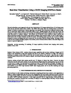
A. 2D Imaging Algorithm In Fig. 1 the measurement setup of a 2D circular track is shown. The investigated object is a rectangle of 12 x 30cm2 and is located at D = 40cm in front of the sensors. The measurements are performed on a circular track around the object using a 1° grid from 0° to 359°.
2 θ2
f ( , X g , Z g ) e
2
(3)
is used to perform the fuzzification of the so called crisp set determined in (2). The fuzzification is performed for g 1, 2,..., G both to the right and to the left side of the mth antenna position, respectively. This results in 2G neighbouring antenna positions with which the DOA of the actual mth antenna is determined. A defuzzification provides the estimation of the DOA in the form of
opt arg max
2 m - g 2G 2 x2 , ( , , )e s X Z f X Z g g g g g 1
(4)
by taking that value of for which the accumulation maximizes. Here, s X g , Z g is a scaling factor of the membership functions and equals the absolute value of the reflection peak. Hence, the image coordinates (x, y) for each antenna coordinates (X, Y) are defined as Figure 1. Measurement setup of the 2D circular track
To span a complex coordinate system with the origin in the 1st antenna position, the antenna coordinates (X, Y) are defined as
j -90 e j90 X Re D e Y Im D e j -90 e j90
0,1,...,359.
(1)
The distance of the measured wavefront in position is Z . Assuming that the connection between the antenna positions m and g is the hypotenuse of a triangle and assuming both measured distances at each end of the hypotenuse as the arms, then the intersection angle for m between the hypotenuse and the intersection point is defined as m g arg
X
m
jYm X g jYg
X m jYm X g jYg Z m Z g arccos 2 X m jYm X g jYg 2 Z m 2 2
2
2
.
(2)
jopt x Re X m +jYm Z m e y Im X m +jYm Z m e jopt
.
(5)
The crucial parameters of these algorithms are θ and x . In recent publications both constants were determined empirically. Actually, these two constants seem to have immense influence on the imaging due to own investigations. θ can be considered to be the standard deviation of the Gaussian membership function and x acts with the 3rd multiplier as another scaling factor. x and θ have vast influence onto the shape of the Gaussian membership functions and therewith onto the accumulation performed in (4). However, depending on the chosen values of x and θ more or less the influence of wavefronts of neighbouring antenna positions can be taken into account. For further investigations of the imaging algorithm θ is defined as 2 θ fuzzy _ angle
loge 4
(6)
G2 log G _ percent 2 e
(7)
with G _ percent 0.1,0.2,...,0.9. The 3rd factor of equation (4) provides an attenuation of the set of 2G neighbours , i.e. the farther the neighbouring sensor is away, the less is the influence in the algorithm. With the explicit definition of x in (7) the degree of attenuation can be controlled and adapted to the scenario. In such a way using the parameterized definitions of x and θ the investigation of the resulting images and the design of the algorithm was performed. An object with a square cross-section of 18 x 18cm2 was used for measurements to determine optimized parameter settings. The results are shown in following figures: 0.5
Figure 3: Results with various parameters for fuzzy_angle = 5
G_percent 0.1
0.5
0.9
0.9
50
G 90
10
50
5
10
G_percent 0.1
G 90
5
x
50
with fuzzy _ angle 1, 2,...,10 determining the Gaussian membership function. The factor x utilizes a scaling within the 3rd factor of equation (4) and can be parameterized as
G 90
Figure 4: Results with various parameters for fuzzy_angle = 10
Figure 2: Results with various parameters for fuzzy_angle = 1
G 10
5
G_percent 0.1
0.5
0.9
It is recognizable that the more neighbouring antennas are regarded (increasing G) the more highlighted the edges are. This effect is extremely amplified if also the antennas being farthest away are less attenuated (increasing G_percent). This is used in current research for characterizing an object by its reflective features (edges and corners) to perform UWB object recognition [10]. Best images are determined with wellbalanced parameters of G = 5…10 neighbouring positions and an attenuation of G_percent = 0.5 at a fuzzy_angle = 5 degree. For this case the focus of 5-10 neighbouring antennas is restricted enough to avoid the overbalanced effects of edges as it would be the case for antennas being farther away. The image points are then nearly equidistantly distributed over the whole contour so that a high level of accuracy and resolution can be achieved. In consideration of the fact, that a quasi monostatic antenna configuration is used within these investigations, the above shown results are quite feasible. A strong echo, i.e. a specular
reflection is received only, when the main lobe of the antenna is aligned to the normal of a smooth surface of the object. However, in case of a circular track this occurs very rarely, if the cross-section of the object is not a circle. Scattering and diffraction effects overbalance immensely within a circular track, even more if the scan track is spread over a large circular arc. But weak echoes spread spherically from the edges and can be recorded from any line of sight position.
by taking the maxima giving the wanted azimuth and elevation angle. In combination with the measured radial distance a clearly defined spherical image point can be determined. The following figures show examples of experimental validations.
These settings gained in the investigations described above are the basis for extension investigations to 3D in the following. B. 3D Imaging Algorithm Both the scan track and the algorithm for the 3D Imaging are based onto the 2D scenario. The scan track is once again a circular track which is performed at different heights. Depending on the resolution requirements a grid of 2-3 cm in z-direction is sufficient for adequate 3D UWB images. However, the trivial superposition of multiple 2D images to one 3D image extracts a false image, since the DOA of the wavefronts is perpendicular to the scanned surface and not implicitly on the same level like the sensors. For the extension to 3D the space is described by spherical coordinates with the measured distance of the wavefront corresponding to the radial distance. Combined with an azimuth and elevation angle an image point can be clearly determined. For a 3D object with a simple shape with no contour variance in the z-axis, e.g. a cylinder or a column, it would be necessary to apply the 2D algorithm twice to horizontal and vertical dimension. However, in case of complex objects with diagonal contour in z-domain, e.g. a cone, this cannot work. For a correct estimation of the DOA in horizontal dimension the same accumulations from equation (4) for the 2D case are repeated for N v positions above and below the antenna at the considered height value. The exact number of N v depends on the resolution requirements and the scanning grid in vertical dimension. In experimental validations within this paper the objects with a height of about 70 cm were measured using a 2 cm grid and N v 20. To involve the nv 1, 2,..., N v accumulation to the one considered and therewith to get the neighbouring influence to extract the correct DOA the nv -th accumulation is weighted by n wv 1 v . (8) Nv 1 The estimation of the DOA in vertical and horizontal dimension is performed in same way with equations (8) and by computing the accumulations left and right beside the actual one as well as above and below the actual one. So the resulting new accumulations contain the DOA information including the neighbouring information from above/below and left/right for horizontal and vertical dimension, respectively. The defuzzification is performed again for each accumulation
Figure 5: Test object with a shape of a cone and UWB image
Figure 6: Test object with a shape of 2 cones and UWB image
the bottle in figure 8 or the upper boundary of object in figure 7 are still not perfect. Due to the limited z-movement the hemisphere is marked only by a few image points. The reconstruction of horizontal details is thus limited by the cylindrical scan and would be improved by e.g. spherical scanning. To some extent polarimetric measurements can improve horizontal details. Within these investigations measurements were performed in vertical-vertical polarization. Future research will focus on full polarimetric measurements to improve UWB image quality by exploiting polarimetric diversity gain. It can be concluded that the introduced method represents a powerful algorithm for comprehensive 3D shape reconstruction and imaging tasks which is usable in many fields of contactless microwave sensing, e.g. medical, defense and security applications. ACKNOWLEDGMENT
Figure 7: Test object with a big water bottle on a metallic column and UWB image
The authors thank the Deutsche Forschungsgemeinschaft (DFG) for the support of the work as part of the “Cooperative Localisation and Object Recognition in Autonomous UWB Sensor Networks” (CoLOR) project within the UKoLoS priority program. REFERENCES [1]
Figure 8: Top view of UWB images
C. Discussion and Conclusion In this paper we introduced a new method which extends the common RPM to full 3D antenna movements in order to reconstruct more information of the object shape than it is possible based on only planar scanning. The efficiency of this idea was validated by measurements. But it can be seen that the reconstruction of horizontal details, e.g. the platform under
R. Salman, I. Willms, “In-wall object recognition based on SAR-like imaging by UWB-Radar,” 8th European Conference on Synthetic Aperture Radar, EUSAR 07.-10. June 2010, Eurogress, Aachen. [2] D.L. Mensa, D. Heidbreder, G. Wade, “Aperture synthesis by object rotation in coherent imaging,” IEEE Trans. Nucl. Sci., vol. NS-27, no. 2, pp. 989-998, Apr. 1980. [3] D. Liu, J. Krolik, L. Carin, “Electromagnetic target detection in uncertain media: Time-reversal and minimum-variance algorithms,” IEEE Trans. Geosci. Remote Sens., vol. 45, no.4, pp. 934-944, Apr. 2007. [4] R.H. Stolt, “Migration by fourier transform,” Geophysics, vol. 43, no. 1, pp. 23-48, Feb. 1978. [5] T. Sakamoto, T. Sato, “A target shape estimation algorithm for pulse radar systems based on boundary scattering transform,” IEICE Trans. Commun. vol. E87-B, No.5, pp.1357-1365, May, 2004. [6] M. Helbig et al., “Preliminary investigations of chest surface identification algorithms for breast cancer detection”, 2008 IEEE Int. Conf. on Ultra-Wideband, ICUWB 2008, Hannover, Germany, Sept. 2008. [7] S. Kidera, T. Sakamoto, T. Sato, “High-speed UWB radar imaging algorithm for complex target boundary without wavefront connection,” presented at the XXIX General Assembly of URSI, Jul. 2008, BP17.2. [8] S. Kidera, T. Sakamoto, T. Sato, “Accurate UWB radar 3D imaging algorithm for complex boundary without range points connections,” IEEE Trans. Geoscience and Remote Sensing, vol.48, no. 4, pp.19932004, Apr. 2010. [9] J. Sachs, R. Herrmann, M. Kmec, M. Helbig, K. Schilling, “Recent advances and applications of M-sequence based Ultra-Wideband aensors,” ICUWB 2007 Singapore, September 24-26, 2007. [10] R. Salman, I. Willms, “A novel UWB Radar super-resolution object recognition approach for complex edged objects,”, IEEE International Conference on Ultra-Wideband (ICUWB), 20-23 Sept. 2010