Applying 3D animation methods to 3D video compression is not reasonable because 3D video has several different features which make it difficult to apply these ...
3D VIDEO COMPRESSION BASED ON EXTENDED BLOCK MATCHING ALGORITHM Seung-Ryong Han, Toshihiko Yamasaki, and Kiyoharu Aizawa Department of Frontier Informatics, The University of Tokyo 5-1-5 Kashiwano-ha, Kashiwa, Chiba 277-8561, Japan {zozonie, yamasaki, aizawa}@hal.k.u-tokyo.ac.jp frame coding is used for reducing spatial redundancy in each frame. From this point of view, 3D mesh compression techniques reported so far [6-8] are for intra frame coding. On the other hand, inter-frame coding exploits temporal redundancy. From this point of view, most of the previous inter-frame compression methods have been focused on 3D animation [8-13]. Ibarria et al. used space-time predictor which finds spatial and temporal redundancy between current and reference frame [9]. Gupta et al. exploited iterative closet point algorithm to group a vertex whose movement can be represented an affine transform matrix within a given threshold [10]. Their basic computation unit was a vertex and they assumed that topological information does not change with time. Guthe and Starßer applied the wavelet transforms and motion compensation framework to animated volume data [13]. However, their data are different from our polygon model. To our knowledge, inter-frame compression for 3D video has not been reported. We think this is because 3D video generation research has only recently been started and is still in their fancy [1-3]. Applying 3D animation methods to 3D video compression is not reasonable because 3D video has several different features which make it difficult to apply these methods to 3D video compression. The most significant problem is that no explicit correspondence exists between consecutive frames. The numbers of vertices and topological (connectivity) information are different from each other due to the non-rigid nature of human body and clothes. For this reason, vertex correspondence is calculated every consecutive frame if we use 3D animation compression scheme. Besides, each frame is a highly detailed model with more than 50,000 vertices. This means that iterationbased compression method [10] takes lots of time, and therefore, not practical. Finally, 3D video is noisy which means that 3D model has certain floating patches because it is obtained from multiple viewpoints silhouette images which are prone to be perturbed when extracting an object from background using chroma-key processing. 3D animation compression schemes are sensitive to such unexpected noise and the noise degrades the compression efficiency. In this paper, we propose a compression method for 3D video to encode geometric information in consecutive frames. Our method uses a block matching algorithm that is
ABSTRACT Three dimensional (3D) video is attracting a lot of attention as a new multimedia representation method. 3D video is a sequence of 3D models (frames) that consist of varying vertices and connectivity. In conventional 2D video compression algorithms, motion compensation (MC) using block matching algorithm is frequently employed to reduce redundancy between consecutive frames. However, there is no such technology for 3D video so far. Therefore, in this paper, we have developed an extended block matching algorithm (EMBA) to reduce temporal redundancy of geometry information of 3D video by extending the idea of 2D block matching to 3D space. In our EBMA, a cubic block is used as a matching unit and, MC is achieved efficiently by matching the mean normal vectors of the sub-blocks, which turned out to be sub-optimal by our experiments. The residual information is further transformed by discrete cosine transform (DCT) and then encoded. The extracted motion vectors are also entropy encoded. As a result of our experiments, compression ratio ranging from 10% to 18% of the original 3D video data has been achieved. Index Terms— 3D video, dynamic mesh, block matching algorithm, geometry compression 1. INTRODUCTION 3D imaging has been attracting attention for long time. One of the latest developments is 3D video generated from a number of views [1-3]. 3D video consists of a series of static 3D models that are generated frame by frame. Therefore, the number of vertices and connectivity of the geometry data varies with time. Such geometry data is also called dynamic mesh. Tomiyama et al. generated 3D video using volume intersection and stereo matching algorithm [2]. 3D video will have many applications in 3D content archive, communication, and entertainment. In particular, 3D video merges real and virtual world easily, thus demand for 3D video is growing up rapidly [4]. However, the data size of 3D video is quite large. For instance, each frame of 3D video in [2] consumes 5~10MB depending on its spatial resolution. Therefore, efficient compression is required. Typical methods for video compression have two compression modes, i.e., intra- and inter-frame coding [5]. Intra-
1424404819/06/$20.00 ©2006 IEEE
525
ICIP 2006
bic block sizes can produce better motion compensation results. However, a smaller block increases the number of motion vectors that need to be transmitted. After the splitting, we obtain a set of cubic blocks, Bi, where, i=0, …, N-1, and these cubic blocks are compared to the candidate blocks C in the previous frame Fi-1. In splitting, certain blocks have smaller number of vertices as compared to average number of vertices in cubic block. In that case, such cubic blocks are merged into their nearest neighbor cubic blocks.
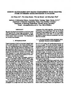
(a) (b) Fig. 1. Sub-blocking: (a) previous (reference) frame, (b) current frame (to be encoded) and its bounding box
commonly used in 2D video compression in inter frame coding [5]. We extend the block matching algorithm to 3D space. Therefore, we call this method an extended block matching algorithm (EBMA). Experimentals using some 3D video sequences have demonstrated very encouraging results. For instance, the geometry has been compressed to 17.8 bpv (18% of the original data size) without loss of information and to 9.1bpv (10%) with a loss of 0.86 rms [cm].
2.3. 3D motion estimation and compensation The goal of motion compensation is to find temporal redundancy between the current frame and the reference frame. After motion estimation, motion vectors and residual values are obtained. The more accurate the prediction process, the less energy is contained in the residual data. 2.3.1. Matching criterion A matching criterion quantifies the similarity between the current block and the candidate blocks. In 2D video, a number of matching criteria have been used such as SSD, SAD, and MSD, etc [4]. These methods have an implicit constraint that the sizes of the two blocks are identical. On the other hand, 2D matching criteria cannot be used in our EBMA because cubic block is not regularized i.e. the number of vertices in cubic block is different from each other. To solve this problem, we have developed a matching criterion using surface normal vector (SNV). The SNV is a rough approximation of surface in cubic block. Suppose Bi is the i-th cubic block of current frame that contains surface consists of triangle patches Ti,j , j=0,…,M-1, then surface normal vector is given by M −1 s M −1 s i, j i, j n i, j ¦ n i, j (1) SNVi ( x, y, z ) = ¦ j =0 S j =0 S
2. EXTENDED BLOCK MATCHING ALGORITHM In this work, we focus on the compression of two consecutive frames, such as those shown in Fig. 1. Our method, however, can easily be extended to frame sequences. The details of EBMA are described in following sections. 2.1. Preprocessing and data structure 3D video is reconstructed from multiple silhouette images. Silhouette images are easily contaminated in extracting object region from its original image using chroma-key processing. Such noises affect the generated 3D model and are reproduced in the form of floating patches in the 3D model. The floating patches not only degrade visual quality of 3D video but also decrease compression efficiency. Therefore, removing floating patches is indispensable. Before removing floating patches, 3D data structure which is composed of the list of vertex, edge, face, and block is calculated for efficient computation [14]. It contains incident neighbor information; for example, each vertex in vertex list has an additional field that contains its onering neighbor vertices. After obtaining data structure, floating patches is removed using this array structure.
where, ni,j is a normal vector of the j-th triangle patch, S is a sum of area of Ti,j, i.e., S=вsi,j and si,j is the j-th area of triangle patch in i-th cubic block. The SNV of Bi is compared with the SNV of the candidate cubic block C to find the best matching block. We determine the best matching block whose inner product of two SNVs is closest to one. Namely, the similarity of direction of two SNVs is compared. The validity of this matching criterion is discussed in the experimental results.
2.2. Cubic block splitting In EBMA, a cubic block is a basic computation unit because the cubic block is natural extension of the rectangular that is used in video compression and restricts the range of residual values within the size of cubic block. Obtaining the cubic block from 3D model is simple and straightforward. The bounding box of the current frame Fi (to be encoded) is calculated and then divided into cubic blocks along x, y, and z directions regularly. Fig.1 shows the bounding box of the current frame and the cubic blocks. Only blocks that contain surface of the 3D model are used for motion compensation. Their size is determined by energy of residual. Smaller cu-
2.3.2. Search strategy For fast and efficient motion estimation, it is necessary to find a good starting point of search area and to refine search area. Mostly, consecutive frames have little motion, and a starting point in the previous frame can be determined as the same location of center of the current block Bi. If the same vertex does not exist in the previous frame, the nearest vertex is selected. Then, a cubic block which is centered about vertex in each search area is composed and their SNVs are
526
䎧䏌䏖䏗䏕䏌䏅䏘䏗䏌䏒䏑䎃䏒䏉䎃䎰䏒䏗䏌䏒䏑䎃䎹䏈䏆䏗䏒䏕
䎔䎓䎓䎓䎓 䎕䎓
䎛䎓䎓䎓 䎩䏕䏈䏔䏘䏈䏑䏆䏜
䎽
䎓 䎐䎕䎓 䎐䎗䎓 䎐䎙䎓 䎕䎓
䎘䎓
䎔䎓 䎓
䎓 䎼
䎐䎔䎓 䎐䎘䎓
䎙䎓䎓䎓 䎗䎓䎓䎓 䎕䎓䎓䎓 䎓 䎐䎕䎓
䎻
䎐䎔䎓 䎓 䎔䎓 䎕䎓 䎧䎦䎷䎃䏆䏒䏈䏉䏉䏌䏆䏌䏈䏑䏗䏖䎋䎻䎃䏆䏒䏐䏓䏒䏑䏈䏑䏗䎌
(a) (b) (c) Fig. 3. Motion compensation of 3D video: (a) batter frame #1; (b) batter fame #2; (c) motion vectors.
(a) (b) Fig 2. (a) Motion vector distribution of batter. (b) DCT coefficient distribution (x coordinate). compared sequentially.
Table 1. Components of 3D video. Batter 3D video sequence # of vertex # of face Frame #1 65571 131158 Frame #2 66163 132340
2.3.3. Residual computation After searching the best matching block, residual values are calculated. Unlike the 2D case where residual values are easily obtained just by differencing of the two matched blocks, obtaining residual values in EBMA by differencing is not possible because matched blocks contain different number of vertices. Since the purpose of this step is minimizing the energy of residual values, we take a greedy algorithm to find minimum sum of difference. Let B and C is the two matched cubic blocks and VB,j and VC,k is a set of vertex in cubic block B and C, where j=0,…, M-1 and k=0,…, N-1 are the number of vertices in B and C respectively. Then, minimum sum of difference is given by M −1
¦{ j =0
(
MinkN=−01 dist ( VBi , j , Vp , k )
)}
from its predecessors. We use simple DPCM that current motion vector is predicted from its incident neighbor value. Quantized DCT coefficients have just a few non-zero values (see Fig 2. (b)). We can efficiently compress the DCT coefficient with Huffman coding. It is possible to truncate high frequency coefficients for high compression rate. Other statistical coding method can also be used. 3. EXPERIMENTAL RESULTS In our experiment, we used a 3D video sequence that was generated by NHK [1]. Our experiment was focused on two consecutive frames which are shown in Fig. 3. The number of vertices and faces of each sequence are listed in Table 1. First, we calculated the bounding box of the current frame that is to be encoded. A cubic size was 5.0cm×5.0cm ×5.0cm. The number of cubic blocks which contain vertices was 2781. After obtaining cubic blocks, motion estimation and compensation were performed. The result of motion compensation, i.e., motion vector is shown in Fig. 3 (c). The batter sequence has certain motions near the bat and this motion was detected. Note that some motion vectors are matched with batter’s head. However, this is not an error. EBMA is a method that finds the most similar block. EBMA is not an algorithm that finds a real motion of object. We obtained motion vectors, residual values and additional information. Then, motion vectors are coded using DPCM at the rate of 0.69 bpv (bits per vertex). Residual values are coded after calculating DCT. Fig. 2 (b) shows the distribution of x component of DCT coefficients and the interval of DCT coefficients of x component was [-19.2, 12.6]. DCT coefficients are truncated and encoded by Huffman coder. Additional information is also encoded by Huffman coder at the rate of 4.22 bpv. Table 2 shows the compression results of EBMA. The first column represents that percentage of frequency coefficients remained after truncation of high frequency coefficients. The second column denotes bit rates of residual
(2)
where, dist(a, b) is the Euclid distance of vertices a and b. It is necessary to restore the order of the correspondence vertex index of cubic block of the previous frame. This additional information is needed to decode residual values properly. 2.4. Transform & quantization The purpose of transform is to convert residual values into transform domain. Residual values are decorrelated by the one-dimensional DCT. To apply DCT to residuals, EMBA needs the number of residuals that included in each cubic block for decoding. This information is also needed to be transmitted. After DCT, coefficients are quantized uniformly. 2.5. Encoding Through the previous step, we obtain two main components that are motion vectors and residuals, and additional information for proper decoding. In this section, we explain encoding method of two main components because they are major ingredients in decoding step. Fig. 2 (a) shows the distribution of motion vector. As shown in the figure, motion vectors are correlated. The values of motion vectors in adjacent blocks do not change significantly. Before encoding motion vector, it is preferable to remove this correspondence. We use differential pulse code modulation (DPCM) which predicts a current motion vector
527
Table 2. Results of compression. DCT Residual Total Coefficient (bpv) (bpv) 100% 12.9 17.8 80% 11.5 16.4 60% 9.2 14.1 40% 6.7 11.7 20% 4.2 9.1
RMS (cm) 0.07 0.33 0.53 0.69 0.86
(a)
values. The third column is the sum of bit rate of motion vector, residual, and additional information. Root mean square (RMS) was used as a distortion measure which is given by,
(3)
i =1
where, N is total number of vertex, Vi denote original vertex coordinate and Vi* is decoded vertex coordinate of the i-th vertex. Note that additional information requires the 4.22 bits/vertex and this lowers the compression ratio. Fig. 4 shows the back side of rendered image of original and compressed models. No visual degradation was observed up to 0.53 rms (Fig. 4(c)) when subjectively evaluated by the authors. To confirm the validity of SNV as a matching criterion, we examined the entropy of residuals that are obtained by exhaustive matching criterion and SNV. With the exhaustive matching, the entropy of residuals was 5.47 bpv, while that of SNV was 5.43 bpv.
(c)
(d) (e) (f) Fig. 4. Results of EMBA (back side of batter): (a) original (96bits/vertex), (b) DCT80%, (c) DCT 60%, (d) DCT 40%, (e) DCT 20%, (f) DCT 0%
N
RMS = 1 N ¦ ( Vi − Vi* ) 2
(b)
“Development of fundamental software technologies for digital archives” project. 11. REFERENCES [1] T. Kanade, P. Rander, and P. Narayanan, “Virtualized reality: Construction Virtual Worlds from Real Scenes, ” IEEE Multimedia, Vol. 4, No. 1, pp. 34-47, Jan./Mar. 1997. [2] K. Tomiyama, Y. Orihara, M. Katayama, and Y. Iwadate, “Algorithm for dynamic 3D object generation from multi-viewpoint image,” Proceeding of SPIE, Vol. 5599, pp. 153-161, 2004. [3] T. Matsuyama, X. Wu, T. Takai, and T. Wada, “Real-Time Dynamic 3-D Object Shape Reconstruction and High-Fidelity Texture Mapping for 3-D Video,” IEEE Trans. CSVT, vol. 14, No. 3, pp 357-369, Mar. 2004. [4] J. Xu, T. Yamasaki, and K. Aizawa, “3D Video Segmentation Using Point Distance Histograms,” IEEE ICIP’05, pp. I701-704, Genova, Italy, Sept. 2005. [5] A. M. Tekalp, Digital Video Processing, Prentice Hall PTR, Upper Saddle River, 1995. [6] G. Taubin, W. P. Horn, F. Lazarus, and J. Rossignac, “Geometry Coding and VRML,” Proceeding of the IEEE, Vol. 86, No. 6, June, 1998. [7] C. Touma and C. Gostman, “Triangle Mesh Compression,” Proceedings of Graphics interface, pp. 25-34, 1998. [8] J. Peng, C.-S. Kim, and C.-C. J. Kuo, “Technologies for 3D mesh Compression: A survey,” J. Vis. Commun. Image R., vol. 16, issue 6, pp. 688-733, Dec. 2005. [9] L. Ibarria and J. Rossignac, “Dynapack: Space-Time Compression of the 3D Animations of Triangle Meshes with Fixed Connectivity,” ACM SIGGRAPH/Eurographics Symp. on Comp. Animation, San Diego, pp. 126-135, July 2003. [10] S. Gupta, K. Sengupta, and A. Kassim, “Registration and Partitioning-Based Compression of 3-D Dynamic Data,” IEEE Trans. CSVT, vol. 13, pp. 1144-1155, Nov. 2003. [12] Z. Karni and C. Gostman, “Compression of Soft-body Animation Sequences,” Computer Graphics, Special Issue on Compression 28, pp. 25-34, 2004. [13] S. Guthe and W. Stra er, “Real-time Decompression And Visualization Of Animated Volume Data,” IEEE Visualization Conference 2001, pp.349-356. [14] R. S. Ferguson, Practical Algorithms for 3D Computer Graphics, A K Peters, Natick, 2001.
4. CONCLUSIONS In this paper, we have proposed an efficient 3D video compression�method whose topology information changes with time. To�compress the data efficiently, we extended block matching algorithm� which is generally used in 2D video compression to 3D. With EBMA, we can apply the MPEGlike method to 3D video which is natural extension of 2D one. Surface normal vectors facilitated the matching algorithm which can quantify the similarity of surfaces of compared blocks. Obtained residual values and motion vectors are compressed according to their statistical distribution. We used only Huffman coder for encoding of residual and additional information in this paper. Our experimental results showed that motion vector was encoded at the rates of 0.69 bpv. After DCT and quantization, residuals were encoded up to the rates of 9.1 bpv. Applying DCT to residuals, we can control visual fidelity by truncating high frequency coefficients. In addition, we examined validity of SNV as a matching criterion by comparing the entropy of residuals. Performance of the SNV was as good as the exhaustive matching. ACKNOWLEDGEMENTS This work is supported by Ministry of Education, Culture, Sports, Science and Technology of Japan under the
528