A Co-Synthesis Environment for Embedding ... - Semantic Scholar
Recommend Documents
Multimed Tools Appl ... 1, in response of query image all three response images are relevant images, depending on user's search intention. If we become able to ...
James C. Robinson. Mathematics Institute, University of Warwick, Coventry, CV4 7AL, U.K.. E-mail: [email protected]. Abstract. Takens' time delay ...
Since the data is embedded as a sequence of invisible ink drops in the drawing order of the black ink stroke, it can be retrieved by reading the sequence in the ...
Feb 6, 2016 - through a 3G dongle with a unique IP address. ..... obtained in a Oukitel u8 smartphone (10â15 s) with Android and an iPhone 6 (15â20 s).
a graphic user-interface and simpli ed window management. The environment ... of a \Monitor" program, and a set of modi cations to the PVM software system, is.
problem of expressing the event driven and visual components. ... component based virtual environment: .... creating the scene graph using library-specific calls.
paper then describes the design and implementation of the SLIM environment with special emphasis .... of UML diagrams in a software engineering context [10].
Collaborative software development is a research paradigm, which has emerged in the broader ... ing suitable for support by lightweight collaboration tools. ..... 7 The Canvas element was introduced by Apple in 2004 and was included in the.
In Figure 5 we see some examples of converge curves (averaged over the 20 runs) for the ... statistical significance from the Mann-Whitney U-test, after a number of function ..... Proceedings of the National Academy of Arts and Sciences, ... Optimisa
Jun 26, 2014 - Email: {vandebej, ahmadih, linda.doyle} @tcd.ie ... with a mobile network operator to obtain bulk access to network services at wholesale rates, ... resources from the physical infrastructure provider (InP) based on more specific ...
Jul 27, 2017 - stage is a ReLU layer which is referred to as a rectified motif scan. After convolution and .... Fortunately, the forward and back- ward message ...... (OSR) under Award No. URF/1/1976-04 ... Garland Science. Alipanahi, B. et al ...
specialist who works with the domain scientists to capture the requirements of the .... relevant data retrieval using ontology concept to concept paths, ontology to ...
provisioning conditions of the generated by them content or services (i.e., policies with whom and for what ..... a community Semantic Web portal, providing policy management facilities to the community members and ..... 1, IOS Press, pp. 93-121.
practices of design studios within traditional programs that follow a standard ... My solution was to create a design studio atmosphere ...... Morgan-Kaufmann.
increasing the energy performance in the existing housing stock. Yet, several ..... either: the covenant and the energy performance standard (EPN). The EPN ...
temperature anomaly from 1930-1940 amounted to +1.7 degrees Celsius. According .... amplification, a form of accelerated
Contributed by Charles F. Stevens, June 6, 1983 ... microelectrode, filled with =3 M acetylcholine chloride (AcCho) .... 'p. Neurobiology: Lewis and Stevens ...
Published by IOS Press, cÐ IFIP TC.13, 1999. 1. Embedding ... Keywords: formal notations, development process, ergonomic rules , model-based systems. 1 Introduction ... mathematical tools underlying formal specification techniques.
Springer Science+Business Media B.V. 2008 .... the object-based software integration frontiers for the physical world of measurements .... Making facilitates the establishment of partnerships to pool resources, .... operations and maintenance.
image processing operators within a html hypertext document, for the purpose of creating \inter- active textbooks". ... but has limited explanatory text and requires the use of Khoros. Thus, it really ...... c.anchor = GridBagConstraints.CENTER ...
Keywords: Dimensionality reduction; LLE; Online mapping; Topology preservation. 1. .... Then the linear weights, wN+1, that best re- .... KOUROPTEVA received the Master degree in computer science from the University of Joensuu, Finland, in.
for copyright issues [3][4]. Many watermarking papers present robust techniques that can withstand MP3 compression [6], or noise and resampling [7] or even.
BY M. MAHOWALD AND R. JAMES MILGRAM. Communicated .... J. Milnor, Lectures on characteristic classes, Lecture notes, Princeton Univ.,. Princeton, N. J. ...
tional in amplitude to the recorded signal in order to suc- cessfully remove a ..... Although block repetition codes enable wow-and-flutter tolerance required for ...
A Co-Synthesis Environment for Embedding ... - Semantic Scholar
WDT Timer units. I/O PORTS ... directives included in the source code to guide the ... WatchDog Timer. Timer. Clock generation. Instruction decoder and Control.
XI Conference on Design of Integrated Circuits and Systems (DCIS'96), Sitges (Barcelona), November 19 -22, 1996, pp. 411 -416.
A Co-Synthesis Environment for Embedding Digital Systems in a Sea-of-Gates IC João M P Cardoso INESC / Univ. Algarve [email protected]
INESC, Rua Alves Redol 9, 1000 Lisboa, Portugal Abstract: This paper describes a co-synthesis environment for the implementation of embedded digital systems on a single chip quick turnaround sea-of-gates technology. The target architecture integrates a parameterizable 8 bit RISC microcontroller core with application specific hardware functional units able to accelerate the execution of the timing critical system components. The hardware/software co-synthesis is guided by constraint directives added to the software-based system specification. The system proposed provides a suitable environment and an efficient solution for rapid prototyping and low cost small series production of low to medium complexity embedded digital systems.
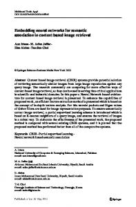
1. Introduction Typical digital systems consist of hardware components and/or software components executing on dedicated processors. The best performance can be typically achieved by a dedicated hardware solution, while a faster design and a less expensive solution are commonly achieved by software based solutions. Of course, a better tradeoff between flexibility, performance and cost is achievable if a co-design approach able to tune together the software and hardware components is followed [1][2][3][4][5]. Most hardware/software co-synthesis systems [6][7] target system architectures which consist of a generalpurpose processor, memory and application-specific hardware components (see Figure 1). According to the chosen technology and system complexity, the individual components may be implemented as individual ICs on a board or on a multi-chip module, or they can be integrated in the same integrated circuit. Actual VLSI integration complexities already allow for the integration of complex systems in the same integrated circuit and standard cell products with the capability to integrate complex megacells such as, memory, MPU (MicroProcessor Unit), MCU (MicroController Unit), multipliers and other advanced functions, are already available in the market. However, with NRE (Non Recurring Engineering) costs starting at around 100KECUs, these complex IC products are
well beyond the reach of the average customer and are therefore not suitable for low cost and/or low volume applications.
PROCESSOR
ASIC
MEMORY ASIC
Figure 1. Commonly targeted system architecture.
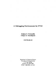
The environment proposed in this article targets low cost single chip solutions, enabled by the use of a fast turnaround sea -of-gates technology processed using direct -write laser based lithography [8][9], adequate for medium complexity applications where timing and area constraints are important.
PROCESSOR CORE
DATA MEMORY INTERFACE
WDT Timer units
PROGRAM MEMORY
FUNCTIONAL UNITS
I/O PORTS
Figure 2. Target system architecture of co-synthesis environment.
The targeted system architecture is illustrated in Figure 2. The processor core is instruction set compatible with a commercial microcontroller [10] in order to take advantage of existent and well understood standard development tools. The s ystem specification is therefore software based, with timing constraints directives included in the source code to guide the
XI Conference on Design of Integrated Circuits and Systems (DCIS'96), Sitges (Barcelona), November 19 -22, 1996, pp. 411 -416.
hardware/software partitioning. The functional units (FUs) using dedicated hardware are generated automatically by the co-synthesis environment when timing constraints are violated or functional parallelization is enforced by the designer.
2. The processor core The processor architecture targeted by the cosynthesis environment has been chosen to be instruction set compatible with a commercial microcontroller [10]. The major issues considered for the architecture selection are enumerated below:
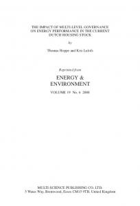
• All I/O ports can be implemented with 8 bits and are fully reconfigurable. A maximum of 8x8 bits I/O ports is currently allowed. Any register can be configured as an output-only port. • The number of register file registers is parameterized (with a current maximum of 80x8bit registers). If more than 32 registers are required a memory mapping scheme as described in [10] is used. Program Counter (F2) Program Memory up to 512 x 12 bits
8 bits 9-bits Stack
12 bits
• Core size not very large (8-bit wide datapath);
Register File (up to 80x8 bits registers)
Instruction Register
• Simple RISC (Reduced Instruction Set Computer) architecture (with a reduced orthogonal instruction set - 33 instructions 12 bit wide), in order to simplify the parameterization; • Good performance and code compactation [11] - all single cycle instructions except for program branches or when the target register is the program counter; • Compatibility with existent applications and development tools [11] (simulators, crossassemblers, emulators);
8 bits
MUX 5 bits FSR (F4)
RTCC (F1) Status (F3) Port B (F6) MUX Instruction decoder and Control MCLR
Port A (F5)
ALU
• A power down mode controlled by a sleep instruction for low power consumption;
RTCC/ WDTCLK
• One level of instruction pipelining (fetch of the next instruction in parallel with the execution of the actual instruction).
VDD, VSS
• Direct, indirect and relative addressing modes for data and instructions;
5 bits
Synchronizer WatchDog Timer
W
Timer
TRISA OPTION
OSC1 OSC2/CLKOUT Clock generation
8 bits TRISB
8 bits
• An internal Timer and WatchDog Timer (WDT); The processor core, designated by PISCPMS1[12], is based on the architecture shown in Figure 3. It has been completely specified in VHDL and mapped to a fast turnaround sea -of-gates technology using a commercial synthesis environment. Some of the characteristics of the implemented core are described below: • One instruction cycle (CLKOUT) is equivalent to 3 clock cycles (OSC1). • Control pipelining (introducing registers between the control and datapath section) has been added in order to have the actual cycle control signals in the beginning of clock (OSC1). • The GOTO and CALL instructions are executed in only one instruction cycle (3 clock cycles of OSC1).
1
Parameterized & Instruction Microcontroller for Sea-of-Gates.
S et
Compatible
PIC
Figure 3. Block diagram of the processor core achitecture.
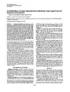
3. Co-Synthesis Environment The co-design system environment proposed is sketched in Figure 4. The system specification is currently defined by an assembler program compatible with existent commercial tools (for ex. MPALC [13] and MPSIM [14]). The system incorporates the PISCPMS core described in the previous section. The processor shares the internal bus with the functional units (see Figure 5). In order to maintain compatibility with existent development tools, the interface between the master processor and the hardware units extends the initial arquitecture, to allow parallel execution of the coprocessors, without requiring new specific instructions. For coordinating simulation and migration of the code segments to hardware, two technology files are
XI Conference on Design of Integrated Circuits and Systems (DCIS'96), Sitges (Barcelona), November 19 -22, 1996, pp. 411 -416.
Assembler program
MPALC (assembler)
Code segments with constraints extraction
ASM to ROM Converter
MPSIM (simulator)
Analysis of execution time
assembler
Number of registers necessary Library Functions
SYNTHESIS SYNTHESIS
Program Memory
VHDL sinthetizable
SYNTHESIS
Data Memory
Interface FUs
Gate Array
PISCPMS CORE
Figure 4. Co-Synthesis environment.
required: one contains the execution cycle number per instruction, the other contains information about the available gate-array chips (maximum gate complexity and number of pin signals in available packages). The migration to hardware and the core parameterization are automated. The parameterized core blocks are specified using parameterized VHDL descriptions which provide an efficient way for automatic block generation. The code segments which violate the performance constraints are migrated to hardware: the corresponding source code is translated to synthetizable VHDL and the hardware is synthesized by a commercial tool guid ed by scripts generated by the co -synthesis environment. The user specifies the performance constraints as directives added to assembler code (the syntax begins with a ‘;’ so that commercial assemblers consider the directives as comments). Six types of directives are currently supported by the system: • Time constraints directives: ;CONSTRAINT