A Comparison of Two Latency Insertion Methods in Dependent Sources Applications Ping Liu1, Jilin Tan2, Zhongyong Zhou1
José Schutt-Ainé, Patrick Goh
PCB System Division Cadence Design System, Inc 1 Shanghai, China, 2Chelmsford, MA USA
[email protected]
Department of Electrical and Computer Engineering University of Illinois at Urbana-Champaign Urbana, IL USA
[email protected]
Abstract— This paper compares two different formulations of the latency insertion method (LIM) for the analysis of circuits with dependent sources. One is the scalar LIM and the other is the amplification matrix LIM. Numerical experiments demonstrate that the scalar LIM necessitates much smaller time step than the amplification matrix LIM when handling certain types of dependent sources indicating better performance of the latter technique without a sacrifice in accuracy. Keywords-latency insertion methods(LIM); amplification matrix LIM; dependent sources
I.
scalar
LIM;
INTRODUCTION
With the increase in circuit density and I/O pin count in high-speed circuit systems, the simulation of large circuits such as power distribution networks (PDN) has become a serious challenge in the computer-aided design of the chippackage-board circuits. The latency insertion method (LIM) [1] has recently emerged as an efficient time-domain simulator for large-scaled networks. The method uses reactive latency in all branches and nodes of a circuit to generate update algorithms for the voltage and current quantities. The updating of branch currents and node voltages is performed in a leapfrog manner similar to the Yee algorithm used in the Finite-Difference Time-Domain (FDTD) method [2]. As a result, LIM has linear computational complexity and is thus substantially faster than the traditional matrix-vector product based methods such as SPICE[3]. In a chip-package-board network, non-linear devices represented by IBIS models are commonly encountered during simultaneous switching noise (SSN) analysis. IBIS models essentially consist of dependent sources and lumped RLGC circuits. Thus, simulation of dependent sources is very important in SSN analysis. Currently, two different types of LIM formulations exist for this analysis. One is the conventional LIM introduced in [1] and referred to as the scalar LIM, and the other is the amplification matrix LIM which was first presented in [4]. Both LIMs can support dependent source simulation. In this paper, we compare the two LIM algorithms and their efficiency in dealing with circuits containing dependent sources. The equations and the stability conditions of the explicit (forward Euler), semiimplicit (central difference) and fully-implicit (backward Euler) formula of the two LIMs are all presented and compared.
978-1-4244-9399-9/11/$26.00©2011 IEEE 978-1-4244-9401-9/11/$26.00©2011
SCALAR LIM
II.
295
LIM can analyse any arbitrary network in which one can define a branch as a connection between two nodes (excluding the ground reference node) through Thévenin and Norton transformations. Figure 1 shows a branch connecting nodes i and j has a resistor, an inductor and a voltage source in series. Node i combines a conductance, a capacitor and a current source in parallel. In the network, each branch must contain an inductance and each node must provide a capacitance path to ground. Otherwise, a small inductor or a small shunt capacitor should be inserted into the branch or connected to the node.
Figure 1. Normal linear branch and node
In order to solve the node voltages and the branch currents, LIM discretizes the time variables. There are three difference schemes which have different stability conditions. [5] In the standard LIM algorithm [1], the time-domain discrete equations for the linear elements in a branch linked a node are as follows. In the formulations, n represents the nth time step and Δt is the duration of one time step. A. Explicit (Forward Euler)
⎛ Rij Δt ⎞ n Δt n +1 / 2 ⎟ I ij + I ijn +1 = ⎜1 − Vi − V jn +1 / 2 + E ijn +1 / 2 ⎜ ⎟ L L ij ij ⎝ ⎠
(
⎛ ΔtGi Vi n +1 / 2 = ⎜⎜1 − Ci ⎝
Mi ⎞ n−1 / 2 Δt ⎟⎟Vi − ( H in − ∑ I ikn) Ci k =1 ⎠
)
(1)
(2)
In the explicit case, the resistor term RI is given by RI n
and the conductance term GV is given by GV n −1/2 . This is a first-order accurate scheme. It has stricter stability properties than FDTD. If the conductance G = 0 , its stability condition is Δt ≤ LC ⎡ N 2 + 1 − N ⎤ , ⎣ ⎦
N=
R C 4 L
(3)
B. Semi-Implicit (Central Difference)
M qp = − 1 if branch p is incident at node q and the current flows into node q. M qp = 0 if branch p is not incident at node q.
−1
⎤ ⎛ Lij Rij ⎞ ⎡⎛ Lij Rij ⎞ I ijn +1 = ⎜ + ⎟ ⎢⎜ − ⎟ I ijn + Eijn +1/2 + Vi n +1/2 − V jn +1/2 ⎥ (4) ⎝ Δt 2 ⎠ ⎣⎝ Δt 2 ⎠ ⎦
Explicit and fully implicit algorithms can be obtained in a similar manner. One advantage of the amplification matrix LIM lies in its ability to accurately predict the time step ensuring the stability. To see this, we combine Eq. (10) and (11) together in a block matrix form and assume the sources are zero as follows:
−1
Mi ⎤ ⎛ C G ⎞ ⎡⎛ C G ⎞ (5) Vi = ⎜ i + i ⎟ ⎢⎜ i − i ⎟Vi n −1/2 − H in − ∑ I ikn ⎥ ⎝ Δt 2 ⎠ ⎣⎝ Δt 2 ⎠ k =1 ⎦ In the semi-implicit case, the resistor term RI is given by R ( I n + I n +1 ) / 2 and the conductance term GV is given by G (V n −1/ 2 + V n +1/ 2 ) / 2 . This is a second-order accurate scheme. It has the same stability properties as FDTD. If the conductance G = 0 , its stability condition becomes (6) Δt ≤ LC n +1/2
G G ⎡v n+1/2 ⎤ ⎡v n−1/2 ⎤ A = G ⎢ n+1 ⎥ [ ] ⎢ G n ⎥ ⎣i ⎦ ⎣ i ⎦
where ⎡
[ A] = ⎢
C. Fully Implicit (Backward Euler) −1
⎛ R Δt ⎞ ⎡ ⎤ Δt I ijn+1 = ⎜1 + ij ⎟ ⎢ Iijn + (Vi n+1/2 − V jn+1/2 + Eijn+1/2 ) ⎥ ⎜ ⎟ L L ⎥⎦ ij ⎠ ⎢ ij ⎝ ⎣ −1
(7)
N=
R C 4 L
⎛ [ L] [ R ] ⎞ Q+ = ⎜ + ⎟ 2 ⎠ ⎝ Δt
(9)
IV.
−1
G ⎤ ⎛ [C ] [G ] ⎞ ⎡⎛ [C ] [G ] ⎞ G n −1/ 2 G n G v n +1/2 = ⎜ + − + h −[M ]i n ⎥ ⎟ ⎢⎜ ⎟v 2 ⎠ ⎣⎢⎝ Δt 2 ⎠ ⎝ Δt ⎦⎥
Q Q − Q [M ] +
−
T
+
⎤ ⎥ P [ M ]⎥⎦
(13)
+
−1
⎛ [C ] [G ] ⎞ P− = ⎜ − ⎟ 2 ⎠ ⎝ Δt
−1
−1
(14a)
⎛ [ L] [ R ] ⎞ Q− = ⎜ − ⎟ 2 ⎠ ⎝ Δt
(14b)
TWO LIMS IN HANDLING DEPENDENT SOURCES
The scalar LIM and the amplification matrix LIM have some difference in handling the circuits with dependent sources. The difference lies on the updating equations. It is small but can cause large difference in performance of the two methods. To clarify this point, consider a simple circuit as example in which the fully implicit LIM is used for convenience.
If the current and voltage variables in Section II are written in a vector-matrix formulation, the scalar LIM becomes the amplification matrix LIM. Let us take the semi-implicit scalar LIM for example. Equation (4) and (5) can be written in a vector-matrix formulation as: −1
−
[A] is called the amplification matrix since the voltages and the currents in the network will be amplified by [A] at each time step in the absence of sources. Therefore, to keep the simulation stable, the time step Δt should be chosen such that all the eigenvalues of the amplification matrix have magnitudes strictly less than 1. [6][9]
AMPLIFICATION MATRIX LIM
G ⎤ ⎛ [ L ] [ R ] ⎞ ⎡⎛ [ L ] [ R ] ⎞ G n G n +1/ 2 T G i n +1 = ⎜ + − + [ M ] v n +1/ 2 ⎥ ⎟ ⎢⎜ ⎟i + e 2 ⎠ ⎣⎢⎝ Δt 2 ⎠ ⎝ Δt ⎦⎥
+
⎛ [C ] [G ] ⎞ + P+ = ⎜ ⎟ 2 ⎠ ⎝ Δt
The scalar LIM simulation is done by alternate “leapfrog” updates of branch-currents and node-voltages in the time domain according to the current and voltage equations.
III.
T
+
in which we have defined
⎤ ⎛C ⎞ ⎡C (8) = ⎜ i + Gi ⎟ ⎢ i Vi n −1 / 2 − H in − ∑ I ikn ⎥ Vi Δ Δ t t ⎝ ⎠ ⎣ k =1 ⎦ In the fully implicit case, the resistive term RI is given by n +1/2 . This RI n +1 and the conductance term GV is given by GV has first-order accuracy. It has the more relaxed stability than FDTD. If the conductance G = 0 , its stability condition is Δt ≤ LC ⎡ N 2 + 1 + N ⎤ , ⎣ ⎦
−P+ [M ]
P+ P−
⎢⎣Q [ M ] P P
Mi
n +1 / 2
(12)
(10) (11)
Figure 2. A circuit including a VCCS dependent source
Figure 2 shows a circuit including a voltage controlled current source (VCCS). Using the scalar LIM, we can create the node voltage and the branch current equations (15).
G i n +1 is the branch current vector (dimension Nb ) G representing the currents at branches at time n + 1 , and v n +1/ 2 is the node voltage vector (dimension N n ) representing the voltages at the nodes at time n + 1 / 2 . [R] and [L] are the resistance and inductance matrices with dimension Nb by Nb respectively. [G] and [C] are the conductance and capacitance matrices with dimension N n by N n respectively. [M] is the N n × N b incidence matrix defined as follows M qp = 1 if branch p is incident at node q and the current
(
n I vccs = g ⋅ V1n+1/2 − V2 n+1/2
)
(15)
−1
V1n +1/2
⎤ ⎛C ⎞ ⎡C = ⎜ 1 + G1 ⎟ ⎢ 1 V1n −1/2 − I n ⎥ ⎝ Δt ⎠ ⎣ Δt ⎦ −1
⎛C ⎞ ⎡C ⎤ n V2 n+1/2 = ⎜ 2 + G2 ⎟ ⎢ 2 V2n −1/2 − − I n + I vccs ⎥ t t Δ Δ ⎝ ⎠ ⎣ ⎦
(
)
Obviously there is a paradox in the above equations. The controlled current at time n depends on the node voltage at time n+1/2. However the node voltage at time n+1/2 also depends on the controlled current at time n. The scalar LIM
flows away from node q.
296
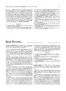
-TijkVk: Vk is the controlling voltage of node k.
cannot implement the closed loop in Eq(15). The solution is to n n−1 in the replace I vccs by Ivccs V2n +1/ 2 update equations. The above equations then become
(
n −1 I vccs = g ⋅ V1n +1/2 − V2 n −1/ 2
)
-WijmnEmn:the controlling voltage Emn is an independent voltage source in a branch.
(16)
•
−1
n +1/2 1
V
⎤ ⎛C ⎞ ⎡C = ⎜ 1 + G1 ⎟ ⎢ 1 V1n −1/2 − I n ⎥ Δ t Δ t ⎝ ⎠ ⎣ ⎦ −1
-ZijpqIpq: Ipq is the controlling current of branch pq.
⎛C ⎞ ⎡C n −1 ⎤ V2 n +1/2 = ⎜ 2 + G2 ⎟ ⎢ 2 V2n −1/2 − − I n + I vccs ⎥ t t Δ Δ ⎝ ⎠ ⎣ ⎦
(
)
Eq.(16) introduces an approximation which leads to a decrease in accuracy. The problem in Eq.(15) can be easily solved by the amplification matrix LIM without any approximation. Eq. (15) can be rewritten into a block matrix form as follows: ⎛ V1 ⎞ ⎜ ⎟ ⎝ V2 ⎠
n+
1 2
1 ⎛ ⎜ 1 + ΔtC1−1G1 =⎜ ⎜ −ΔtC2−1 g ⎜ −1 ⎜ (1 + ΔtC2 ( G2 − g ) )(1 + ΔtC1−1G1 ) ⎝
⎞ 1 ⎟ n− ⎟ ⎛ V1 ⎞ 2 ⎜ ⎟ ⎟ ⎝ V2 ⎠ 1 ⎟ (1 + ΔtC2−1 ( G2 − g ) ) ⎟⎠ 0
Branch capacitance Cij; inductance Lij; resistance Rij
•
Independent voltage source Eij
•
Independent current source Hmn
Figure 4.
The block matrix formulation in semi-implicit LIM is
⎛ P+ P− A' = ⎜ ⎜ Q M T ' P+ P− ⎝ +
T
⎛ L R' ⎞ Q+ = ⎜ + ⎟ ⎜ Δt 2 ⎟ ⎝ ⎠
−1
⎛ C G' ⎞ P+ = ⎜ + ⎟ ⎜ Δt 2 ⎟ ⎝ ⎠
−1
⎛ L R' −1 ⎞ Q− = ⎜ − − Δt ⋅ CN ⎟ ⎜ Δt 2 ⎟ ⎝ ⎠
T
G' = G − B M ' = M − S
U'= E +U
Some restrictions apply in the use of dependent sources for the amplification matrix LIM, namely: • The controlling sources and the controlled sources must be in the same block; • The controlling current cannot be the current through an element(Gi /Ci /Li /Ei) at a node; • If the controlled voltage source is at a node, it should be transformed into a controlled current source with a very small resistance inserted by a Norton transformation. • If the controlled current source is in a branch, it should be changed to a controlled voltage source with a very large resistance using a Thévenin transformation.
- BikVk: Vk is the controlling voltage at node k. current controlled current source(CCCS) : -SipIp: Ip is the controlling current of branch p; -UijHj: the controlling current Hj is an independent current source at a node. Independent current source Hi
(18)
R' = R − Z M ' = M + T W ' = E + W
Fig. 3 shows a node i’s topology including • voltage controlled current source(VCCS) :
•
⎞ ⎟ Q + Q − − Q + M T ' P + M ' ⎟⎠ −P+ M '
⎛ C G' −1 ⎞ P − = ⎜ − − Δt ⋅ LN ⎟ ⎜ Δt 2 ⎟ ⎝ ⎠
Figure 3. General node topology with dependent sources
Node inductance Li ; conductance Gi; capacitance Ci
JJJG 1 ⎞ ⎛V n− 2 ⎞ ⎟ ⎟ ⎜ CN ⎜ JJJG n −1 ⎟ ⎟ Q + M T ' P + ⎟⎠ ⎜ I L ⎝ N ⎠ P+
where
Eqs (15) and (17) are entirely equivalent. However the scalar LIM cannot implement Eq. (15) without sacrificing the accuracy due to the closed loop. The amplification matrix LIM can implement Eq.(17) accurately. For generality, the amplification matrix LIM formulations for general node and branch circuits including dependent sources are presented.
•
General branch topology with dependent sources
1 ⎛ JG n + 12 ⎞ ⎛ JG n − 12 ⎞ ⎛ ⎞ ⎛ JG n + 2 ⎞ ⎛ 0 P+U ' ⎜V ⎟ = A ' ⎜ V ⎟ + ⎜ 0 ⎟⎜ E ⎟ − ⎜ G G JJ G 1 ⎜ n+ ⎟ ⎜ n ⎟ ⎜ T ⎟⎜ n ⎟ ⎜ ⎝I ⎠ ⎝ I ⎠ ⎝ Q +W ' Q+ M ' P+ U ' ⎠ ⎝ H ⎠ ⎝ Q +
⎛ ⎞ −ΔtC ⎜ ⎟ 1 + ΔtC G ⎜ ⎟In + ⎜ ⎡ ΔtC2−1 g ⋅ ΔtC1−1 ⎤ ⎟ ⎜ ⎟ ⎜ 1 + ΔtC −1 ( G − g ) ⎢1 + 1 + ΔtC −1G ⎥ ⎟ ⎣ 2 2 1 1 ⎦⎠ ⎝
•
•
(17)
−1 1 −1 1 1
•
current controlled voltage source(CCVS) :
We can use the new amplification matrix A ' to predict the stability of a time step Δt in the presence of dependent sources. V.
EXAMPLE
In this section we use a real case to compare the performance between the two LIMs in handling circuits with dependent sources. Fig. 5 shows a circuit including a voltage controlled voltage source (VCVS). The controlling coefficient e is 1.1. Since the controlled voltage source is at a node, it should be transformed into a controlled current source by the
Independent voltage source Ei
Fig. 4 shows the topology of a branch between node i and j including • voltage controlled voltage source(VCVS) :
297
Norton transformation. The circuit after transformation is shown in Fig.6. The inserted small resistor is 0.001 Ω.
In the Semi-implicit formulation and the Backward Euler formulation, when dependent sources are present, the voltage at a node depends on the voltage at a different node at the same time step. That is a closed loop, so in the scalar LIM, we use the values at the previous time step to replace those at the current time step as shown in the rectangular frames as follows. A. Explicit (Forward Euler)
Figure 5. A circuit with a VCVS
Mi ⎛ V n +1/ 2 − Vi n −1/ 2 ⎞ n −1/2 Ci ⎜ i − H in + I Lin − BikVkn −1/ 2 − Sip I pn = −∑ I ijn ⎟ + GiVi Δt j =1 ⎝ ⎠ (19)
B. Semi-Implicit (Central Difference) ⎛ V n +1/2 − Vi n −1/2 ⎞ Gi n+1/ 2 + Vi n −1/2 ) − H in Ci ⎜ i ⎟ + (Vi Δt ⎝ ⎠ 2 Mi B + I Lin − ik (Vkn +1/2 + Vkn−1/2 ) − Sip I pn = −∑ I ijn 2 j =1
Figure 6. An equivalent circuit of the VCVS circuit
Table I is a maximum time step comparison between the scalar LIM and the Amplification-matrix LIM. The time step of the scalar LIM is obtained experimentally. The time step of the Amplification-matrix LIM can be predicted by the new amplification matrix A ' in Eq. (18). The update formulation we used in the scalar LIM is in the appendix. It is obvious the Amplification Matrix LIM can use much larger time-step if the semi-implicit formula or the backward Euler formula is adopted. Taking the semi-implicit LIM for example, the timestep of the scalar LIM is 3e-15 seconds while that of the amplification matrix LIM is 4e-11 seconds. Therefore, if the circuit includes dependent sources, it is best to use the amplification matrix LIM rather than the scalar LIM because the former has thousands of times higher performance than the latter. TABLE I.
Time-step (seconds)
Scalar LIM Amplification Matrix LIM
Mi
− H in + I Lin − BikVkn −1/2 − Sip I pn = −∑ I ijn j =1
( Forward Euler) 1.9e-15 1.9e-15 VI.
(21)
C. Fully Implicit (Backward Euler) Mi ⎛ V n+1/2 − Vi n −1/2 ⎞ n +1/ 2 Ci ⎜ i − H in + I Lin − BikVkn+1/ 2 − Sip I pn = −∑ I ijn ⎟ + GV i i Δt j =1 ⎝ ⎠ (22) Mi ⎛ Vi n +1/2 − Vi n −1/2 ⎞ n +1/ 2 − H in + I Lin − BikVkn −1/ 2 − Sip I pn = −∑ I inj Ci ⎜ ⎟ + GV i i Δt j =1 ⎝ ⎠
(23)
REFERENCES [1]
Jose E. Schutt-Ainé, “Latency insertion method (LIM) for the fast transient simulation of large networks,” IEEE Trans. on Circuits and Systems — I: Fundamental Theory and Applications, vol.48, no.1, pp81-89, Jan. 2001.
[2]
K. S. Yee, “Numerical solution of initial boundary value problems involving Maxwell’s equations in isotropic media,” IEEE Trans. Antennas Propagat., vol. 14, pp. 302-307, May 1966.
MAXIMUM TIME STEP COMPARISON
Explicit
(20)
⎛ V n +1/2 − Vi n −1/ 2 ⎞ Gi n +1/ 2 Ci ⎜ i + Vi n −1/ 2 ) ⎟ + (Vi t Δ 2 ⎝ ⎠
Semiimplicit (Central Difference)
Fully Implicit (Backward Euler)
[3]
L.W.Nagel, “SPICE2, A Computer program to simulate semiconductor circuits,” Univ. California, Berkeley, Tech. Rep. ERL-M520, 1975.
[4]
3e-15 4e-11
4e-14 1e-10
Jose E. Schutt- Ainé, “Stability analysis of the latency insertion method using a block matrix formulation,” in EDAPS’08, Seoul, Korea, 2008, pp. 155-158.
[5]
Zhichao Deng and Jose E. Schutt-Ainé, “Stability analysis of latency insertion method (LIM),” in EPEP’04, Oregon, Poland, 2004, pp.167170.
[6]
Patrick Goh, Jose E. Schutt-Ainé, etc., “Partitioned latency insertion method (PLIM) with stability considerations,” in SPI’11, Naples, Italy, 2011, pp. 107-110.
[7]
Patrick Goh, Jose E. Schutt-Ainé, etc., “Partitioned latency insertion method (PLIM) with a generalized stability criteria,” IEEE Trans. on Advanced Packaging, to be published.
[8]
D. Klokotov and J. E. Schutt-Ainé, “Transient simulation of lossy interconnects using the Latency Insertion Method (LIM),” in Proc. IEEE (EPEP 2008), San Jose, CA, Oct. 2008, pp.251-254.
[9]
J.P.Hespanha, Linear Systems Theory. Princeton, NJ: Princeton University Press, 2009.
CONCLUSION
The conventional scalar LIM and the amplification matrix LIM were compared in terms of stability conditions. Their formulations and performances in handling circuits with dependent sources were also compared. This study shows that the amplification matrix LIM is superior by several orders of magnitude than the scalar matrix LIM and is a better option for circuits with dependent sources. APPENDIX Scalar method formulations for dependent source applications
298