In: Proceedings of the International Conferences on Software Engineering Research and Practice 2003, Volume I, Las Vegas, NV, June 2003, pp. 398-404.
3CoFramework: A Component-based Framework for Distributed Applications ∗ Shifeng Zhang Computer Science & Engineering University of Nebraska-Lincoln Lincoln, Nebraska 68588-0115, U.S.A
[email protected]
Abstract The software engineering community has introduced component and connector concepts to support architecture-based software descriptions. However, there still exists a gap in transitioning component and connector concepts from the design level to the implementation level. This paper proposes a framework which can implement components and connectors based on the separation of three types of meta-information of a component: interface information, composition information, and instance information. With the proposed framework, architects and developers can get a clear architectural view of a component-based distributed application, and flexibly implement and maintain it. The National Agricultural Decision Support System (NADSS), a component-based distributed decision support system, is discussed as a case study to illustrate the framework.
Keywords: component, connector, coordinator, framework, software architecture
1
Introduction
The software engineering community has introduced component and connector concepts to support architecturebased software descriptions: a component represents an independent computational unit; a connector represents an interaction among a set of components [1]. Architecture Description Languages (ADLs) were proposed, as modelling notations based on component and connector concepts, to support architecture-based development. Example ADLs include ACME [7], C2 [10], Darwin [9], Unicon [13], and Wright [3]. Though ADLs provide semantic notation and formal analysis based on component and connector concepts, few ADLs provide the corresponding implementation for such concepts, and little support for the dynamic architecture. On the other hand, existing Interface Definition ∗ This work was supported, in part, by a grant from the NSF (EIA-0091530) and a cooperative agreement with USDA FCIC/RMA (2IE08310228).
Steve Goddard Computer Science & Engineering University of Nebraska-Lincoln Lincoln, Nebraska 68588-0115, U.S.A
[email protected]
Languages (IDLs) have been extended to contain more architectural and composition information at the implementation level. Example extended IDLs include Scientific-IDL (SIDL) [4] and Component-IDL (CIDL) [11]. However, component frameworks with extended IDLs do not view the connector as a first class entity at the implementation level. Rather, they distribute the connection information to the components without support for connectors. Viewing component-based software as a collection of components and connectors is important at both the design level and the implementation level. However, there still exists a gap in transitioning component and connector concepts from the design level to the implementation level. In this paper, a framework, separating components and connectors at the implementation level, is proposed. The proposed framework consists of three major roles: the component, the connector, and the coordinator, corresponding to the three types of meta-information for a component: interface information, composition information, and instance information. We call the framework 3CoFramework. The component implements computational logic functions, the connector combines different components or connectors to create new computational logic functions, and the coordinator manages instances of components and connectors by collecting their non-functional property information at run-time. The connector and the coordinator are viewed as first class entities with the component. Our proposed framework can be applied in componentbased applications. The National Agricultural Decision Support System (NADSS) is a component-based distributed application built on a layered architecture from our earlier work [8]. This paper, as an example, applies the 3CoFramework to the NADSS. The rest of this paper first discusses related research in software architecture and software composition in Section 2, and then presents the conceptual view of the proposed framework in Section 3. Section 4 describes an implementation view of the proposed framework based on CORBA middleware. Section 5 presents the layered NADSS archi-
In: Proceedings of the International Conferences on Software Engineering Research and Practice 2003, Volume I, Las Vegas, NV, June 2003, pp. 398-404.
tecture and how to apply the proposed framework to it. We introduce our future work in Section 6 and conclude in Section 7.
2
are as follows. First, localizing composition information in the run-time entity can eliminate the loss of design information. It is especially useful for reverse engineering the application. Second, the component implementation independent of composition information makes the component more reusable. Third, the separation of the components and connectors at the implementation level makes the application evolvable; new components or connectors can be added with less impact on existing components and connectors. The 3CoFramework separates components and connectors at the implement level. We observed that there are three types of meta-information related to a component: interface information, instance information, and composition information. Interface information describes the programmable interface of a component. Instance information describes component non-functional property information at run-time. Examples of non-functional property information include reference and security information. Composition information describes cooperative relationships with other components and connectors needed to implement new computational logic functions. Both the instance information and composition information may change at run-time or maintenance-time. The separation of these three types of meta-information at the implementation level makes the development clear and flexible. It is also natural to find that the meta-information has a direct linkage to component and connector concepts introduced at the design level. In the 3CoFramework there are three major roles corresponding to the three types of meta-information. The connector is used to separate the composition information from the interface information; the coordinator is used to separate the instance information from the interface information and composition information; the component is independent of the composition information and instance information. Further, we believe ADLs, which can describe both the static architecture and the dynamic architecture, are necessary for the 3CoFrameWork. Section 6.1 introduces our on-going work on an XML-based ADL.
Background and related work
2.1. ADLs and extended IDLs Architecture Description Languages, such as ACME, C2, Darwin, Unicon, and Wright, were proposed to provide the formal description of the architecture and component interaction. Most ADLs separate the connector from the computational component; however, they have limited support for the component and connector at the implementation level, and the dynamic architecture at run-time [2]. ACME and Wright are used strictly as modeling notations though Wright can also provide formal analysis [7,1]. Darwin uses implicit connections, which are distributed in the components without support for the connector [9]. Unicon provides compilers only for pre-built connectors [13]. C2 does better with the ArchStudio tool, an architecture-based software development environment [10]. Though C2 only supports a particular architecture style, the C2 architectural style, we consider it a good example in transferring component and connector concepts from the design level to the implementation level. However, as a research prototype, C2 is still under experimental “alpha” state and has less support for real applications. Existing Interface Definition Languages (IDLs) lack support for components. The CORBA Component Model (CCM) from OMG, known as CORBA Specification 3.0, adds new elements to the IDL, which make it componentaware as a Component IDL (CIDL). The Scientific IDL (SIDL) is another similar specification that extends the CORBA IDL to the scientific computing environments. Component frameworks with extended IDLs, like CIDL and SIDL, can implement applications with composite components. However, the components combine the interface information and composition information together with provided and required interfaces. There does not exist a role like connector, and the composition information is distributed to the components. This interaction enforces an asymmetric model of interaction, which implies the connection is not independent of the component that provides it. A couple of weaknesses follow from such a model: the connection may change when the system evolves; the computation modules may be reused in other systems with different connection relations [5].
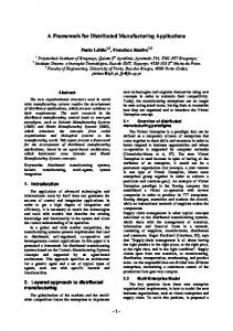
3 3CoFramework conceptual view The 3CoFramework consists of the component, the connector and the coordinator. They correspond to the three types of meta-information for a component: interface information, composition information, and instance information. Figure 1 shows the relationship between the three elements. The component and the connector should register themselves with the coordinator when instantiated. The connector depends on the instantiated components and connectors to process the interaction. The coordinator provides the most suitable components’ or connectors’ reference information to the connector at run-time.
2.2. 3CoFramework Viewing software architecture as a collection of components and connectors is important at both the design level and the implementation level. The advantages of separating components and connectors at the implementation level 2
them by either recontacting the coordinator or terminating the process. Such errors should be transparent to the endusers. d) Self-registered function: The connector performs the same registration function with the coordinator as the component. Section 4.2 gives one example of the connector definition.
Componet
Registration
Dependencies Registration
Coordinator
Support
Connector
3.3. Coordinator
The relationship between the component, the connector and the coordinator. Figure 1.
The coordinator integrates and manages the component and connector at run-time. It has two functions: a) Component and connector information collection: The coordinator collects the instantiated components’ and connectors’ non-functional property information with their registration functions. b) Merit-based component and connector selection: The connector knows its desired components or connectors type, not their reference information at compile-time; it depends on the coordinator to provide the most suitable instantiated components or connectors at run-time. The coordinator provides algorithms to find the most suitable component or connector based on collected information. The coordinator can play either a decentralized or a centralized role in the 3CoFramework, depending on the application scale and complexity. If there are many components and connectors, which are located in different domains, decentralized coordinators are preferred for each domain. In such applications, based on the domain policy, coordinators cooperate together to collect, exchange and share the instantiated component and connector information. With small scale or single domain applications, a centralized coordinator can simplify the design and implementation. The naming conflict problem can also be prevented. Section 4.3 gives one example of the coordinator definition.
3.1 Component A component is an independent computational unit at a higher level than an object, and it is the composite unit in a software application. A component in the 3CoFramework does not contain any composition information, and it can engage in any related interaction. Below are its two functions: a) Computation logic implementation: A component implements the computational logic with exposed interfaces. b) Self-registered function: A component has nonfunctional property information in addition to its computational interface, such as reference information, access control information, mean execution time and execution time variance information. In the 3CoFramewrok, the component must register itself, with those information elements, to the coordinator once it is instantiated. Section 4.1 gives one example of the component definition.
3.2. Connector The connector in the 3CoFramework is based on the definition from [14]: “Connectors mediate interactions among components; that is, they establish the rules that govern component interaction and specify any auxiliary mechanisms required.” The above definition indicates that the most important function of a connector is to mediate the interaction among components. It leaves the unclear meaning of “any auxiliary mechanisms required”. In the 3CoFramework, at least two mechanisms are considered to be required for the connector. One is the adaptation of the interaction among incompatible components. The other is the exception handler. A connector in the 3CoFramework has the following four functions: a) Control link: The connector specifies interaction among components. b) Data format conversion: The connector converts the incompatible transferred data among components. c) Fault tolerance: In a distributed environment, the coordinator may provide outdated component property information to the connector. For example, the desired components do not exist because of hosts rebooting or processes crashing. When such errors occur, the connector needs to handle
4 3CoFramework implementation views This section provides one implementation view based on CORBA middleware. There are several reasons to separate the conceptual view from the implementation view in the 3CoFramework. First, the conceptual view is more general than the implementation view at a high level. For example, the coordinator can be implemented as either centralized or decentralized in the implementation view. Second, the conceptual view can be built on the top of different distributed computing platforms, such as CORBA, DCOM, or Java RMI. Third, different accessory entities can be added to the implementation, which makes the implementation more flexible. In the following implementation view based on CORBA middleware, object interaction are the concern of an Object Request Broker (ORB), while the concerns of 3
organizing a set of distributed objects into a manageable framework are dealt with by the 3CoFramework.
Like the component, the connector also follows the factory pattern. The connector factory also needs to register itself with the coordinator. In addition to that, a connector has an attribute rule to define the involved components and connectors. However, a rule does not have run-time reference information about the desired components and connectors. The connector needs to get such information from the coordinator at run-time. With the operation findAppImplementChain(), provided by coordinator, the returned information from the coordinator contains the desired component and connector reference information. The operation composition() directs the operation invocation sequences, maps the data conversion, and handles exceptions among components. Unfortunately, CORBA IDL can not give detailed information on the interactive relationship among components. A new XML-based ADL is under development in our work, which can provide a gray box view instead of the current black box view.
4.1. Component The component is implemented as a CORBA object. All components in the 3CoFramework are derived from the below component interface definition. interface AppServer; interface AppServerFactory{ attribute RegisterInfo whataboutme; attribute long number; boolean RegisterMyself(in string ior); }; interface AppServer{ void destroy(); }; interface AbstractComponent : AppServer { };
Components in 3CoFramework follow the factory pattern. As a daemon, a factory object occupies less resource than its created objects; second, flexible objects can be created from the factory object given the different parameters for a creation function. There is a structure RegisterInfo to describe the factory of the component. For example, one field repositoryID in the RegisterInfo , which is similar to the repository ID in CORBA [11], is used to identify the component’s factory. Since the 3CoFramework is an open framework, there exists a naming conflict problem; repositoryID provides a unique identifier for the component’s factory to avoid naming conflicts at large. Another field Description in the RegisterInfo describes the component’s computation functionality. The operation RegisterMyself() is used to register the component’s factory with the coordinator. The coordinator’s reference information is assumed to be well-known to component factories.
4.3. Coordinator A centralized coordinator is presented with the coordinator interface definition as follows. interface AbstractorCoordinator{ readonly attribute RegisterInfoSeq registeredAppFactory; readonly attribute CORBAServerDescSeq registeredAppFactoryType; long addAppServerInfo( in RegisterInfo updateinfo); long rmAppServerInfo( in RegisterInfo updateinfo); RegisterInfoSeq findAppImplementChain( in CORBAServerDescSeq request); };
The operation addAppServerInfo() receives registration information from instantiated component and connector factories while the operation rmAppServerInfo() unregisters the instantiated component and connector factories. The operation findAppImplementChain() chooses the most suitable component or connector factories based on their nonfunctional property information and other useful information provided during registration (see Section 4.4.2). The algorithm to choose the most suitable component or connector factories, however, is not specified here. The coordinator location information is assumed to be well-known in the 3CoFramework.
4.2. Connector The connector mediates interaction among components. In CORBA, there are two methods to invoke the operations on CORBA objects: static invocation and dynamic invocation [11]. Dynamic invocation method is prefered in this implementation. It allows the connector implementation to be independent of the components’ interfaces. Below is the interface definition for connector. interface AppServer; interface AppServerFactory{ attribute RegisterInfo whataboutme; attribute long number; boolean RegisterMyself(in string ior); }; interface AppServer{ void destroy(); }; interface AbstractConnector : AppServer { readonly attribute CORBAServerDescSeq rule; ParameterSeq composition(in ParameterSeq psin); };
4.4. Accessory roles The roles in this section are not necessary in the 3CoFramework. However, the 3CoFramework is more flexible with them. The ClientBroker is a broker for clients to access components and connectors in the 3CoFramework. The NodeResourceManager (NRM) provides a node’s state information (the node is the machine from which the component or connector is instantiated) to the coordinator, which 4
4.5. Cooperation in the 3CoFramework implementation view
can then help the coordinator choose the most suitable component or connector. 4.4.1
Figure 2 describes the relationship among the coordinator, component factories, connector factories, the ClientBroker, and NRMs: 1. The client submits a request to the ClientBroker; 2. Based on the client’s request, the ClientBroker asks the coordinator for the suitable component or connector factory. If required, the ClientBroker will authenticate the clients; 3. Based on collected non-functional property information and node performance information, the coordinator chooses the most suitable component or connector factory for the ClientBroker; 4. The ClientBroker returns the chosen component or connector factory reference to the client; 5. The client calls the chosen component or connector factory to create a new component or connector and process the service. The component or connector processes the request; if it is connector, it will call the coordinator to get the most suitable component or connector; 6. The client receives the final result from the component or connector.
Client broker
The client uses the ClientBroker to ask the coordinator for the most suitable component or connector, and then accesses the component or connector. The ClientBroker is also useful for user access control; it allows only authorized clients to access the provided services. The ClientBroker can be implemented as part of the coordinator. To make the framework clear, it is separated as an independent role in the implementation view. Below is the ClientBroker’s interface definition. interface ClientBroker { // client ask for all service information CORBAServerDescSeq getServicesInfor(); // client ask for desired component // and connector RegisterInfo askforService(in CORBAServerDesc ri); // client authentication boolean authentication(in string); };
Clients can get all registered component or connector factory information from the coordinator through operation getServicesInfor(); to get the access information from a desired component or connector factory, clients call the operation askforService(). 4.4.2
NODE
NRM Component factory Client
6 Connector factory
5 1
Node resource manager (NRM)
NRM Component factory
ClientBroker 3 2
The non-functional property information from the component and connector will not be enough to choose the most suitable component and connector. The performance of the component and connector depends largely on the nodes’ computing performance information. A NRM service can be added to each node in the 3CoFramework. It collects the state information of the host, including the CPU load time, available disk space, etc. This information is then sent to the coordinator. The NRM interface is shown below.
NODE
4
Center−oriented Coordinator
Component factory
NODE
NRM Component, Connector, NRM registration
Connector factory
Sequence call between client and server
Component factory
Roles cooperation in the 3CoFramework. To simplify the figure, the procedure by which the chosen connector asks the coordinator to retrieve the most suitable instantiated components or connectors is not illustrated. Figure 2.
interface NodeResourceManager { readonly attribute HostDesc hostinfo; };
5 NADSS: a case study
With the NRM, the coordinator needs to add the following registration, un-registration, and update functions:
5.1. Introduction to NADSS interface Coordinator:AbstractCoordinator{ long registerNodeResourceManager( in NodeResourceManagerInfo self); long unregisterNodeResourceManager( in NodeResourceManagerInfo self ); long updateNodeResourceManagerHostInfo(in NodeResourceManagerInfo self); };
NADSS is being developed for the Risk Management Agency of the USDA. The initial focus of the NADSS project is to improve the quality and accessibility of drought related knowledge, information, and spatial analysis for drought risk management. A 4-layer architecture has been built for NADSS [8]. The 3CoFramework is applied to the 5
4-layer NADSS architecture based on the follow considerations: 1. NADSS has dynamic development and composition requirements throughout its life cycle. For example, new application services (either as a component or a connector) may be added in the future with the evolution of NADSS. New application services should not affect the currently deployed components and connectors. 2. In the NADSS 4-layer architecture, it is natural to find composite service chains among the layers. For example, to produce a Standardized Precipitation Index (SPI) map for Nebraska; the constructed service chain is as follows: raw precipitation data (data layer) → SPI information (information layer) → SPI map (information layer). This service chain can be implemented as a connector in the 3CoFramework. The 3CoFramework is suitable for such dynamic, evolvable application systems. By applying the 3CoFramework to the 4-layer NADSS architecture, NADSS can be implemented and deployed in a distributed computing environment.
and grammar are proprietary, and they lack support for dynamic architecture descriptions at run-time. For example, they provide little notation and analysis for non-functional properties, which are important to analyze the quality of the designed architecture. XML, as a good meta-language, can provide an open standard for architectural description. There exist many advantages for XML-based ADLs[12]. At present, XADL and ADML provide XML-based ADLs [6]. However, they focus on providing the notations to support the transliteration of architectural descriptions between varieties of ADLs. We are developing an XML-based ADL, which can provide description for both static architectures and dynamic architectures. There are three XML Schemas: Component Schema, Connector Schema, and Deployment Schema. Together with the 3CoFramework at the implementation level, they can provide a component-based development environment.
7 Conclusion Component-based software development and maintenance is a challenging task. How to implement a software application full of components and connectors is still an open problem. Current ADLs provide architecture description and analysis based on component and connector concepts at the design level; however, little support has been provided to implement them. Current component frameworks based on extended IDLs can implement applications with composite components, but they lack support for connectors in their implementations. There still exists a gap in transferring component and connector concepts from the design level to the implementation level. The 3CoFramework separates the interface information, instance information, and composition information of a component. Within the 3CoFramwork, design-level information based on the component and the connector will be kept at the implementation-level. The component is independent and more reusable; the distributed application is evolvable. We have given a conceptual view of the 3CoFramework, which provides a detailed description of the component, the connector, and the coordinator. Based on that conceptual view, there can be different implementation views for the selection of the middleware, or the scale of the target application system, etc. We provided one implementation view based on CORBA middleware, and applied it to NADSS. We are developing an XML-based ADL which can provide both static architecture and dynamic architecture descriptions. Our final target is to provide a component-based software development environment, which consists of the XML-based ADL at the design level, the 3CoFramework at the implementation level, and development tools connecting them together.
5.2. 3CoFramework applied to NADSS With the 3CoFramework, NADSS is built as a collection of components and connectors. The coordinator in NADSS is centralized; it collects and analyzes instantiated component and connector non-functional property information together with node state information from the NRMs. A global naming context is used to avoid potential naming conflicts. The CORBA environments for NADSS consist of omniORB3.0 and Java IDL. The server side is implemented with omniORB and the client side is implemented as a Java applet with Java IDL classes. Java IDL and omniORB has been tested and certified as CORBA 2.1 compliant.
6
Future work
6.1. On-going implementation for NADSS Using the proposed 3CoFramework, the 4-layered NADSS architecture is implemented in a dynamic, evolvable way. Since the requirements for the components in each layer are not clear at the beginning of development, new components and new connectors can be added in the future. The 3CoFramework provides an extensible way to develop such an evolvable distributed application as NADSS.
6.2. XML-based ADL development ADLs, which give a description for both static and dynamic architectures, are necessary at the design stage. There are some existing ADLs, such as C2, Darwin, Unicon, and Wright which provide successful support for the architecture description and analysis. However, their feature sets 6
References [1]
[13] M.Shaw, R.DeLine, D.V.Klein, T.L.Ross, D.M.Young, and G.Zelesnik. “Abstractions for software architecture and tools to support them.” IEEE Trans. Soft. Eng. 21 (4) 314-335, April 1995.
R. Allen. “A Formal Approach to Software Architecture.” Ph.D. Thesis, Carnegie Mellon University. May, 1997.
[2]
R. Allen, R. Douence, and D Garlan. “Specifying and Analyzing Dynamic Software Architectures.” Proc. of FASE’98, pp. 21-30, March, 1998.
[3]
R. Allen, and D. Garlan. “Beyond definitioin/use: Architectural interconnections.” Proc. of Workshop on Interface Definition Languages, pp. 35-45, Jan. 1994.
[4]
R. Armstrong, D. Gonnon, and Al. Geist. “Toward a Common Component Architecture for HighPerformance Scientific Computing.” Proc .of Conference on High Performance Distributed Computing, pp. 115-124, 1999.
[5]
J. Bishop. “Connectors in Configuration Programming Languages: are They Neccesary?” Proc. of 3rd Conference on Configurable Distributed Systems, pp. 11-18, May 1996.
[6]
E.M.Dashofy, A.Van, D.Hoek and R.N.Taylor. “A Highly-Extensible, XML-Based Architecture Description Language.” Proc. of WICSA, pp. 103-111, 2001.
[7]
D. Garlan, R.T. Monroe, and D.Wile. “Acme: An Architecture Description Interchange Language.” Proc. of CASCON’97, pp. 169-183, Nov. 1997.
[8]
S.Goddard, S.Zhang, W.Waltman, D.Lytle, and S.Anthony. “A Software Architecture for Distributed Geospatial Decision Support Systems.” Proc. of 2002 national conference for digital government research, pp. 45-52, May 2002.
[9]
J.Magee, N.Dulay, S.Eisenbach and J.Kramer. “Specifying distributed software architectures.” Proc. of 5th European Software Engineering Conf, pp. 137-153, 1995.
[14] M.Shaw and D.Garlan. “Software Architecture: Perspectives on an Emerging Discipline.” Prentice Hall, ISBN: 0-13-182957-2. April 1996.
[10] N.Medvidovic, P.Oreizy, J.E.Robbins, and R.N. Taylor. “Using Object-Oriented Typing to Support Architectural Design in the C2 Style.” Proc of SIGSOFT’96, pp. 24-32, Oct, 1996. [11] OMG. “CORBA Components. Revision 3.0” OMG TC Document orbos/99-02-05 March 1999. [12] S.Pruitt, D.Suart, W.Sull and T.W.Cook. “The Merit of XML as an Architecture Description Language MetaLanguage.” Technical Report of Microelectronics and Computer Technology Corp, Austin, TX, Jan 2000. 7