plan generation, plan validation, plan execution and monitor- ing, fault detection identification and ...... standardisation/TECS2BUXBQE 0.html. TSIM2 LEON3.
A Comprehensive Approach to On-Board Autonomy Verification and Validation M. Bozzano, A. Cimatti, M. Roveri, A. Tchaltsev Fondazione Bruno Kessler {bozzano,cimatti,roveri,tchaltsev}@fbk.eu
Abstract Deep space missions are characterized by severely constrained communication links and often require intervention from Ground to overcome the difficulties encountered during the mission. An adequate Ground control could be compromised due to communication delays and required Ground decision-making time, endangering the system, although safing procedures are strictly adhered to. To meet the needs of future missions and increase their scientific return, space systems will require an increased level of autonomy on-board. We propose a comprehensive approach to on-board autonomy relying on model-based reasoning. This approach encompasses in a uniform formal framework many important reasoning capabilities needed to achieve autonomy (such as plan generation, plan validation, plan execution and monitoring, fault detection identification and recovery, run-time diagnosis, and model validation). The controlled platform is represented symbolically, and the reasoning capabilities are seen as symbolic manipulation of such formal model. In this approach we separate out the discrete control parts and the continuous parts of the domain model (e.g., resources such as the power consumed or produced and the data acquired during an execution of a certain action) to facilitate the deliberative actions. The continuous part is associated to the discrete part by means of the resource estimation functions, that are taken into account while validating the generated plan and while monitoring the execution of the current plan. We have developed a prototype of this framework and we have plugged it within an Autonomous Reasoning Engine. This engine has been evaluated on two case studies inspired by real-world ongoing projects: a planetary rover and an orbiting spacecraft. We have performed a characterization of the approach in terms of reliability, availability and performances both on a desktop platform and on a spacecraft simulator.
Introduction Deep space and remote planetary exploration missions are characterized by severely constrained communication links. Limited spacecraft visibility, reduced data rates and high communication latency do not allow for the real-time control by Ground operators. For the surface missions, high c 2009, Association for the Advancement of Artificial Copyright Intelligence (www.aaai.org). All rights reserved.
level of interaction with the environment may require significant efforts from Ground control, implying high cost of operations. Furthermore, adequate Ground control could be compromised due to communication delays and required Ground decision-making time, endangering the system, although safing procedures are strictly adhered to. To meet the needs of future missions and increase their scientific return, space systems will require an increased level of intelligence on-board. Taking autonomous decisions through creating their own plans based on up-to-date information, and re-planning in response to unexpected events or anomalous conditions, would greatly improve the efficiency of a mission, system safety, and potentially reduce the cost of Ground operations. In this paper we propose a solution to on-board autonomy relying on symbolic model-based reasoning. Our approach integrates plan generation, plan execution and monitoring, fault detection isolation and recovery, and run-time diagnosis functionalities in a common formal framework. This framework relies on a symbolic representation of the system to control, and allows to capture the intrinsic partial observability of the controlled system (available system sensors may not allow for conclusive determination of the controlled components’ status). We propose to use safe assumption based contingent plans. These plans at execution time sense the world and, depending on the state of the world, can execute different actions. Moreover, they are annotated with conditions to help monitoring whether the assumptions under which the plan was generated for are satisfied during the execution. All the autonomy functionalities (plan generation, validation, execution, monitoring and FDIR) are seen as symbolic transformations applied to the symbolic representation of the controlled system. We remark that, this framework allows for the application of model checking techniques to validate the model of the controlled system and to perform checks for diagnosability. The formal framework separates the discrete part of the system to control from the continuous parts (e.g. power consumption, produced data) to facilitate deliberative reasoning. This solution has been developed in response to an invitation to tender of the European Space Agency aiming at developing an integrated uniform approach for model based on board autonomy (OMC-ARE 2008) relying on model checking techniques.
The spacecraft is equipped with an Autonomous Reasoning Engine (ARE). The ARE is structured according to a generic three-layer hybrid autonomy architecture. The Deliberative layer provides goal-driven planning and scheduling, plan validation and system-level fault detection, isolation and recovery (FDIR) facilities. The Executive layer provides facilities to execute and monitor the correct execution of the current mission plan. The Control layer provides lowlevel interactions with the controlled system (sensor acquisition and commands to actuators sending). The Deliberative and Executive layers use the symbolic representation of the system for all the reasoning. While, the feedback control loop algorithms of the Control layer are not based on symbolic reasoning, but rely on complex numerical computations. Such computations are directly connected to the symbolic representation of the system through resource estimation functions and logical predicates that provide an abstraction of the computation results and of the sensing. In this way, the computation steps are interleaved with logical reasoning at the higher levels. The formal model the ARE operates on captures The model is used in the Deliberative layer for mission plan validation, for re-planning, and for system-level FDIR (e.g. by re-planning to solve the identified problem). The Executive layer uses the formal model for plan execution and monitoring to detect if an anomaly (i.e. fault, anomalous resource consumption) preventing the achievement of the mission goal occurred. The Control layer uses the model to encode low-level sensor information, and to decode commands to be sent to actuators. We have developed a prototype of the ARE. It relies on N U SMV, a symbolic model checker for the efficient manipulation of a symbolic representation of a system. On top of its primitives, we have built all the algorithms of the ARE (including plan generation, validation, execution and monitoring, and FDIR). The ARE is largely independent of the controlled system: the upper layers are application independent, bound to the application domain through the system model description; the dependencies related to the low-level platform interactions are localized in the Control layer that can be customized through dedicated APIs. The ARE relies on the POSIX C libraries of the RTEMS operating system, and can thus be easily adapted to any system providing POSIX compliant interfaces. The approach has been evaluated on three case studies (a planetary rover, a simplified planetary rover, and an orbiting spacecraft), all inspired by real-world, ongoing projects. For each case study, a symbolic representation of the spacecraft was built. It was then validated using symbolic model checking techniques before deploying it within the ARE. We then performed a characterization in terms of reliability, availability and performances using a spacecraft simulator. The spacecraft simulator is parametrized on the functional model of the spacecraft to simulate (i.e. in this case the two variant of the planetary rover and the orbiting spacecraft). It also include the on-board software framework which in turn is run on a real hardware target emulator. This architecture allows to evaluate ARE in a platform that is very similar to the one used in real missions. The evaluation relies on scenarios where re-planning is necessary to take into account
possible failures or anomalies caused by changes in the environment, including cases of partial observability resulting from the interaction of failures and anomalies. The preliminary experimental evaluation showed the feasibility of the approach, although a lot of work has still to be done to be really deployed on-board as to use them in real missions. This paper is structured as follows. First we present the modeling and reasoning framework. Then we present the ARE and we describe the experimental evaluation we carried out on deploying the proposed solution on a real space platform. Finally we discuss related work and we draw some conclusions and future work.
Modeling and Reasoning Framework Formal Model of the System We model the system to control following the Planning as Model Checking approach presented in (Cimatti et al. 2003; Cimatti and Roveri 2000; Bertoli et al. 2006), and extending it to allow to reason about resources (continuous variables like e.g. the power consumed by the system). Definition 1 (System) A system is a hS, I, A, T , Q, L, O, F, R, RSi where: • • • • • • • •
tuple
M
=
S is a finite set of states; I ⊆ S is a set of initial states; A is a finite set of actions; T : S × A → 2S is the transition relation; O is a finite set of observations; X : S → 2O is the observation function; R is a finite set of resources; RS : 2S → (R → R2 ) is resource estimation function.
We require that some observation is associated to each state s ∈ S, that is, X (s) 6= ∅. The model of the system include both the nominal behavior and the behavior when faults occurred. Resources R are represented by rational numbers. Resource estimation function RS provides an estimate of resources in set of states. RS(S) is a resource estimation function which maps resources to their lower and higher values. For RS(S, r) = hm, M i, with m ≤ M , we use RS(S, r)l = m and RS(S, r)h = M respectively to refer to lower and upper bound values of the resources r in the set of states S. We say that RS(S1 ) ≤R RS(S2 ) (RS(S1 ) is less then, or equal to, RS(S2 )) iff ∀r ∈ R.RS(S1 , r)h 6≤ RS(S2 , r)l , and RS(S1 ) ≤R RS(S2 ) (RS(S1 ) is not less then, or equal to, RS(S2 )) iff ∃r ∈ R.RS(S1 , r)h not ≤ RS(S2 , r)l . This representation separates out the discrete control part and the continuous parts (e.g., resources such as the power consumed or produced and the data acquired during an execution of a certain action) to facilitate model based validation and the deliberative actions. The continuous part is associated to the discrete part by means of the resource estimation function. Given an action a ∈ A, the precondition of an action a is the set of states pre(a) = {s ∈ S | ∃s0 ∈ S, hs, a, s0 i ∈ T }. An action a can be applied to a state s ∈ S (set of states
S) only if s ∈ pre(a) (S ⊆ pre(a)). Otherwise, s has (S contains states with) no successors if action a is applied. The system is fully observable if O = S and X (s) = s. We write S[o, >] to denote the set {s ∈ S|o ∈ X (s)}, of states compatible with observation o, and dually S[o, ⊥] to denote the set {s ∈ S|∃o0 ∈ X (s), o0 6= o} of states that are compatible with any observation other than o. The set of states indistinguishable from a set S ⊆ S, written I ND(S), is the set I ND(S) = {s ∈ S | ∃s0 ∈ S.∀o ∈ O(o ∈ X (s) ⇐⇒ o ∈ X (s0 ))}. In other words, states indistinguishable from a set S are such that there exists an observation which make it impossible to detect if the states are in S or not. The set of states indistinguishable from S always includes S, i.e. S ⊆ I ND(S). We remark that this formalization of the system model is independent from the language used to specify it.
Model validation Having a formal model in terms of Kripke structure allows to validate the model to guarantee it really captures the behaviors of the system. Validation of the model of the system can be performed with model checking techniques (Clarke, Grumberg, and Peled 1999). Temporal logic formulae expressed e.g. in Linear Temporal Logic (LTL) (Pnueli 1977), or in Computational Tree Logic (CTL) (Emerson 1990), or even in more expressive logic like e.g. the Property Specification Language (PSL) (PSL 2005) which combines LTL with Regular Expressions (Hopcroft and Ullman 1979) to express omega regular languages can be used to express expected behaviors of the system. These formulae are then validated with the classical Binary Decision Diagrams (BDD) (Bryant 1992) symbolic model checking techniques (McMillan 1993) or with Bounded Model Checking (BMC) techniques based on propositional satisfiability (Biere et al. 2003). To manage the complexity of the model and of the validation abstraction techniques like predicate abstraction (S. Graf and H. Saidi 1997) and Counterexample-Guided Abstraction Refined (CEGAR) loop (Clarke et al. 2000) can be applied. The CEGAR loop consists of four phases: abstraction, where the abstract system is built according to a given set of predicates; verification, where the abstract system is model checked and a if the verification succeeds then also the concrete system is correct; otherwise, an counterexample trace is produced; simulation, to check whether the abstract trace has a realistic counterpart in the concrete system (in this case the verification fails and a counterexample is generated); refinement: if the simulation of the abstract trace in the concrete system fails, new predicates to rule out the unrealistic path are added and the loop is iterated. The abstract model of the system can be computed with regards to the set of predicates P over state variables Q at each iteration. The abstraction can be computed efficiently by means of decision procedures and by enumerating the models (satisfying assignments) to the abstract variables corresponding to the predicates used in the abstraction (Lahiri, Nieuwenhuis, and Oliveras 2006; Cavada et al. 2007). We also remark, that using BMC techniques extended to
use a Satisfiability Modulo Theory (SMT) solver instead of a pure propositional SAT solver it would be also possible to consider in the validation the continuous component of the system.
Plan generation, validation, execution and monitoring The planning problem consists in finding a plan that when executed will allow to achieve the goal. In the planning community, different notions of goal and different kind of solutions to a planning problem have been studied. (See (Cimatti et al. 2003; Cimatti and Roveri 2000; Bertoli et al. 2006; Ghallab, Nau, and Traverso 2005; Bozzano, Cimatti, and Roveri 2007) for a thorough discussion.) In this work we restrict to consider reachability goals only (Cimatti et al. 2003; Cimatti and Roveri 2000; Bertoli et al. 2006). Reachability goals are characterized by a non-empty set of states G ⊆ S that the system to control is aimed to achieve. In the setting of planning in non-deterministic domains, different notions of plan strength have been considered (Ghallab, Nau, and Traverso 2005). In this work we restrict to weak and strong plans (Cimatti et al. 2003). Weak plans are plans that have a chance to reach the goal, while strong plans are plans that are guaranteed to achieve the goal despite the non-determinism and the partial observability of the controlled system. Intuitively, a plan P is a weak solution to the planning problem of reaching a goal G from a non-empty set of states S, iff the plan is such that all the actions in it are applicable in the set of states that can be achieved by progressing the set of initial states S till the current point of action execution; and the set of states that can be reached by progressing the set of initial states following all the possible branches of the plan has a non-empty intersection with the set of goal states. This means, that there exists an execution of the plan that can reach the goal. However, because of non-determinism it might be the case that after the execution of the plan, the controlled system is not in the goal state. On the contrary, strong plans are such that the execution of the plan is guaranteed to achieve the goal, despite the non-determinism of the controlled system and the incomplete run-time information. That’s all executions are guaranteed to achieve the goal. Planning under partial observability requires to be able to reason about the uncertainty in which state exactly the system is (because of the non-determinism in transition relation T and of the partial observability). Belief states (Bonet and Geffner 2000; Cimatti, Roveri, and Bertoli 2004; Bertoli et al. 2006) (i.e. non empty set of states in S) have been introduced to allow for this kind of reasoning. Planning under partial observability consists in finding a contingent plan that at execution time sense the world via observations and, depending on the state of the world, can execute different actions. Thus, contingent plans allow for conditional execution depending on the status of the system. Planning under partial observability in non-deterministic domain is an extremely hard task, and it is often the case that strong plans do not exist. However, in many cases it is possible to express reasonable assumptions over the expected dynamics of the controlled system, e.g. by identifying “nominal” behaviors.
Using these assumptions to constrain the search may greatly ease the planning task, allowing for an efficient construction of assumption-based solutions. The assumptions taken when generating a plan may turn out to be incorrect when executing the plan. Thus, assumption-based plans must be executed within reactive architectures (like Plan e.g. the one of Figure 1) FDIR where a monitoring component traces the status of the Plan HW domain, in order to abort plan Execute & execution and take corrective Monitor actions activating FDIR whenever an unexpected Act Obs behavior (e.g. violation of Plant the assumptions) has compromised the success of the Figure 1: The approach. plan. In (Albore and Bertoli 2004; 2006) has been considered the possibility to specify assumptions over the domain dynamic using the LTL temporal logic (Pnueli 1977), and has been proposed a planning algorithm to generate safe (contingent) LTL assumption-based plans for non-deterministic, partially observable domains. A safe plan not only guarantee that the goal is reached when the given assumption holds, but also guarantee that, during its execution, the monitor will be able to unambiguously distinguish whether the current status of the controlled system has been planned for or not. In this way, it is possible to guarantee that, during plan execution, the monitor will not trigger any plan abortion unless really needed. In this work we restrict to assumptions of type invariants: i.e. conditions the systems is suppose to obey at each point during the execution of the plan. These assumptions are introduced to simplify plan generation by decreasing the search state space. We remark that, since we are in the setting of partial observability there may be uncertainty whether the assumptions are satisfied. To this extent, we annotate contingent plans with additional information, built at planning time, in order to monitor the satisfaction of the assumptions at runtime. Definition 2 (Plan with Assumptions) A plan P As with assumptions As is a tuple hSg , Spb , P i where Sg ⊆ S is a set of “good” states, Spb ⊆ S is a set of “possibly bad” states and sub-plan P is either: • an empty plan �; • a sequence a :: P As , where a ∈ A is an action; • a conditional plan ite(o, P As 1 , P As 2 ), where o ∈ O is an observation. Sets Sg and Spb are introduced to allow monitoring of the plan execution and checking if assumptions hold. The intuition is the following. Set Sg consists of such states that the assumptions hold in these states and their predecessors. Set Spb includes Sg and may additionally have states indistinguishable from Sg such that the assumptions are violated in these states or their predecessors. I.e. if during execution the assumptions always holds than at every step the belief set of states has to be a subset of Sg . But if the assumptions
have been violated and it has not been detected then the belief states may only partly intersect with Sg but still have to be a subset of Spb . Contingent plans with assumptions can be constructed by the algorithm presented in (Albore and Bertoli 2006) simplified to only deal with assumptions of type invariant As. The pseudo-code of the modified algorithm is presented in (OMC-ARE 2008). In the following we assume P As to be a plan with assumptions built to monitor the satisfaction of the invariant As using the adaption of the planning algorithm of (Albore and Bertoli 2006) as presented in (OMC-ARE 2008). We also assume given a resource assignment RMIN specifying the minimal values the resources are allowed to assume during plan execution. If this limit is violated the plan execution fails. We can formally present the execution of a plan with assumptions starting from a belief state S, assuming a resource assignment RMIN as follows. Let P As = hSg , Spb , P i be a plan with assumptions, and let S ⊆ S be a set of states, SG = S and SP B = I ND(S).. The sets of states resulting by the execution of P As from hSG , SP B i, written E XEC[P As ](SG , SP B ) can be computed recursively on the structure of the plan as follows (below we allow E XEC[]() to be applied to plan P As as well as to sub-plan P ): • E XEC[hGS , BS , P i](SG , SP B ) = h∅, ∅i if SG 6⊆ GS ∨ SP B 6⊆ BS ; • E XEC[hGS , BS , P i](SG , SP B ) = E XEC[P ](SG , SP B ) if SG ⊆ GS ∧ SP B ⊆ BS ; • E XEC[�](SG , SP B ) = h∅, ∅i if RMIN 6≤R RS(SP B ); • E XEC[�](SG , SP B ) = hSG , SP B i if RMIN ≤R RS(SP B ); • E XEC[a :: P As ](SG , SP B ) = h∅, ∅i if SP B 6⊆ pre(a) ∨ RMIN 6≤R RS(SP B ); 0 • E XEC[a :: P As ](SG , SP B ) = E XEC[P As ](SG , SP0 B ∩ 0 I ND(SG )) if SP B ⊆ pre(a) ∧ RMIN ≤R RS(SP B ) 0 where SG = {s0 : s ∈ SG ∧ s0 ∈ As ∧ hs, a, s0 i ∈ T } and SP0 B = {s0 : s ∈ SP B ∧ hs, a, s0 i ∈ T }; • E XEC[ite(o, P As 1 , P As 2 )](SG , SP B ) = h∅, ∅i if E XEC[P As 1 ](SG [o, >], SP B [o, >]) = h∅, ∅i ∨ E XEC[P As 2 ](SG [o, ⊥], SP B [o, ⊥]) = h∅, ∅i > = hSG ∪ • E XEC[ite(o, P As 1 , P As 2 )](SG , SP B ) > ⊥ > ⊥ > SG , SP B ∪ SP B i if hSG , SP B i = 6 h∅, ∅i ∧ ⊥ > hSG , SP B ⊥ i = 6 h∅, ∅i where hSG , SP B > i = As ⊥ , SP B ⊥ i = E XEC[P 1 ](SG [o, >], SP B [o, >]) and hSG E XEC[P As 2 ](SG [o, ⊥], SP B [o, ⊥]) This definition is such that after plan execution the obtained 0 0 sets hSG , SP0 B i = E XEC[P As ](SG , SP B ) SG remains to be 0 0 a subset of SP B . Intuitively, set SG consists of the states whose predecessors satisfy the assumption. Set SP0 B consists of the states whose predecessors may violate the assumptions but are indistinguishable from corresponding pre0 0 decessors in SG . Thus after applying an action the set SG is constrained to be a subset of the assumptions As, whereas states of SP0 B may violate the assumptions but have to be in0 distinguishable from SG . In the fifth and sixth items above,
we check whether SP B is contained in the precondition of the action a to execute, since at run-time while executing the plans, we cannot distinguish the states in SG from the states in SP B because of partial observability. Moreover, if the action is applicable in SP B it is also applicable in SG (since SG ⊆ SP B ). The distinguishable states removed 0 from SP0 B after applying an action (i.e. SP0 B \ I ND(SG )) are those which may be reached only by violating the assumptions. If such a state is indeed reached during a real execution of the plan on an real system then this is always detectable and has to cause the plan termination. Nevertheless, such plan can be considered valid since the cause of the problem is in the incorrect assumptions, not in the plan. In the execution of a plan P As , the resources estimation function is computed w.r.t. the possibly bad states SP B since this is the set of states that can be observed at run-time because of partial observability. This choice results in considering a more pessimistic approach to the resource consumption. Indeed, if the resources are good for such belief state, than they are good also for the set of good states. Different notions of validity w.r.t. resources can be defined as to relax or to strength this definition thus allowing for different notions of planning success criteria. A plan with assumptions P As , given a resource assignment RMIN specifying the minimal values the resources are allowed to assume during plan execution, is applicable in S ⊆ S iff plan’s initials SG = S ∩ As and SP B = S ∩ I ND(SG ) are non empty and the plan does not fail during execution (i.e. it does not reach empty sets): E XEC[P As ](SG , SP B ) 6= h∅, ∅i. A plan with assumptions P As , given a resource assignment RMIN specifying the minimal values the resources are allowed to assume during plan execution, and a goal G ⊆ S, is valid in S for G iff it is applicable in S and for 0 , SP0 B i = E XEC[P](S ∩ As, S ∩ I ND(S ∩ As)): hSG • SP0 B ⊆ G if we want strong plan solutions; 0 ∩G = 6 ∅ if we want weak plan solutions. • SG For strong plans we check that the progressed set of possibly bad states SP0 B resulting from the execution is included in the set of goal states G. This is because at run-time we 0 to SP0 B because of partial observabilcannot distinguish SG 0 ity. Thus if SP B is include in the goal then we are guaranteed that we indeed reached the goal. On the other hand, for weak solutions we cannot simply check for non-empty intersection with the goal of the set SP0 B , but we check for 0 non-empty intersection with SG . Indeed, if this is not the case the assumption was violated (the actual state is bad) and the goal G has not been reached. These definitions provide a formal characterization of plan execution and of success criteria for a plan execution. In fact, a plan is successful when the plan is applicable from the initial belief state, the resources are enough to complete the plan (that’s they do not go below the limit specified by RMIN , and the set of possibly bad states resulting from the execution of the plan are included in the set of goal states G. Algorithm 1 describes the pseudo-code of a function that takes a plan with assumptions, the set of assumptions and
the goal the plan was created for, and it starts executing it from the current belief state obtained from the sensors. Depending on the execution condition it returns success if the plan was executed correctly without violating neither the assumption nor the limit on the resources; and different failure conditions in all the other cases. Algorithm 1 Plan execution and monitoring. 1: function P LAN E XECUTE A ND M ONITOR(P, Ass, G) 2: CBS = S ENSORS G ET B S( ); 3: ER = S ENSORS G ET R ESOURCES( ); 4: hGood, PBad, NextPlani := Pi; 5: if ¬E NTAILED(CBS, PBad) then 6: return FailureNotSupportedInitialStates; 7: while � 6= NextPlan do 8: CBS := S ENSORS G ET B S( ); 9: CR := S ENSORS G ET R ESOURCES( ); 10: hGood, PBad, NextPlani := Pi; 11: if ¬I NTERSECT(CBS, Good) then 12: return FailureAssertNotSatisfied; 13: if R ESOURCES L OWERT HAN(CR,ER) then 14: return FailureAnomalousResourceConsumption; 15: switch NextPlan 16: case a :: Pi1 : 17: cresult := E XECUTE LLC OMMAND(a); 18: if Success 6= cresult then 19: return FailureCommandExecution; 20: ER := E STIMATE R ESOURCES(a, CBS, Ass, CR); 21: Pi := Pi1 ; 22: break; 23: case ite(o, Pi1 , Pi2 ): 24: switch C OMPATIBILITY C HECK(CBS, o) 25: case CBS SUB O >: 26: case CBS SUB O > NONEMPTYINT O ⊥: 27: Pi := Pi1 ; 28: break; 29: case CBS SUB O ⊥: 30: case CBS SUB O ⊥ NONEMPTYINT O >: 31: Pi := Pi2 ; 32: break; 33: case CBS SUB O TRUEFALSE: 34: Pi := (RANDOM( ) % 2) ? Pi1 : Pi2 ; 35: break; 36: default: 37: return FailureCondPlanWrongCondition; 38: end switch 39: case �: 40: break; 41: default: 42: return FailureInvalidPlanStructure; 43: end switch 44: end while 45: return Success; 46: end function
Diagnosis, Diagnosability and FDIR Diagnosis is the process of inferring the set of (most plausible) causes for an unexpected behavior of a given system, given a set of observations. Diagnosability is the possibility for an ideal diagnosis system to infer accurate and sufficient
run-time information on the behavior of the observed system. The formal framework here described allows for the applicability of the techniques for tackling diagnosability as described in (Cimatti, Pecheur, and Cavada 2003). In (Cimatti, Pecheur, and Cavada 2003) it was shown how it is possible to reduce the problem of diagnosability to the problem of checking whether a diagnosability condition is violated, that in turns corresponds to checking whether a critical pair can be found. A critical pair is a pair of executions that are indistinguishable (i.e., they share the same inputs and outputs), but hide conditions that should be distinguished (e.g., to prevent simple failures to stay undetected and degenerate into catastrophic events). The problem of finding a critical pair can be reduced to a problem of model checking a temporal formula, representing the diagnosability conditions, over the coupled twin model M × M = hS × S, I × I, A, T × T , O, X × X , R, RS×i where for all s1 , s2 ∈ S, hs1 , s2 i ∈ S × S iff there exists o ∈ O such that o ∈ X (s1 ) and o ∈ X (s2 ); hhs1 , s2 ii, a, hs01 , s02 ii ∈ T × T iff hs1 , a, s01 i, hs2 , a, s3 i ∈ T ; and o ∈ (X × X )(hs1 , s2 i) iff o ∈ X (s1 ) and o ∈ X (s2 ). Fault detection is concerned with detecting whether a given system is malfunctioning. Fault detection analysis checks whether an observation can be considered a fault detection means for a given fault, i.e., every occurrence of the fault will eventually cause the observable to be true. All such observables are reported as possible detection means. Fault isolation analysis is concerned with detecting the specific cause of malfunctioning. It can be performed by generating a fault tree that contains the minimal explanations that are compatible with the observable being true. In case of perfect isolation, the fault tree contains a single cut set consisting of one fault, indicating that the fault has been identified as the cause of the malfunctioning. A fault tree with more than one cut set indicates that there may be several explanations for the malfunctioning. In this case probabilistic information can be taken into account, in order to consider the most likely explanation. During the execution of a plan the executed actions and the performed observations can be stored, and can then be used to isolate the faults by restricting the search performed to construct the fault trees. However, storing the full set of performed actions and observations is not practical, and only a given number of the last performed actions and observations is memorized (the so called history window) (Williams and Nayak 1996; Mikaelian, Williams, and Sachenbacher 2005) to this purpose. The algorithm 2 can be used to isolate faults. It takes the assumptions Ass under which the plan has been executed and the history window HW of size N . It starts by building a transition system that aims to monitor the value of fault variables. This monitor is then composed with the system model. Then, a bounded backward reachability of N steps from states such that the monitor variables equate the respective monitor fault variables is performed. Each step of the backward reachability is restricted to performed actions (line 12) and to the observations (line 13) stored in the history window. Finally it is restricted to the assumptions (line 14). The resulting set is projected over
Algorithm 2 Fault isolation. 1: function I SOLATE FAULTS(Ass, HW, N) 2: Monitor := B UILD FAULT M ONITOR( ); 3: EM := B UILD P RODUCT(M, Monitor); 4: Reached := B UILD H V E Q F V(M, Monitor); 5: Reached := Reached ∩ Ass; 6: i := N - 1; 7: if 0 ≤ i then 8: Reached := Reached ∩ G ET O BS(HW[i]); 9: i := i - 1; 10: while i ≥ 0 do 11: a := G ETACTION(HW[i]); 12: Reached := B WD I MAGE(M, Reached, a); 13: Reached := Reached ∩ G ET O BS(HW[i]); 14: Reached := Reached ∩ Ass; 15: i := i - 1; 16: end while 17: FS := P ROJECT(Monitor, Reached); 18: return E XTRACT FAULTS(FS); 19: end function
the monitor variables (line 17) and analyzed to extract the faults (line 18).
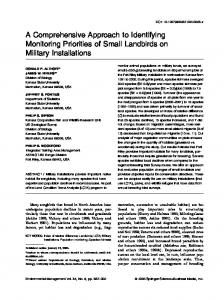
The Autonomous Reasoning Engine We have integrated the framework described in previous sections within a generic three layers hybrid autonomy architecture, the Autonomous Reasoning Engine (ARE), developed in response to an invitation to tender of the European Space Agency aiming at developing an integrated uniform approach for model based on board autonomy (OMC-ARE 2008). The spacecraft will be equipped with an ARE. The ARE interacts with the spacecraft and with the Ground Control Station to provide autonomous reasoning capabilities. From the spacecraft, it will receive information from the sensors, and delivers control commands to the actuators. With the Ground Control it will exchange information on the mission goals and initial mission plan, and it will also receive direct commands to activate ARE functionalities and to inspect the status of the ARE. From the logical point of view, the ARE is structured according to a generic three layers hybrid autonomy architecture: Deliberative layer, Executive layer, and Control layer (See Figure 2). The Deliberative Layer is responsible for generating mission plans, for validating the generated plans to ensure that they are guaranteed to achieve the mission goal from the current status of the controlled system, and for triggering re-planning whenever needed. This layer includes also an FDIR block which is activated in response to an anomaly (e.g., a fault or an assumption violation) detected by the Deliberative layer itself or by a lower layer to identify and then recover from the anomaly. Several recovery strategies can be embedded in the FDIR block depending on the degree of autonomy that we would like to achieve, on the complexity of the controlled spacecraft, and on the criticality of the identified problem. If the anomaly is due to a change in the environment or in the expected use of resources, then new assumptions can be computed, and the rest of the plan can
Mission Plan (MP)
Mission Goal (MG)
Plan Generation
Ground Commands
Plan Validation
FDIR
Deliberative
M Plan Execution and Monitoring High Level Sensing Information Executive
Low Level Sensing Routines
High Level Commands to Actuators
Low Level Actuation Routines
Control Low Level Sensing Information
Commands to Actuators
Figure 2: The ARE architecture. be validated w.r.t. the new assumptions. If the validation succeeds then its execution can be continued. Otherwise, a re-planning with the new assumptions can be triggered. If no recovery is possible, then a safe operational mode is entered waiting from intervention from Ground. The Executive layer is responsible for executing a given mission plan coming from Ground or generated by the upper layer. Moreover, it also carry out plan monitoring and, in case an anomaly (e.g., an assumption that is no longer satisfied, or an anomalous resource consumption) is detected it is responsible to give the control back to the FDIR block in the Deliberative layer. This layer executes a contingent plan according to the algorithm 1. The Executive layer collects diagnostic information (performed observations, executed commands, assumption violations) in order to provide them to the FDIR block in the Deliberative layer, whenever requested, to identify the possible cause of the anomaly (using algorithm 2) and activate the proper recovery function. The Control layer implements the conversion between the model-based level and the lower level of the spacecraft. It contains the low-level code that is responsible for the acquisition of sensing information and for sending low level commands to the actuators, and for estimating the resource consumption resulting from the execution of a command to be sent to upper layers. The control layer is implemented as a set of software procedures that are tailored to the control and monitoring of specific physical devices. The ARE functionalities are triggered according to a predefined Finite State Machine (FSM) that activates the different building block functionalities provided by the ARE to achieve the desired degree of autonomy. This FSM is responsible for responding to possible triggers coming from Ground or triggers coming from lower layers (e.g. because of a problem detected during plan execution) to activate FDIR functionalities, to re-plan or re-validate the remaining plan. A prototype of the ARE has been implemented on top of the N U SMV symbolic model checker (Cimatti et al. 2000) exploiting the Planning as Model Checking framework de-
veloped in (Cimatti et al. 1997; 2003; Cimatti, Roveri, and Bertoli 2004; Bertoli et al. 2006). N U SMV provides all the low level routines for the symbolic manipulation of the discrete model of the controlled system, and for implementing all the building blocks necessary for the implementation of the high level autonomy functionalities provided by the ARE (i.e. plan generation, plan validation, plan execution and monitoring, and for faults isolation). Within the prototype additional code has been developed to implement auxiliary functionalities typical of a spacecraft application, i.e. functionalities to upload a new model of the spacecraft to be used by the autonomy functionalities of the ARE, new assumptions, or new mission goals. Moreover, we have also implemented the low level routines responsible for the decoding of low level commands to be sent to the actuators, and low level functions to read the sensors and to build the internal representation to be used for the deliberative and executive activities provided by the ARE. We remark that the ARE is largely independent of the controlled system: the upper layers are application independent, bound to the application domain through the system model description; the dependencies related to the low-level platform interactions are localized in the Control layer that can be customized through dedicated APIs. Moreover, the whole ARE software is built on top of the POSIX C interface. Thus, the software can be deployed on any operating system providing a POSIX C interface (e.g. under RTEMS, Linux, Solaris, Windows).
Experimental Evaluation We experimented the proposed approach on two case studies, a planetary rover, and an orbiter. Both case studies are extracted from real-world domains, and we have interfaced the ARE with a spacecraft simulator. The spacecraft simulator is based on a library that contains the basic common functionalities (TC management, TM management, software bus services). The services offered by this library allow to easily integrate software components into a software bus. The spacecraft simulator can be run on a Linux PC host equipped with an hardware simulator (currently SiS (SIS ) for ERC32 and TSIM (TSIM2 ) for LEON3) or on a real target (FPGA board or ASIC board). Commanding (TC, scripts) as well as display and reporting (TM, reports, checks) are network transparent and support multiple users on the same simulation. We considered two different configurations for the planetary rover parametrized on the number of sub-components each dedicated to a different space experiment. The first configuration is composed of 3 sub-components responding to a total of 19 commands. The second configuration is composed of 17 sub-components responding to a total of 92 different commands. The orbiter case study is simpler and is composed of only 3 sub-components responding to a total of 9 different commands. The formal model of each of the three considered case studies has been specified in the N U SMV language starting from description of the spacecrafts in Matlab/Stateflow/Simulink. Similarly, the resource estimation functions have been implemented exploiting the information
Software Component
Rover
Operational Level
Software Component
Spacecraft SImulator API
Functional Level
Software Component
Software Bus Services (TM, TC, time, ...)
Operating System and Hardware Dependendent Software
Orbiter
Small
Full
ERC32
LEON3
ERC32
LEON3
ERC32
Initialization
33
13
282
113
9
LEON3
1
Plan Loading
3
1
6
2
2
0.5
Plan Validation
15
6.5
55
23
1
1
Plan Execution
116
121
125
121
16
16
Plan Generation
87
34
1349
540
6
2
time expressed in seconds
Figure 5: Performance characterization.
Hardware
Figure 3: The spacecraft simulator API. in the Matlab/Stateflow/Simulink models. The N U SMV models have been thoroughly validated against simulations generated from the Matlab/Stateflow/Simulink models, and against several properties written to be sure the N U SMV model (and the Matlab/Stateflow/Simulink from which the N U SMV model has been generated from) really captures expected behaviors of the corresponding spacecrafts. Rover
Orbiter
Small
Full
# State vars
40
116
16
# Action vars
2
2
2
# Observations
20
74
5
# Bool vars
423
147
77
State Space
267
2202
231
Reachable State Space
264
2194
223
Reach. BDD size
103
333
106
Diameter
31
61
33
Figure 4: Functional characterization. Figure 4 reports some information we gathered on the considered case studies while validating the specified respective formalizations. We report the number of state variables needed to specify the model, the number of variables needed to specify the actions, the number of observations we considered, the number of Boolean variables needed to perform a logarithmic encoding of the ranges of all the variables, the size of the search space and the size of the reachable state space from a given initial configuration. We report also the size of the BDD representing the set of reachable states, and the number of images needed to compute the set of reachable states from the initial configuration. In Figure 5 it is reported the time to perform the initialization of the reasoning engine w.r.t. the considered case study, the time required to build the internal representation of a mission plan generated on ground and sent on-board, the time to validate the loaded plan, the time to execute the validated plan, and finally the time required to build a new plan to achieve the goal. The times have been obtained running the ARE software on the two standard target hardware platforms considered.
For each of the case studies, we have identified realistic objectives, and instructed the simulator to present both nominal and anomalous conditions for planning and re-planning. Several simulations have been performed in order to evaluate the suitability of the approach w.r.t. different metrics. For instance, the rover mission characteristics as unpredictable local conditions on the planetary surface and with time-variable conditions; the rover mission constraints as limited bandwidth, intermittent visibility, long round trip delay; rover system operations to perform a measurement cycle that included movement, sample acquisition and sample preparation and distribution; the orbiter mission characteristics; the orbiter mission constraints; the orbiter system operations; and finally the development methodology. The approach has been experimented on two different simulation scenarios: (i) re-planning after fault; (ii) re-planning after an unexpected change in environment. The system has been run in order to characterize the approach on the following parameters: reliability (requirements coverage, generated plan compliance with the goal); availability (reaction time); and performance (processing power and memory required). The system has been characterized both from the functional point of view, and from the performance point of view. A typical scenario used to evaluate the system in terms of performance includes: initialization of models, loading of plan, plan validation, plan execution, anomaly detection and analysis, recovery, and finally plan execution. Figure 6 reports an excerpt of the characterization we carried out on the typical scenario for an observation window of 700 seconds using the primitives provided by RTEMS 4.9 (RTEMS ) running on the SiS hardware simulator for ERC32. Four threads are running on the platform: the Idle thread, the Main threads that implements the ARE FSM, the Child thread that is responsible of the different ARE functionalities, and the Monitor thread that contains the code to extract performance figures. The first plot on the left reports the percentage of CPU usage for the considered observation window. The plot in the middle reports the maximum stack used over time by the different threads. Finally, the plot on the right reports the memory used by the ARE in the given period. The vertical bars marks the beginning and end of the different steps. From left to right we have: initialization, loading of the plan, validation of the plan, execution of the plan, and waiting for new commands to arrive. The plots show that the CPU intensive steps are the initialization of the model, the loading of the plan and its validation. Once
100
200
300
400 time (sec)
500
700
d En
En
d
on
Ex ec
D
lid
n Pla
n
Va
In Loit E ad n Pdla
Pla
Pla L o n ad Va P lid lan ati B on eg Be in gin Pla n Ex ec Be gin
10000
In
it
Be
gin
stack usage (Kb) 15000 20000 25000
n
d En Ex ec n Pla
0
10000 600
Memory Used
5000
En
0 0
ati
on
En
e
on
on D
ati
n
lid
Ex ec
Be
gin
Pla
n
Va
In Loit E ad n Pdla d
Child TopLevel Monitor Idle
c Ex e n Pla
n
d ali Pla da n tio Be n gin Be gin
Pla L o n a V
En d
e
n
on
tio
D n
da Va li n Pla
Pla
in
Be g
stack usage (bytes) 20000Init 30000
Pla L o n ad Va P lid lan ati B on eg Be in gin Pla n Ex ec Be gin In Loit E ad n Pdla
0.01 0.001
e
d
40000
30000
100 gin
Be
cpu usage percentage In 0.1 1 10 it
Child TopLevel Monitor Idle
MEMORY USAGE
35000
STACK USAGE
50000
CPU % USAGE
0
100
200
300
400 time (sec)
500
600
700
0
100
200
300
400 time (sec)
500
600
700
Figure 6: The ARE characterization on SiS for ERC32 for the Planetary Rover. the execution of the plan starts, the child thread decreases its use of CPU since during the execution of a low level command it waits for the command to terminate before going on with the execution of the remaining part of the plan. At the same time the Idle thread increases its percentage use. Even though not reported in the plot, we remark that, an increase of CPU usage of the Child thread and a decrease of Idle CPU usage will be showed while performing plan generation. The Main thread, instead, is using a very low percentage of CPU (about 1.5%). The Monitor on the other hand uses a practically constant amount of CPU which is about 0.05%. The plots also show that the memory used by ARE grows during the initialization and also during the plan loading and validation. During plan execution it is almost constant, and it remains constant after the execution of the plan terminates. The reason for this behavior resides in the N U SMV internals used to represent the model (Cimatti et al. 2000). The ARE software and related material can be downloaded from http://es.fbk.eu/projects/esa omc-are upon request to the authors.
Related work The first notable approach to model-based autonomy is the Deep Space One (DS1) experiment (1998-2001) by the NASA agency. The DS1 was equipped with a “Remote Agent”(RA) (RA ) module that provided model-based executive capable of goal-driven planning and scheduling, diagnosis and recovery from injected faults. The model-based executive of the RA is the Livingstone model (Williams and Nayak 1996). Titan (Fesq et al. 2002) (developed by MIT) is the descendant of the Livingstone model. This executive is composed of two main function: a mode estimation and a mode reconfiguration. Mode estimation is responsible for updating the current state by taking into account the commands that have been issued, and the observations perceived from the controlled system. This is performed by taking into account the most likely possible state that is compatible with the history of executed actions, with gathered observations, and with the model of the system. Mode reconfiguration is responsible for updating the current status, making sure that the specified actions are still applicable and valid. The RA is similar in spirit to the one proposed in this work. Our approach differentiates from the RA since the same formal model is used in all the phases from the deliberative to the
executive levels. MUROCO-II (Kapellos 2005) is a support tool for a generic formal framework for the specification and verification of space missions. It implements a three layers framework, but the whole approach is off-line. Basically, actions and tasks of a mission can be specified and validated. The framework relies on the Esterel language, and simple temporal properties can be simulated, and formally proved. Our approach extends MUROCO-II in two main directions. First, MUROCO-II is a framework for an off-line activity taking place on ground, while the current approach focuses on technologies and tools for on-board autonomy. Second, the system developed in MUROCO is unable to deal with diagnosis, since the tools in Esterel focus on verification; planning is also out of reach for all those cases where nondeterminism has to be taken into account (with the environment interpreted in an adversarial manner); in our approach, both diagnosis and planning are covered. The MMOPS (Woods et al. 2006) approach develops an on-board system, TVCR (Timeline Verification, Control and Repair), that takes into account scheduling issues, and is able to carry out limited amounts of re-planning. The objective is to try and detect whether the mission time line currently being executed is still likely to achieve its goals and not to cause trouble given that the current conditions may have departed from the estimated ones, and in case of detected problem suggests possible repairs of the mission time line. The main components are a plan validator, an execution monitor, and a plan repair generator. The form of planning is very specific, and does not address the problem of defining a generic automated reasoning system to be reused in different settings and for different functionalities. Our approach implements functionalities similar to the ones of MMOPS, but in a unique formal framework within a three layers hybrid autonomous architecture.
Conclusions and future work We presented a unified model based approach to on-board autonomy. This approach relies on a symbolic representation of the system to control. The autonomy functionalities (plan generation, validation, execution, monitoring and FDIR) are all seen as symbolic transformations of the formal representation of the system to control. This approach allows for application of model checking techniques to val-
idate the symbolic representation of the system to control and to check for diagnosability conditions. Moreover, the underlying techniques can be used to realize the autonomy functionalities. We have implemented the approach in a prototype of an Autonomous Reasoning Engine relying on the N U SMV symbolic model checker. We have carried out a characterization of the approach using two case studies inspired by real on-going projects to understand it usability in the context of current space applications and available onboard computers. The obtained results were promising. There are several directions for improvements at different levels. The reasoning engine currently uses BDDs, it would be worth experimenting with SAT and also with SMT techniques to consider then in a unique framework both the continuous and the discrete components. As far as goals are considered, it would be worth extending the approach to deal with sequential goals. In parallel the approach could benefit from using more complex assumptions.
Acknowledgments This work was sponsored by the European Space Agency under ESA/ESTEC ITT AO/1-5184/06/NL/JD - ON BOARD MODEL CHECKING.
References Albore, A., and Bertoli, P. 2004. Generating Safe AssumptionBased Plans for Partially Observable Nondeterministic Domains. In AAAI, 495–500. AAAI Press / The MIT Press. Albore, A., and Bertoli, P. 2006. Safe LTL Assumption-Based Planning. In ICAPS, 193–202. AAAI. Bertoli, P.; Cimatti, A.; Roveri, M.; and Traverso, P. 2006. Strong planning under partial observability. Artif. Intell. 170(4-5):337– 384. Biere, A.; Cimatti, A.; Clarke, E. M.; Strichman, O.; and Zhu, Y. 2003. Bounded model checking. Advances in Computers 58:118–149. Bonet, B., and Geffner, H. 2000. Planning with Incomplete Information as Heuristic Search in Belief Space. In 5th ICAPS, 52–61. AAAI-Press. Bozzano, M.; Cimatti, A.; and Roveri, M. 2007. OMC-ARE — Technical Note (TN1). Technical Report OBMC-TN-FBK-01, Fondazione Bruno Kessler. Bryant, R. E. 1992. Symbolic Boolean manipulation with ordered binary-decision diagrams. ACM Comp. Surveys 24(3):293–318. Cavada, R.; Cimatti, A.; Franz´en, A.; Kalyanasundaram, K.; Roveri, M.; and Shyamasundar, R. K. 2007. Computing predicate abstractions by integrating BDDs and SMT solvers. In FMCAD, 69–76. IEEE. Cimatti, A., and Roveri, M. 2000. Conformant planning via symbolic model checking. J. Artif. Intell. Res. (JAIR) 13:305–338. Cimatti, A.; Giunchiglia, E.; Giunchiglia, F.; and Traverso, P. 1997. Planning via Model Checking: A Decision Procedure for AR. In Proceeding of ECP-97, volume 1348 of LNAI, 130–142. Toulouse, Fr: Springer. Cimatti, A.; Clarke, E. M.; Giunchiglia, F.; and Roveri, M. 2000. NuSMV: A New Symbolic Model Checker. STTT 2(4):410–425. Cimatti, A.; Pistore, M.; Roveri, M.; and Traverso, P. 2003. Weak, strong, and strong cyclic planning via symbolic model checking. Artif. Intell. 147(1-2):35–84.
Cimatti, A.; Pecheur, C.; and Cavada, R. 2003. Formal verification of diagnosability via symbolic model checking. In Gottlob, G., and Walsh, T., eds., IJCAI, 363–369. Morgan Kaufmann. Cimatti, A.; Roveri, M.; and Bertoli, P. 2004. Conformant planning via symbolic model checking and heuristic search. Artif. Intell. 159(1-2):127–206. Clarke, E. M.; Grumberg, O.; Jha, S.; Lu, Y.; and Veith, H. 2000. Counterexample-Guided Abstraction Refinement. In CAV, 154– 169. Clarke, E. M.; Grumberg, O.; and Peled, D. A. 1999. Model Checking. The MIT Press. ISBN 0-262-03270-7. Emerson, E. A. 1990. Temporal and modal logic. In Handbook of Theoretical Computer Science, Volume B: Formal Models and Sematics (B). 995–1072. Fesq, L.; Ingham, M.; Pekala, M.; Eepoel, J. V.; Watson, D.; and Williams, B. C. 2002. Model-based autonomy for the next generation of robotic spacecraft. http://groups.csail. mit.edu/mers/papers/IAC02 MIT paper.pdf. Ghallab, M.; Nau, D.; and Traverso, P. 2005. Automated Planning: Theory and Practice. Morgan Kaufman. Hopcroft, J., and Ullman, J. 1979. Introduction to Automata Theory, Languages and Computation. Addison-Wesley. Kapellos, K. 2005. Formal Robotic Mission Inspection and Debugging (MUROCO II) Executive Summary, Issue 1, ESA Contract 17987/03/NL/SFe. ftp://ftp.estec.esa.nl/pub/ wm/wme/obmc/MUROCO-TRA-EXSUM.pdf. Lahiri, S. K.; Nieuwenhuis, R.; and Oliveras, A. 2006. SMT techniques for fast predicate abstraction. In CAV 2006, LNCS, 424–437. Springer. McMillan, K. 1993. Symbolic Model Checking. Kluwer Academic Publ. Mikaelian, T.; Williams, B. C.; and Sachenbacher, M. 2005. Model-based monitoring and diagnosis of systems with softwareextended behavior. In AAAI, 327–333. AAAI Press. 2008. OMC-ARE: On Board Model Checking - Autonomous Reasoning Engine. http://es.fbk.eu/projects/esa omc-are/. Pnueli, A. 1977. The temporal logic of programs. In Proceedings of 18th IEEE Symp. on Foundation of Computer Science, 46–57. 2005. IEEE Standard for Property Specification Language (PSL). IEEE Std 1850-2005. Remote Agent. http://ic.arc.nasa.gov/projects/ remote-agent/. RTEMS — Real-Time Operating System for Multiprocessor Systems. http://www.rtems.com. S. Graf, and H. Saidi. 1997. Construction of Abstract State Graphs with PVS. In CAV’97, volume 1254 of LNCS, 72–83. Springer. SPARC instruction simulator (SIS). http://www. esa.int/TEC/Software engineering and standardisation/TECS2BUXBQE 0.html. TSIM2 LEON3. http://www.gaisler.com. Williams, B. C., and Nayak, P. P. 1996. A model-based approach to reactive self-configuring systems. In AAAI/IAAI, Vol. 2, 971– 978. Woods, M.; Long, D.; Aylett, R.; Baldwin, L.; and Wilson, G. 2006. Mars Mission On-Board Planner and Scheduler (MMOPS) Summary Report, Issue 1, ESA Contract 17987/03/NL/SFe CCN1. ftp://ftp.estec.esa. nl/pub/wm/wme/obmc/MMOPS-SUMRPT.pdf.


![A Comprehensive Approach to Transition - AUCD [PDF]](https://m.moam.info/img/260x300/a-comprehensive-approach-to-transition-aucd-pdf_647996a8098a9e3d658b45aa.jpg)
